RU2055373C1 - Layer of explosive linear charges - Google Patents
Layer of explosive linear charges Download PDFInfo
- Publication number
- RU2055373C1 RU2055373C1 SU4810682A RU2055373C1 RU 2055373 C1 RU2055373 C1 RU 2055373C1 SU 4810682 A SU4810682 A SU 4810682A RU 2055373 C1 RU2055373 C1 RU 2055373C1
- Authority
- RU
- Russia
- Prior art keywords
- blades
- charges
- linear
- soil
- stacker
- Prior art date
Links
- 239000002360 explosive Substances 0.000 title claims description 8
- 238000000034 method Methods 0.000 claims description 3
- 230000005284 excitation Effects 0.000 claims description 2
- 239000002689 soil Substances 0.000 abstract description 16
- 238000002360 preparation method Methods 0.000 abstract description 3
- 239000000126 substance Substances 0.000 abstract 1
- 230000015572 biosynthetic process Effects 0.000 description 3
- 229910000831 Steel Inorganic materials 0.000 description 2
- 239000011435 rock Substances 0.000 description 2
- 239000010959 steel Substances 0.000 description 2
- 229910001369 Brass Inorganic materials 0.000 description 1
- OKTJSMMVPCPJKN-UHFFFAOYSA-N Carbon Chemical compound [C] OKTJSMMVPCPJKN-UHFFFAOYSA-N 0.000 description 1
- 229910000975 Carbon steel Inorganic materials 0.000 description 1
- RYGMFSIKBFXOCR-UHFFFAOYSA-N Copper Chemical compound [Cu] RYGMFSIKBFXOCR-UHFFFAOYSA-N 0.000 description 1
- 229910000737 Duralumin Inorganic materials 0.000 description 1
- 239000010951 brass Substances 0.000 description 1
- 229910052799 carbon Inorganic materials 0.000 description 1
- 239000010962 carbon steel Substances 0.000 description 1
- 239000010949 copper Substances 0.000 description 1
- 229910052802 copper Inorganic materials 0.000 description 1
- 230000006378 damage Effects 0.000 description 1
- 238000005474 detonation Methods 0.000 description 1
- 238000010586 diagram Methods 0.000 description 1
- 238000010892 electric spark Methods 0.000 description 1
- 230000007717 exclusion Effects 0.000 description 1
- 238000007654 immersion Methods 0.000 description 1
- 230000009347 mechanical transmission Effects 0.000 description 1
- 238000007789 sealing Methods 0.000 description 1
- 239000002344 surface layer Substances 0.000 description 1
- 239000000725 suspension Substances 0.000 description 1
Images
Landscapes
- Soil Working Implements (AREA)
Abstract
Description
Изобретение относится к устройствам для автоматизированного погружения линейных зарядов взрывчатого вещества (ВВ), в основном детонирующего шнура, в приповерхностный слой грунта и может быть применено в сейсморазведке для механизированной подготовки взрывных источников сейсмических волн. Кроме того устройство может быть использовано для укладки телефонных и энергетических кабелей, а также шнуроподобных гибких предметов. The invention relates to devices for the automated immersion of linear charges of explosives (BB), mainly a detonating cord, in the surface layer of soil and can be used in seismic exploration for the mechanized preparation of explosive sources of seismic waves. In addition, the device can be used for laying telephone and power cables, as well as cord-like flexible items.
Известен погружатель детонирующего шнура, содержащий вертикальные укладывающие ножи, выпускные трубы с воронками для подачи линейных зарядов, при этом вертикальные укладывающие ножи оснащены дополнительными, вертикальными подрезающими ножами, установленными позади укладывающих с наружной стороны и фиксированных с помощью горизонтальных закрылков, при этом выпускные трубы-шнуропроводы с воронками размещены на дополнительных подрезающих ножах с возможностью передвижения по высоте подрезающих ножей и закрепления их хомутами [1]
Недостаток устройства заключается в плохой укупорке линейных зарядов внутри разрушенного грунта, в результате чего происходят сильные выбросы породы вместе с продуктами детонации заряда. Это существенно снижает отношение полезный сигнал-помеха.Known detonator detonating cord containing vertical laying knives, exhaust pipes with funnels for supplying linear charges, while vertical laying knives are equipped with additional, vertical cutting knives installed behind laying on the outside and fixed with horizontal flaps, while the exhaust pipes are cord with funnels placed on additional cutting knives with the possibility of movement along the height of the cutting knives and securing them with clamps [1]
The disadvantage of this device is the poor closure of linear charges inside the destroyed soil, as a result of which strong outbursts of rock occur along with the products of charge detonation. This significantly reduces the useful signal-to-noise ratio.
Наиболее близким к предлагаемому является укладчик линейных зарядов (погружатель детониpующего шнура), содержащий раму с закрепленным на ней блоком линейных зарядов, рабочие органы в виде вертикальных укладывающих ножей, выпускные трубы с воронками для подачи линейных зарядов, горизонтальные закpылки, оснащенный горизонтальными подрезающими пластинками со съемными трубчатыми наконечниками, размещенными в пазах задних граней пластин, и наклонными уплотняющими закрылками [2]
Недостаток данного устройства в том, что оно обеспечивает укупорку зарядов ВВ только в слабосвязанных и сыпучих грунтах. Большинство грунтов, слагающих верхнюю часть разреза, обладают достаточной крепостью, что приводит к образованию разорванной и растресканной породы при внедрении в нее укладывающих ножей любой конструкции.Closest to the proposed one is a linear charge stacker (detonating cord loader), containing a frame with a linear charge block fixed to it, working bodies in the form of vertical stacking knives, exhaust pipes with funnels for supplying linear charges, horizontal flaps equipped with horizontal cutting plates with removable tubular tips located in the grooves of the rear faces of the plates, and inclined sealing flaps [2]
The disadvantage of this device is that it provides capping explosive charges only in loosely coupled and loose soils. Most of the soils that make up the upper part of the section have sufficient strength, which leads to the formation of torn and cracked rocks when introducing laying knives of any design into it.
Целью изобретения является повышение эффективности возбуждения сейсмических волн путем улучшения укупорки зарядов ВВ. The aim of the invention is to increase the efficiency of excitation of seismic waves by improving the closure of explosive charges.
Цель достигается тем, что укладчик линейных зарядов ВВ, содержащий раму с закрепленным на ней блоком линейных зарядов, рабочие органы в виде вертикальных укладывающих ножей, выпускные трубы с воронками для подачи линейных зарядов и лопатки, дополнительно снабжен валом принудительного вращения, размещенным вертикально сзади рабочих органов, а эти лопатки выполнены эллиптическими и закреплены на валу принудительного вращения под углом 50о к его оси с углом атаки 45о и менее между малой осью симметрии эллиптической лопатки и направлением укладки линейных зарядов.The goal is achieved in that the BB stacker of linear charges, comprising a frame with a block of linear charges mounted on it, working bodies in the form of vertical stacking knives, exhaust pipes with funnels for supplying linear charges and blades, is additionally equipped with a forced rotation shaft located vertically behind the working bodies and these blades are made elliptical and secured to the shaft at an angle of forced rotation 50 about to its axis with an angle of attack of 45 ° or less between the minor axis of the elliptical vane and the direction of symmetry y masonry linear charges.
Предлагаемый укладчик линейных зарядов содержит новые, ранее не применявшиеся, элементы и связи между ними. Сюда относятся приводной вал с жестко закрепленными на нем эллипсовидными лопатками. Эти лопатки занимают определенное положение в пространстве, которое задается соответствующими углами наклона к оси вала (50о) и разворота лопаток вокруг большой оси эллипса (не более 45о). Это позволяет при вращении вала производить поочередное встряхивание комьев грунта, разрушенного рабочими оpганами. При этом частота встряхиваний определяется количеством лопаток и оборотами приводного вала и может быть легко подобрана для большого числа разновидностей почвы, включая и увлажненную. Встряхивание грунта приводит к его разрушению на более мелкие фракции и, следовательно, к лучшей укупорке линейного заряда. Кроме того выполнение засыпающего устройства в виде вертикально расположенного вала принудительного вращения позволяет разместить его на рабочих органах для образования траншей в разрабатываемой полости. Это приводит к тому, что в процессе укладки линейных зарядов в грунт отпадает необходимость предварительной подготовки поверхности земли.The proposed linear charge stacker contains new, previously unused, elements and the relationships between them. This includes the drive shaft with ellipsoid blades rigidly fixed to it. These vanes occupy a certain position in a space which is given by the respective angles of inclination to the shaft axis (50 o) and turn the blades around the major axis (maximum of 45). This allows you to rotate the shaft to alternately shake the clods of soil destroyed by working bodies. At the same time, the frequency of shaking is determined by the number of blades and revolutions of the drive shaft and can be easily selected for a large number of varieties of soil, including moist soil. Shaking the soil leads to its destruction into smaller fractions and, consequently, to a better capping of the linear charge. In addition, the implementation of the falling asleep device in the form of a vertically located shaft of forced rotation allows you to place it on the working bodies for the formation of trenches in the cavity being developed. This leads to the fact that in the process of laying linear charges in the soil there is no need for preliminary preparation of the earth's surface.
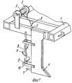
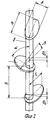
На фиг.1 представлена схема укладчика; на фиг.2 узел засыпающего устройства. Figure 1 presents a diagram of the stacker; in Fig.2 node falling asleep device.
Укладчик линейных зарядов может быть выполнен, например, следующим образом (фиг.1). На раму 1 в виде каpкаса из профилированной стали устанавливают блок катушек 2, выполненный в виде системы съемных легко вращающихся осей с разделяющимися щечками из дюралюминия, для предотвращения случаев образования искр от случайных ударов, с запасом линейных зарядов 3. К раме 1 на болтах (на фиг. 1 не показаны) присоединяются рабочие органы для образования траншей, выполненные в виде плоских ножей с заостренной передней кромкой из углеродистой стали. На задней грани ножа-рыхлителя 4 при помощи соответствующих хомутов крепятся трубы-шнуропроводы 5 из латунных, медных и других труб, не образующих электрических искр при ударах, на них закреплены воронка 6 и выпускная насадка 7. В этой же грани ножа-рыхлителя 4 при помощи хомутов 10 закрепляется вертикальный вал 8 в подшипниках 9 вращения с жестко посаженными на него эллиптическими лопатками 11. Эти лопатки 11 выполнены из углеродистой листовой стали в виде эллипсов с эксцентриситетом e 0,8 и величиной большой оси, на 20 мм превышающей половину толщины ножа-рыхлителя 4. При этом центральный угол между большими осями проекций этих лопаток на горизонтальную плоскость равен 120о, а расстояние между ними по оси вала 8 (Δ h) не менее 150 мм.The stacker of linear charges can be performed, for example, as follows (figure 1). On the
Принудительный привод во вращение вала 8 осуществляется посредством гидромоторов марки НШ-200, электромоторами или при помощи механической трансмиссии через разделительную муфту. Для этого на продольных брусьях рамы 1 размещается монтажная площадка, содержащая соответствующие отверстия для источника момента вращения и валов вращения и присоединения. The forced drive into the rotation of the
Укладчик линейных зарядов работает следующим образом. Stacker linear charges works as follows.
Транспортное средство вместе с присоединенным к нему укладчиком выдвигается в исходную точку профиля. Взрывная бригада производит установку блока катушек 2 с запасом линейных зарядов 3 на раму 1. Концы линейных зарядов 3 с катушек 2 вводят в приемные воронки 6 труб-шнуропроводов 5 и проталкивают их до выхода из выпускных насадок 7, после чего они закрепляются на поверхности земли и подается сигнал на движение транспортного средства. Перемещение транспортного средства вдоль профиля производится одновременно с опусканием рамы 1 на гидравлическом подвесе, внедрением ножей-рыхлителей 4 в грунт и вращением вертикального вала 8 в подшипниках 9 с жестко закрепленными эллиптическими лопатками 11. При этом ножи-рыхлители 4 вспарывают грунт и раскалывают его на достаточно крупные фракции, которые не обеспечивают надежной укупорки линейных зарядов 3, сматывающихся с катушек 2. Вал 8, вращаясь в подшипниках 9, присоединенных через хомуты 10 к ножам-рыхлителями 4, приводит к встряхиванию объема грунта, заключенного между эллиптическим лопатками 11, и его размельчению на более мелкие фракции. Размельченный грунт проваливается между лопатками 11 по валу 8 вниз и засыпает линейные заряды 3, выходящие из выпускных насадок 7 труб-шнуропроводов 5. При этом укупорка значительно улучшается. Транспортное средство продолжает движение по профилю, заряды 3, плотно зажатые в траншее мелкодисперсным грунтом, легко сматываются с катушек 2 и через воронки 6, трубы-шнуропроводы 5, выпускные насадки 7 ровными нитями укладываются на заданную глубину в грунт. The vehicle, together with the stacker attached to it, extends to the starting point of the profile. The explosive team installs a block of
По окончании процесса укладчик извлекается из грунта при помощи гидравлических цилиндров. Вращение вала 8, а вместе с ним и эллиптических лопаток 11, прекращается. Транспортное средство перемещается на новый пункт укладки линейных зарядов, по достижении которого операции повторяются. At the end of the process, the stacker is removed from the ground using hydraulic cylinders. The rotation of the
Экспериментальные исследования предлагаемого устройства, выполненные на его макете в составе шиpоко применяемых погружателей детонирующего шнура, показали, что по сравнению с укладчиком аналогичного назначения (прототип) предлагаемое устройство обеспечивает практически полную укупорку укладываемого линейного заряда, что в 1,5 раза повышает отношение полезный сигнал-помеха; увеличение производительности труда при автоматизированной укладке линейных зарядов благодаря исключению дополнительных операций подготовки и выравнивания поверхности, расчистки и выкорчевывания корней растительности. Experimental studies of the proposed device, performed on its layout as part of the widely used detonating cord loaders, showed that, compared with a similar purpose stacker (prototype), the proposed device provides almost complete closure of the stacked linear charge, which increases the useful signal ratio by 1.5 times interference; increase in labor productivity with automated laying of linear charges due to the exclusion of additional operations of preparing and leveling the surface, clearing and uprooting of the roots of vegetation.
Claims (1)
Priority Applications (1)
| Application Number | Priority Date | Filing Date | Title |
|---|---|---|---|
| SU4810682 RU2055373C1 (en) | 1990-04-05 | 1990-04-05 | Layer of explosive linear charges |
Applications Claiming Priority (1)
| Application Number | Priority Date | Filing Date | Title |
|---|---|---|---|
| SU4810682 RU2055373C1 (en) | 1990-04-05 | 1990-04-05 | Layer of explosive linear charges |
Publications (1)
| Publication Number | Publication Date |
|---|---|
| RU2055373C1 true RU2055373C1 (en) | 1996-02-27 |
Family
ID=21506363
Family Applications (1)
| Application Number | Title | Priority Date | Filing Date |
|---|---|---|---|
| SU4810682 RU2055373C1 (en) | 1990-04-05 | 1990-04-05 | Layer of explosive linear charges |
Country Status (1)
| Country | Link |
|---|---|
| RU (1) | RU2055373C1 (en) |
-
1990
- 1990-04-05 RU SU4810682 patent/RU2055373C1/en active
Non-Patent Citations (2)
| Title |
|---|
| 1. Авторское свидетельство СССР N 809022, кл. G 01V 1/13, 1981. * |
| 2. Авторское свидетельство СССР N 483639, кл. G 01V 1/13, 1973. * |
Similar Documents
| Publication | Publication Date | Title |
|---|---|---|
| CN202442785U (en) | Seabed shield machine vibration monitoring device for pre-treatment construction in base rock blast | |
| CN111238324A (en) | Blasting structure and blasting method | |
| GB2132567A (en) | Vibration apparatus | |
| CN109596022A (en) | Boulder blast processing method before a kind of shield cutter | |
| CN221879385U (en) | Blasthole arrangement structure | |
| EP0507331A1 (en) | Method of making a huge elongated space of square or rectangular cross section under the ground | |
| RU2103509C1 (en) | Block working method | |
| JP2781845B2 (en) | Underground obstacle removal method in propulsion work | |
| JPH05247939A (en) | How to dismantle deep underground obstacles | |
| RU2097679C1 (en) | Method of driving of mine working | |
| SU1752947A1 (en) | Method of forming trenches by blasting | |
| RU2068170C1 (en) | Method of formation of trenches by blast | |
| SU1749863A1 (en) | Method of excitation of seismic waves | |
| SU714323A1 (en) | Device for exciting seismic signals | |
| RU2100826C1 (en) | Method of excitation of seismic waves | |
| SU1661422A1 (en) | Method for working inclined ore obstructions | |
| SU809022A1 (en) | Detonation cord sinker | |
| SU866099A1 (en) | Method of driving wells in earth | |
| SU717336A1 (en) | Mineral-processing method and apparatus | |
| SU1099006A1 (en) | Mechanized unit for constructing hydraulic and land-reclamation structures | |
| SU333259A1 (en) | A method of puffing up a solid medium by an explosion of a8-a-union-i.> & -.-.- ,, • .- ,, -. .-: "" Uji ^ a: lri (:. Jiifii - ^ i; iJ4in? F LIBRARY | |
| SU1594250A1 (en) | Underwater tube deeper | |
| SU1656130A1 (en) | Method of driving the under-vault part of large-span underground structure | |
| SU976071A1 (en) | Method of forming an undercutting space | |
| SU1105841A1 (en) | Linear explosive charge placer |