RU2065110C1 - End-face seal - Google Patents
End-face seal Download PDFInfo
- Publication number
- RU2065110C1 RU2065110C1 RU94027483A RU94027483A RU2065110C1 RU 2065110 C1 RU2065110 C1 RU 2065110C1 RU 94027483 A RU94027483 A RU 94027483A RU 94027483 A RU94027483 A RU 94027483A RU 2065110 C1 RU2065110 C1 RU 2065110C1
- Authority
- RU
- Russia
- Prior art keywords
- sealing
- sealing rings
- working edge
- rings
- ring
- Prior art date
Links
- 238000007789 sealing Methods 0.000 claims abstract description 40
- 230000000712 assembly Effects 0.000 abstract 1
- 238000000429 assembly Methods 0.000 abstract 1
- 230000000694 effects Effects 0.000 abstract 1
- 239000000126 substance Substances 0.000 abstract 1
- 239000002184 metal Substances 0.000 description 3
- 229910000851 Alloy steel Inorganic materials 0.000 description 1
- 239000010754 BS 2869 Class F Substances 0.000 description 1
- 229910000831 Steel Inorganic materials 0.000 description 1
- 229910045601 alloy Inorganic materials 0.000 description 1
- 239000000956 alloy Substances 0.000 description 1
- 238000000034 method Methods 0.000 description 1
- 230000002085 persistent effect Effects 0.000 description 1
- 239000002689 soil Substances 0.000 description 1
- 239000007787 solid Substances 0.000 description 1
- 239000010959 steel Substances 0.000 description 1
Images
Landscapes
- Mechanical Sealing (AREA)
- Sealing Devices (AREA)
Abstract
Description
Изобретение относится к уплотнительной технике, в частности, уплотнениям узлов ходовой системы гусеничного транспортного средства. The invention relates to a sealing technique, in particular, to seals of nodes of a running system of a tracked vehicle.
Известно торцовое уплотнение опорных катков гусеничной машины, содержащее взаимодействующие между собой неподвижное и вращающееся уплотнительные детали, одно из которых выполнено металлическим, другое упругим, причем упругий элемент выполнен армированным и его рабочая кромка взаимодействует с неподвижным кольцом. /а.с. СССР N 1733788, кл. F 16 j 15/34 от 1990 г./. A mechanical seal of the track rollers of a tracked vehicle is known, comprising stationary and rotating sealing parts interacting with each other, one of which is made of metal and the other is elastic, the elastic element being made reinforced and its working edge interacting with the stationary ring. / a.s USSR N 1733788, class F 16 j 15/34 from 1990 /.
Недостатком упомянутого уплотнения является недостаточная надежность диафрагмы, которая при эксплуатации гусеничной машины может повреждаться твердыми включениями грунта или изнашиваться абразивом. The disadvantage of this seal is the lack of reliability of the diaphragm, which during operation of the tracked vehicle can be damaged by solid inclusions of the soil or wear out with an abrasive.
Известно торцовое уплотнение опорных катков гусеничной машины, содержащее размещенные в корпусных деталях взаимодействующие между собой неподвижное и вращающееся уплотнительные кольца и размещенные между корпусными деталями и уплотнительными кольцами два эластичных кольца круглого сечения, причем поверхность корпусных деталей, обращенная в сторону уплотнительных колец выполнена в виде усеченного конуса с большим основанием со стороны контакта уплотнительных колец, поверхность уплотнительных колец, обращенная в сторону корпусной детали выполнена конусной, аналогичной поверхности корпусной детали и переходящей с одной стороны в торцовую, оканчивающуюся кольцевой части, перпендикулярной оси уплотнения, а с другой стороны снабженную упорным буртиком. На обращенных друг к другу взаимодействующих сторонах неподвижного и вращающегося уплотнительных колец выполнены рабочие кромки. /пат. CША N 3180648, кл. 277-92 от 24.07.65 г./
Недостатком упомянутого уплотнения является то, что оба уплотнительных кольца изготовляются из высоколегированных дефицитных и дорогих сталей или сплавов, работающие контактирующие поверхности должны обрабатываться с очень высокой точностью, что не всегда может быть обеспечено существующим уровнем производства.A mechanical seal of the track rollers of a tracked vehicle is known, comprising stationary and rotating sealing rings located in the body parts, and two elastic O-rings located between the body parts and the sealing rings, the surface of the body parts facing the sealing rings being made in the form of a truncated cone with a large base on the contact side of the sealing rings, the surface of the sealing rings facing the body the parts are made conical, similar to the surface of the body part and passing from one side to the end, ending with the annular part perpendicular to the axis of the seal, and on the other hand provided with a persistent shoulder. On the interacting sides of the stationary and rotating sealing rings facing each other, working edges are made. / pat. US N 3180648, CL 277-92 from 07.24.65 g. /
The disadvantage of this seal is that both o-rings are made of highly alloyed, scarce and expensive steels or alloys, the working contact surfaces must be machined with very high accuracy, which cannot always be ensured by the existing level of production.
Задачей изобретения является повышение надежности уплотнения при сокращении расхода высоколегированной стали. The objective of the invention is to increase the reliability of the seal while reducing the consumption of high alloy steel.
Задача решается тем, что вращающееся уплотнительное кольцо выполнено эластичным, армированным жестким каркасом, форма которого выполнена копирующей поверхность уплотнительного кольца, обращенную к корпусной детали, а кольцевая часть каркаса, перпендикулярная оси уплотнения расположена на уровне контакта уплотнительных колец, причем отношение расстояния "а" от рабочей кромки вращающегося уплотнительного кольца до кольцевой поверхности каркаса к высоте "б" рабочей кромки равно 2.2,5 и отношение высоты "б" рабочей кромки к ее толщине "в" равно 0,75.1,25. The problem is solved in that the rotating sealing ring is made of an elastic, reinforced rigid frame, the shape of which is made by copying the surface of the sealing ring facing the housing part, and the annular part of the frame perpendicular to the axis of the seal is located at the contact level of the sealing rings, and the ratio of the distance "a" from the working edge of the rotating sealing ring to the annular surface of the frame to the height "b" of the working edge is 2.2.5 and the ratio of the height "b" of the working edge to its thickness "in" ra but 0,75.1,25.
На чертеже изображено упомянутое торцовое уплотнение. The drawing shows the mentioned mechanical seal.
Уплотнение содержит неподвижное металлическое уплотнительное кольцо I и вращающееся уплотнительное кольцо 2, взаимодействующие между собой и размещенные в корпусных деталях 3 и 4. Между корпусными деталями 3 и 4 и уплотнительными кольцами 1 и 2 расположены эластичные кольца круглого сечения 5 и 6, служащие нажимными элементами для уплотнительных колец 1 и 2. Поверхности 7 и 8 корпусных деталей 3 и 4 выполнены в виде усеченного конуса с основанием со стороны контакта уплотнительных колец. Поверхности 9 и 10 уплотнительных колец 1 и 2, обращенные в сторону корпусных деталей 3 и 4, также выполнены конусными, аналогичными поверхностям 7 и 8 корпусных деталей 3 и 4. Поверхности 9 и 10 со стороны контакта уплотнительных колец переходят в кольцевые поверхности 11 и 12, перпендикулярные оси уплотнения, а с противоположной стороны снабжены буртиками 13 и 14, служащими для удерживания колец 5 и 6 на кольцах 1 и 2 от спадания с них в состоянии перед сборкой узла уплотнения. На неподвижном кольце 1 выполнена кольцевая рабочая поверхность 15, перпендикулярная оси уплотнения. Вращающееся уплотнительное кольцо 2 выполнено эластичным, например, из резины, армировано жестким каркасом 16. Рабочая кромка 17 уплотнительного кольца 2 выполнена в виде кольцевого выступа, она контактирует с плоской рабочей поверхностью 15 уплотнительного кольца 1. Каркас 16 расположен внутри уплотнительного кольца 2, его форма копирует поверхности 10 и 12, а кольцевая часть 18 каркаса, перпендикулярная оси уплотнения, расположена на уровне контакта уплотнительных колец, т.е. является жесткой опорой рабочей кромки 17. The seal contains a fixed metal sealing ring I and a rotating sealing ring 2, interacting with each other and placed in the housing parts 3 and 4. Between the housing parts 3 and 4 and the sealing rings 1 and 2 are elastic round rings 5 and 6, which serve as pressure elements for O-rings 1 and 2. The surfaces 7 and 8 of the housing parts 3 and 4 are made in the form of a truncated cone with a base on the contact side of the O-rings. The surfaces 9 and 10 of the sealing rings 1 and 2, facing the housing parts 3 and 4, are also made conical, similar to the surfaces 7 and 8 of the housing parts 3 and 4. The surfaces 9 and 10 from the contact side of the sealing rings pass into the annular surfaces 11 and 12 perpendicular to the axis of the seal, and on the opposite side are provided with shoulders 13 and 14, which serve to hold the rings 5 and 6 on the rings 1 and 2 from falling from them in the state before assembly of the seal assembly. On the stationary ring 1 is made an annular working surface 15, perpendicular to the axis of the seal. The rotating sealing ring 2 is made elastic, for example, from rubber, reinforced with a rigid frame 16. The working edge 17 of the sealing ring 2 is made in the form of an annular protrusion, it is in contact with the flat working surface 15 of the sealing ring 1. The frame 16 is located inside the sealing ring 2, its shape copies surfaces 10 and 12, and the annular part 18 of the frame, perpendicular to the axis of the seal, is located at the contact level of the sealing rings, i.e. is a rigid support of the working edge 17.
Для обеспечения надежности уплотнения, в котором применяется контакт плоской металлической поверхности с эластичной рабочей кромкой, важно выдержать оптимальное соотношение между расстоянием "а" от рабочей кромки до части 18 каркаса 16 к высоте "б" рабочей кромки 170 равное 2.2,5, что обеспечивает необходимые упругие свойства рабочей кромки. Кроме того, необходимо выдержать оптимальное отношение высоты "б" рабочей кромки 17 к ее толщине "в", равное 0,75.1,25, что обеспечивает требуемую жесткость и устойчивость рабочей кромки. To ensure the reliability of the seal, in which the contact of a flat metal surface with an elastic working edge is used, it is important to maintain the optimal ratio between the distance "a" from the working edge to the part 18 of the frame 16 to the height "b" of the working edge 170 of 2.2.5, which provides the necessary elastic properties of the working edge. In addition, it is necessary to maintain the optimal ratio of the height "b" of the working edge 17 to its thickness "c", equal to 0.75.1.25, which provides the required rigidity and stability of the working edge.
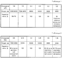
Экспериментальные исследования уплотнений по определению выше названных отношений приведены в табл. 1 и 2. Experimental studies of seals to determine the above relationships are given in table. 1 and 2.
Как видно из табл. 1 и 2 отношения а/б, равное 2.2,5, и б/в, равное 0,75.1,25 обеспечивает максимальный ресурс и 100%-ную герметичность. As can be seen from the table. 1 and 2 ratios a / b, equal to 2.2.5, and b / c, equal to 0.75.1.25 provides the maximum resource and 100% tightness.
Claims (1)
Priority Applications (1)
| Application Number | Priority Date | Filing Date | Title |
|---|---|---|---|
| RU94027483A RU2065110C1 (en) | 1994-07-20 | 1994-07-20 | End-face seal |
Applications Claiming Priority (1)
| Application Number | Priority Date | Filing Date | Title |
|---|---|---|---|
| RU94027483A RU2065110C1 (en) | 1994-07-20 | 1994-07-20 | End-face seal |
Publications (2)
| Publication Number | Publication Date |
|---|---|
| RU94027483A RU94027483A (en) | 1996-05-20 |
| RU2065110C1 true RU2065110C1 (en) | 1996-08-10 |
Family
ID=20158782
Family Applications (1)
| Application Number | Title | Priority Date | Filing Date |
|---|---|---|---|
| RU94027483A RU2065110C1 (en) | 1994-07-20 | 1994-07-20 | End-face seal |
Country Status (1)
| Country | Link |
|---|---|
| RU (1) | RU2065110C1 (en) |
Families Citing this family (1)
| Publication number | Priority date | Publication date | Assignee | Title |
|---|---|---|---|---|
| RU173972U1 (en) * | 2016-12-20 | 2017-09-22 | Общество с ограниченной ответственностью "Газпром трансгаз Казань" | DEVICE FOR SEALING SHELVES INTENDED FOR PASSING COMMUNICATIONS |
-
1994
- 1994-07-20 RU RU94027483A patent/RU2065110C1/en active
Non-Patent Citations (1)
| Title |
|---|
| 1. Авторское свидетельство СССР N 1733788, кл. F 16 J 15/34, 1990. 2. Патент США N 3180648, кл. 277-92, 1965. * |
Also Published As
| Publication number | Publication date |
|---|---|
| RU94027483A (en) | 1996-05-20 |
Similar Documents
| Publication | Publication Date | Title |
|---|---|---|
| CA1314063C (en) | End face seal assembly | |
| MX9704266A (en) | Seal for a universal joint trunnion. | |
| ES265297U (en) | "TRIPODE HOMOCINETIC BOARD". | |
| FR2686140B1 (en) | GASKET JOINT BETWEEN PIPES AND SEALING FOR SUCH A JOINT. | |
| CA2517407A1 (en) | Washpipe seal assembly | |
| US20190186632A1 (en) | Integrated debris barrier on metal face seals | |
| ES296370U (en) | Slip joint seal assembly | |
| GB1285272A (en) | Gland seal assemblies | |
| FR2354493A1 (en) | PERFECTED SEAL, ESPECIALLY FOR HINGE AXLES OF TRACK VEHICLE SKATES | |
| RU2065110C1 (en) | End-face seal | |
| US4981311A (en) | Coupling assembly | |
| US2480908A (en) | Seal | |
| US9822883B2 (en) | Load ring for seal assembly and seal assembly of machine | |
| IT8321680V0 (en) | OIL SEAL GASKET FOR ARTICULATED JOINTS OF LUBRICATED TYPE CHAINS, ESPECIALLY FOR TRACKED VEHICLES. | |
| ES8301343A1 (en) | A SEAT AND SEAL SET ADAPTED TO BE USED WITH A BALL VALVE ELEMENT. | |
| CN214661917U (en) | Magnetic sealing protector for waste gas fan | |
| US1927507A (en) | High pressure compressor packing | |
| JP3755656B2 (en) | Seal chain | |
| FR2358516A1 (en) | BUCKET CHAIN SEAL FOR DRAGGER | |
| JPH0543324Y2 (en) | ||
| FR2369469A1 (en) | PISTON RING ASSEMBLY | |
| SU1499034A1 (en) | Face seal | |
| EP0235182A1 (en) | Annular seal assembly | |
| US1882679A (en) | Seal | |
| CN218023795U (en) | Rolling element with good sealing performance |