RU2068356C1 - Multipurpose freight boxcar - Google Patents
Multipurpose freight boxcar Download PDFInfo
- Publication number
- RU2068356C1 RU2068356C1 SU5040378A RU2068356C1 RU 2068356 C1 RU2068356 C1 RU 2068356C1 SU 5040378 A SU5040378 A SU 5040378A RU 2068356 C1 RU2068356 C1 RU 2068356C1
- Authority
- RU
- Russia
- Prior art keywords
- flooring
- car
- movably
- tier
- supports
- Prior art date
Links
- 238000009408 flooring Methods 0.000 claims abstract description 16
- 239000007787 solid Substances 0.000 abstract description 4
- 239000000126 substance Substances 0.000 abstract 1
- 238000010586 diagram Methods 0.000 description 4
- 230000015572 biosynthetic process Effects 0.000 description 2
- 238000010276 construction Methods 0.000 description 1
Images
Landscapes
- Fittings On The Vehicle Exterior For Carrying Loads, And Devices For Holding Or Mounting Articles (AREA)
Abstract
Description
Изобретение относится к конструкциям транспортных средств для перевозке преимущественно легковых автомобилей и твердых грузов. The invention relates to the construction of vehicles for the transportation of mainly cars and solid loads.
Известен универсальный крытый грузовой вагон, содержащий ходовую часть с кузовом, продольные опоры, закрепленные посередине боковых стенок кузова, настил, устанавливаемый на указанные опоры для образования второго яруса и выполненный из плоских элементов прямоугольной формы. (Патент США N 4281870, кл. В 61 D 3/02, 1981). A universal covered freight wagon is known, comprising a chassis with a body, longitudinal supports fixed in the middle of the side walls of the body, a floor installed on said supports to form a second tier and made of flat rectangular elements. (U.S. Patent No. 4,281,870, class B 61 D 3/02, 1981).
Недостатками известного универсального крытого грузового вагона являются сложность конструкции и значительные затраты труда при образовании второго настила пола, располагаемого над основным. The disadvantages of the well-known universal covered freight car are the complexity of the design and significant labor costs in the formation of the second flooring, located above the main one.
Техническим результатом изобретения является упрощение конструкции крытого грузового вагона и уменьшение затрат труда при образовании второго настила пола, располагаемого над основным. The technical result of the invention is to simplify the design of a covered freight car and reduce labor costs during the formation of a second flooring located above the main one.
Технический результат достигается тем, что в универсальном крытом грузовом вагоне каждая торцовая стенка кузова выполнена в виде двух расположенных одна над другой для соответствующих ярусов двухстворчатых дверок, между которыми размещен опорный брус, при этом указанный настил разделен на две секции, каждая из которых одним концом подвижно соединена с соответствующим опорным брусом, а другим концом соединена с трособлочным механизмом перемещения секций настила, причем плоские элементы каждой секции настила взаимодействуют между собой подвижно. The technical result is achieved by the fact that in the universal covered freight car each end wall of the body is made in the form of two double-leaf doors located one above the other for the corresponding tiers, between which a support beam is placed, while the said flooring is divided into two sections, each of which is movably one end connected to the corresponding supporting beam, and the other end connected to a cable block mechanism for moving sections of the flooring, and the flat elements of each section of the flooring interact between themselves th mobile.
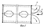
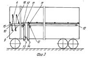
На фиг. 1 изображена схема вагона, вид с торца; на фиг.2 схема вагона, вид сверху; на фиг.3 кинематическая схема механизма перемещения трапов. In FIG. 1 shows a diagram of a car, end view; figure 2 diagram of the car, a top view; figure 3 kinematic diagram of the mechanism for moving the ladders.
Универсальный крытый грузовой вагон состоит из установленного на ходовые части 1 корпуса 2 с крышей 3 и специальными настилами 4, которыми он разделен на два яруса: нижний А и верхний В. На боковых (продольных) стенках 5 вагона закреплены опоры 6, на которых последовательно размещены два настила 4 (при перевозке автомобилей в два яруса). Каждая боковая стенка вагона имеет при этом также обычный подвижный центральный щит, который снабжен откидным упором по типу опоры 6 и на фиг. не показан. Поперечные (торцовые) стенки вагона выполнены в виде двух расположенных одна над другой двухстворчатых дверок 7, высота которых соответствует высоте ярусов А и Б. Между дверками с каждого торца вагона расположен опорный брус 8, который жестко взаимосвязан с боковыми стенками 5. Каждый из специальных настилов 4 выполнен в виде взаимосвязанных подвижно плоских элементов прямоугольной формы и подключен посредством трособлочной связи, которая включает трос 9 и блоки 10, 11, 12 к механизму перемещения в виде барабана 13 со съемными рукоятками 14. Блоки 10, 11, 12 закреплены на боковых стенках, а барабаны 13 под полом вагона. Через блоки 10, 11, 12 пропущен бесконечный трос 9, соответствующие концы которого закреплены на барабане 13. Кинематическая схема механизма перемещения настилов, представленная на фиг.3, является зеркальным отражением схемы на противоположной боковой стенке вагона (одновременно могут перемещать настилы 4, вращая барабаны 13 рукоятками 14 четыре и более человек). Каждый настил 4 своим начальным элементом 15 подвижно связан с соответствующим опорным брусом 8 и одновременно своим концевым элементом 16 подключен к своему тросу 9. A universal covered freight car consists of a body 2 installed on the chassis 1 with a roof 3 and
В процессе эксплуатации, например, для перевозки автомобиля двустворчатые дверки 7 раскрывают (показано стрелками) и они занимают положение, обозначенное пунктирными линиями как продолжение боковых (продольных) стенок 5 вагона. Специальные настилы 4 с помощью механизма перемещения устанавливают на опорах 6. При этом, вращая по стрелке за рукоятки 14 барабаны 13, механизмом перемещения посредством троса 9, взаимосвязанного с концевыми элементами 16, передвигают настилы 4 (его элементы начинают занимать вместо вертикального горизонтальное положение на опорах 6) навстречу друг другу, до их соприкосновения. Погрузка производится самоходом по стрелке В с соответствующего торца вагона (возможна и на оба яруса одновременно с двух сторон, что позволит значительно сократить время на операции). По окончании погрузки дверки закрывают. Разгрузка производится в обратной последовательности. При погрузке и перевозке твердых грузов вообще или при движении вагона в обратном направлении, в частности, чтобы исключить холостые пробеги при транспортировке автомобилей, настилы 4, складывая их по типу "гармошки", передвигают механизмом перемещения в обратном направлении, в результате каждый из них занимает вертикальное положение (показано на фиг.3) в соответствующем конце вагона примерно на длину 0,8 1,0 м. В освободившееся пространство (между сложенными трапами) загружают крупногабаритный груз через подвижный центральный щит, как у обычных железнодорожных вагонов. В случае погрузки мелкого штучного груза, например, в ящиках, бочках и т.д. трапы не убирают и погрузку также можно производить в двух ярусах, используя более полно объем вагона. По окончании погрузки закрывают двухстворчатые дверки и вагон используют по назначению. During operation, for example, for transporting a car, the double-
Таким образом, конструкция вагона предусматривает возможность перевозки как легковых автомобилей в двух ярусах в прямом направлении и тем самым использовать более полно его грузоподъемность, так и различных твердых грузов (включая крупногабаритные) в обратном направлении, исключая при этом холостые пробеги. Thus, the design of the car provides for the possibility of transporting both cars in two tiers in the forward direction and thereby use its full load capacity and various solid loads (including bulky) in the opposite direction, excluding idle runs.
Claims (1)
Priority Applications (1)
| Application Number | Priority Date | Filing Date | Title |
|---|---|---|---|
| SU5040378 RU2068356C1 (en) | 1992-04-29 | 1992-04-29 | Multipurpose freight boxcar |
Applications Claiming Priority (1)
| Application Number | Priority Date | Filing Date | Title |
|---|---|---|---|
| SU5040378 RU2068356C1 (en) | 1992-04-29 | 1992-04-29 | Multipurpose freight boxcar |
Publications (1)
| Publication Number | Publication Date |
|---|---|
| RU2068356C1 true RU2068356C1 (en) | 1996-10-27 |
Family
ID=21603329
Family Applications (1)
| Application Number | Title | Priority Date | Filing Date |
|---|---|---|---|
| SU5040378 RU2068356C1 (en) | 1992-04-29 | 1992-04-29 | Multipurpose freight boxcar |
Country Status (1)
| Country | Link |
|---|---|
| RU (1) | RU2068356C1 (en) |
-
1992
- 1992-04-29 RU SU5040378 patent/RU2068356C1/en active
Non-Patent Citations (1)
| Title |
|---|
| Патент США N 4281870, кл. B 61 D 3/02, 1981. * |
Similar Documents
| Publication | Publication Date | Title |
|---|---|---|
| US3738511A (en) | Convertible railway hopper car | |
| RU2393967C9 (en) | Transloading system and railroad car to be used therewith | |
| RU2374107C2 (en) | Method to transship cargoes and appropriate transportation system | |
| US3799479A (en) | Loading and unloading equipment for aircraft | |
| US2929339A (en) | Freight loading apparatus | |
| EA023761B1 (en) | Convertible trailer | |
| US4221427A (en) | Convertible trailer body construction | |
| US3892188A (en) | Auto transporting passenger train car | |
| RU2068356C1 (en) | Multipurpose freight boxcar | |
| US3504636A (en) | Railroad car construction | |
| RU2282548C2 (en) | Turnable for slewing carrying gear of flat car for combination rail and road carriages | |
| RU2445220C2 (en) | Rack car with support platforms moving between transporting position and position of motion between cars, and train consisting of said cars | |
| US2775355A (en) | Cargo carrier | |
| FI90844C (en) | Versatile utility car | |
| US3709181A (en) | Cargo vessels | |
| US2081178A (en) | Apparatus for unloading and loading railway vehicles | |
| US3752336A (en) | Vehicle loading and storage system for wheeled containers | |
| RU204313U1 (en) | WAGON-PLATFORM | |
| US1946013A (en) | Plural deck vehicle body | |
| RU2068357C1 (en) | Freight car | |
| US3096730A (en) | Center load container car | |
| RU174355U9 (en) | BOXCAR | |
| RU2347699C2 (en) | Flatcar to carry cars, piece and package cargoes | |
| RU40280U1 (en) | Covered Freight Wagon | |
| RU76302U1 (en) | UNIVERSAL Covered Wagon |