RU2068942C1 - Bridge plug - Google Patents
Bridge plug Download PDFInfo
- Publication number
- RU2068942C1 RU2068942C1 SU5055215A RU2068942C1 RU 2068942 C1 RU2068942 C1 RU 2068942C1 SU 5055215 A SU5055215 A SU 5055215A RU 2068942 C1 RU2068942 C1 RU 2068942C1
- Authority
- RU
- Russia
- Prior art keywords
- piston
- radial channel
- housing
- casing
- switching device
- Prior art date
Links
Images
Landscapes
- Pipe Accessories (AREA)
Abstract
Description
Изобретение относится к области нефтегазодобывающей промышленности, а именно к устройствам для разобщения пластов при консервации, эксплуатации и капитальном ремонте скважин. The invention relates to the field of oil and gas industry, and in particular to devices for separating layers during the conservation, operation and overhaul of wells.
Известно устройство, устанавливаемое в скважине на трубах, включающее корпус с радиальным каналом, обратный клапан, уплотнительный элемент, переводник с осевым и радиальным каналами и обратным клапаном, установленным в осевом канале и соединенный с переводником перепускной клапан с радиальными каналами и фиксирующим элементом (I). A device is known that is installed in a well in pipes, including a housing with a radial channel, a check valve, a sealing element, a sub with axial and radial channels and a check valve installed in the axial channel and connected to the sub bypass valve with radial channels and a fixing element (I) .
Недостаток устройства сложность конструкции и, как следствие этого, относительно невысокая эксплуатационная надежность. Кроме того, при использовании в конструкции устройства металлического уплотнительного элемента, например из разбуриваемых высокопластичных металлических пластов, для повышения эксплуатационной надежности устройства требуется иметь высокопрочные трубы, на которых устройство устанавливают в скважине, и мощный насосный агрегат для создания больших давлений пакеровки уплотнительного элемента. The disadvantage of this device is the complexity of the design and, as a consequence, the relatively low operational reliability. In addition, when using a metal sealing element in the device design, for example, from drilled highly plastic metal layers, to increase the operational reliability of the device, it is necessary to have high-strength pipes on which the device is installed in the well, and a powerful pump unit to create high packer packing pressures.
Известно также устройство, включающее корпус в виде стакана с радиальным каналом, обратный клапан, уплотнительный элемент, переводник с радиальным каналом, связанный с корпусом, и подвеску в виде труб (II). Данное устройство при использовании в конструкции металлического уплотнительного элемента для повышения эксплуатационной надежности, при разобщении пластов в скважине можно установить в обсадной колонне при избыточных давлениях запакеровки уплотнительного элемента не менее 40-50 МПа, что требует иметь в наличии высокопрочные трубы (насосно-компрессорные), на которых устройство устанавливается в скважине, и мощные насосные агрегаты для создания таких высоких избыточных давлений. A device is also known that includes a housing in the form of a cup with a radial channel, a check valve, a sealing element, a sub with a radial channel connected to the housing, and a suspension in the form of pipes (II). This device, when used in the design of a metal sealing element to increase operational reliability, when uncoupling the layers in the well, can be installed in the casing at excessive packing sealing pressure of at least 40-50 MPa, which requires the availability of high-strength pipes (tubing), on which the device is installed in the well, and powerful pumping units to create such high excess pressures.
Необходимый технический результат достигается тем, что мостовая пробка, включающая корпус в виде стакана с радиальным каналом, обратный клапан, уплотнительный элемент, переводник с радиальным каналом, связанный с корпусом, и подвеску в виде труб, снабжена ступенчатым поршнем, размещенным в переводнике, и ограничителем верхнего перемещения поршня, а переводник выполнен в виде ступенчатого патрубка под ступенчатый поршень, образующего с последним кольцевую полость, имеет дополнительный радиальный канал, сообщающий внешнее пространство с кольцевой полостью, и зафиксирован меньшей ступенью в корпусе, при этом ступенчатый поршень образует с корпусом и меньшей ступенью патрубка подпоршневую полость, которая заполнена пакерующей жидкостью. The necessary technical result is achieved by the fact that the bridge plug, comprising a housing in the form of a cup with a radial channel, a check valve, a sealing element, a sub with a radial channel connected to the housing, and a suspension in the form of pipes, is equipped with a step piston located in the sub and a limiter the upper displacement of the piston, and the sub is made in the form of a stepped nozzle for a stepped piston, which forms an annular cavity with the latter, has an additional radial channel communicating the external space an annular cavity and is fixed at a step in the housing, wherein the stepped piston forms the housing and at step subpiston nozzle cavity which is filled packer fluid.
Целью изобретения является повышение эксплуатационной надежности. The aim of the invention is to increase operational reliability.
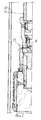
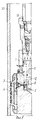
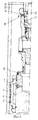
Конструкция пробки мостовой поясняется чертежами, где на фиг. 1 представлен общий вид устройства перед его спуском в скважину; на фиг. 2 то же при спуске в скважину; на фиг. 3 то же при установке пробки мостовой в скважине; на фиг. 4 то же при извлечении узла установки пробки мостовой из скважины. The construction of the bridge plug is illustrated in the drawings, where in FIG. 1 shows a General view of the device before it is lowered into the well; in FIG. 2 the same when descending into the well; in FIG. 3 the same when installing the bridge plug in the well; in FIG. 4 the same when removing the pavement plug installation unit from the well.
Пробка мостовая состоит (см. фиг. 1) из узла уплотнения и узла доставки последнего в скважину, которые включают корпус 1 с радиальным каналом 2 и обратным клапаном 3, уплотнительный элемент 4 со шлипсами 5 и уплотнительными резиновыми кольцами 6, переводник 7 в форме ступенчатого патрубка с радиальными каналами 8 и 9, срезной штифт 10, поршень 11, полость 12, заполненную пакерующей жидкостью. Перед спуском устройства в скважину к переводнику 7 подсоединяется переводник 13 с радиальными каналами 14 и 15, снабженный уравнительным клапаном 16 и сбивным клапаном 17, закрепленным на переводнике на срезной шпильке 18. The bridge plug (see Fig. 1) consists of a seal assembly and a delivery unit for the latter into the well, which include a housing 1 with a
Уплотнительные кольца, обеспечивающие герметизацию поверхностей сопряженных деталей пробки мостовой, на чертежах не показаны для удобства чтения графических материалов. O-rings for sealing surfaces of mating parts of the bridge plug are not shown in the drawings for the convenience of reading graphic materials.
Пробка мостовая устанавливается в скважине на трубах 19. The bridge plug is installed in the well on
Пробка мостовая работает следующим образом (см. фиг. 1-4). При спуске пробки мостовой в обсадную колонну 2 трубы 19 заполняются жидкостью из скважины через радиальный канал 15 при открытом уравнительном клапане 16. После спуска пробки мостовой на заданную глубину с устья скважины в трубах 19 создают избыточное давление Р1, которое передается в ступенчатом патрубке 7 с помощью поршня 11 на пакерующую жидкость 12. Величина давления Р2 в полости 12 во столько раз больше давления Р1, действующего сверху на поршень 11, во сколько раз площадь сечения проходного канала меньшей ступени патрубка 7 меньше площади сечения большей ступени патрубка.Bridge plug works as follows (see Fig. 1-4). When the bridge plug is lowered into the
Пакерующая жидкость из полости 12 под давлением Р2 поступает в полость уплотнительного элемента 4 через радиальные каналы 8, 2 и обратный клапан 3. При расчетном по величине давлении Р2 уплотнительный элемент надежно запакеровывается в обсадной колонне 20. После сброса избыточного давления Р1 в трубах 19 клапан 3 закрывается и в полости уплотнительного элемента 4, заполненного пакерующей жидкостью, действует избыточное давление Р2.Packing fluid from the
Узел доставки пробки мостовой извлекается из скважины после предварительного пуска в трубы 19 штока 21, который при падении на сбивной клапан 17 срезает шпильку 18, в результате чего открывается радиальный канал 14, обеспечивающий излив жидкости из труб 19 в скважину. Натяжением труб 19 на расчетную осевую нагрузку О срезают штифты 10 и извлекают узел установки пробки мостовой из скважины. Разобщение пластов в скважине обеспечивается уплотнительным узлом пробки мостовой за счет прижатия уплотнительным элементом 4 шлипсов 5 и резиновых колец 6 к внутренней поверхности обсадной колонны 20. ЫЫЫ1 ЫЫЫ2 ЫЫЫ3 The bridge plug delivery unit is removed from the well after preliminary start-up of the
Claims (1)
Priority Applications (1)
| Application Number | Priority Date | Filing Date | Title |
|---|---|---|---|
| SU5055215 RU2068942C1 (en) | 1992-07-17 | 1992-07-17 | Bridge plug |
Applications Claiming Priority (1)
| Application Number | Priority Date | Filing Date | Title |
|---|---|---|---|
| SU5055215 RU2068942C1 (en) | 1992-07-17 | 1992-07-17 | Bridge plug |
Publications (1)
| Publication Number | Publication Date |
|---|---|
| RU2068942C1 true RU2068942C1 (en) | 1996-11-10 |
Family
ID=21609828
Family Applications (1)
| Application Number | Title | Priority Date | Filing Date |
|---|---|---|---|
| SU5055215 RU2068942C1 (en) | 1992-07-17 | 1992-07-17 | Bridge plug |
Country Status (1)
| Country | Link |
|---|---|
| RU (1) | RU2068942C1 (en) |
Cited By (1)
| Publication number | Priority date | Publication date | Assignee | Title |
|---|---|---|---|---|
| RU2302511C2 (en) * | 2001-10-23 | 2007-07-10 | Шелл Интернэшнл Рисерч Маатсхаппий Б.В. | Device to execute operations in well |
-
1992
- 1992-07-17 RU SU5055215 patent/RU2068942C1/en active
Non-Patent Citations (1)
| Title |
|---|
| Авторское свидетельство СССР N 1533831, кл. Е 21 В 33/12, 1988. Авторское свидетельство СССР N 599047, кл. Е 21 В 33/12, 1975. * |
Cited By (1)
| Publication number | Priority date | Publication date | Assignee | Title |
|---|---|---|---|---|
| RU2302511C2 (en) * | 2001-10-23 | 2007-07-10 | Шелл Интернэшнл Рисерч Маатсхаппий Б.В. | Device to execute operations in well |
Similar Documents
| Publication | Publication Date | Title |
|---|---|---|
| US5152340A (en) | Hydraulic set packer and testing apparatus | |
| US4387767A (en) | Subsurface safety valve system with hydraulic packer | |
| US4993488A (en) | Well casing packers | |
| US4576235A (en) | Downhole relief valve | |
| US10927643B2 (en) | Operating a subsurface safety valve using a downhole pump | |
| EP0233750B1 (en) | Bar vent for downhole tool | |
| RU2068942C1 (en) | Bridge plug | |
| RU2081303C1 (en) | Underground equipment for operation of wells | |
| RU2098602C1 (en) | Arrangement for insulating strata | |
| RU2034998C1 (en) | Sucker-rod well pump unit | |
| RU2102577C1 (en) | Device for treating down-hole zone of well | |
| RU2092674C1 (en) | Device for hermetization of well head | |
| RU2045657C1 (en) | Bridge plug | |
| US2917000A (en) | Subsurface hydraulic pump assembly | |
| US4628997A (en) | Packoff | |
| RU2081999C1 (en) | Underground equipment for operating wells | |
| RU2698348C1 (en) | Packing unit of packer | |
| RU2047733C1 (en) | Universal blowout preventer | |
| RU2052662C1 (en) | Oil-well sucker-rod pump | |
| RU2105131C1 (en) | Hydraulic packer | |
| RU2055154C1 (en) | Bottom-hole packer-safety valve | |
| SU1606684A1 (en) | Pipe string to packer connecting/disconnecting device | |
| SU1709070A1 (en) | Well completion and operation device | |
| RU2140019C1 (en) | Electrical centrifugal-pump plant | |
| SU1222887A1 (en) | Well sucker-rod pumping plant |