RU2099103C1 - Method for controlling duration of stimulating pulse burst and device for carrying out electric stimulation of blood muscle pump - Google Patents
Method for controlling duration of stimulating pulse burst and device for carrying out electric stimulation of blood muscle pump Download PDFInfo
- Publication number
- RU2099103C1 RU2099103C1 RU93057592A RU93057592A RU2099103C1 RU 2099103 C1 RU2099103 C1 RU 2099103C1 RU 93057592 A RU93057592 A RU 93057592A RU 93057592 A RU93057592 A RU 93057592A RU 2099103 C1 RU2099103 C1 RU 2099103C1
- Authority
- RU
- Russia
- Prior art keywords
- duration
- pulse
- packet
- output
- burst
- Prior art date
Links
- 230000004936 stimulating effect Effects 0.000 title claims abstract description 44
- 238000000034 method Methods 0.000 title claims abstract description 33
- 210000003205 muscle Anatomy 0.000 title claims description 43
- 239000008280 blood Substances 0.000 title claims description 13
- 210000004369 blood Anatomy 0.000 title claims description 13
- 230000000638 stimulation Effects 0.000 title abstract 2
- 230000000747 cardiac effect Effects 0.000 claims abstract description 12
- 230000000903 blocking effect Effects 0.000 claims description 15
- 238000006243 chemical reaction Methods 0.000 claims description 9
- 230000000694 effects Effects 0.000 abstract description 14
- 230000033764 rhythmic process Effects 0.000 abstract description 10
- 239000003814 drug Substances 0.000 abstract description 6
- 230000001105 regulatory effect Effects 0.000 abstract description 5
- 230000009466 transformation Effects 0.000 abstract description 3
- 230000017531 blood circulation Effects 0.000 abstract description 2
- 238000007493 shaping process Methods 0.000 abstract 1
- 239000000126 substance Substances 0.000 abstract 1
- 230000015572 biosynthetic process Effects 0.000 description 6
- 230000001276 controlling effect Effects 0.000 description 6
- 230000000004 hemodynamic effect Effects 0.000 description 4
- 230000008602 contraction Effects 0.000 description 3
- 238000010586 diagram Methods 0.000 description 3
- 229940079593 drug Drugs 0.000 description 3
- 230000007717 exclusion Effects 0.000 description 3
- 238000007792 addition Methods 0.000 description 2
- 230000007831 electrophysiology Effects 0.000 description 2
- 238000002001 electrophysiology Methods 0.000 description 2
- 239000000463 material Substances 0.000 description 2
- 238000000844 transformation Methods 0.000 description 2
- 230000036772 blood pressure Effects 0.000 description 1
- 230000004087 circulation Effects 0.000 description 1
- 230000003205 diastolic effect Effects 0.000 description 1
- 238000009434 installation Methods 0.000 description 1
- 210000005240 left ventricle Anatomy 0.000 description 1
- 230000003387 muscular Effects 0.000 description 1
- 230000002107 myocardial effect Effects 0.000 description 1
- 238000004321 preservation Methods 0.000 description 1
- 210000002027 skeletal muscle Anatomy 0.000 description 1
Images
Landscapes
- Electrotherapy Devices (AREA)
Abstract
Description
Группа изобретений относится к медицине, а именно к вспомогательному кровообращению, в частности, к мышечным насосам крови, формируемым из собственных скелетных мышц пациента. The group of inventions relates to medicine, namely to auxiliary blood circulation, in particular, to muscle blood pumps formed from the patient’s own skeletal muscles.
Известен способ управления мышечным насосом крови при кардиомиопластике, заключающийся в синхронной с R зубцами подаче пачек стимулирующих импульсов на лоскут аутомышцы с программируемой извне кратностью синхронизации (Думчюс А.С. Кибиша Р.Т. Скучас И.Ю. и др. Разработка техники и методики миовентрикулопластики с использованием программируемой кардиосинхронизированной электронейростимуляции. Медицинская техника, 1988, N 4, с.11-25). Лоскут аутомышцы накладывается и фиксируется на выбранном отделе сердца. Мышечный (стимулирующий) электрод располагается на дистальном отделе мышцы, а кардиальный миокардиальный или эндокардиальный (воспринимающий R зубец) электрод располагается на одном из отделов сердца. There is a method of controlling a blood muscle pump during cardiomyoplasty, consisting in the supply of stimulating impulse bursts to the autologous muscle flap synchronously with R teeth with an externally programmed multiplicity of synchronization (Dumchus A.S. Kibisha R.T. Skuchas I.Yu. et al. Development of technology and methods myoventriculoplasty using programmable cardiosynchronized electrical neurostimulation. Medical technology, 1988, N 4, s.11-25). The autoparticle flap is superimposed and fixed on the selected part of the heart. The muscular (stimulating) electrode is located on the distal muscle, and the cardiac myocardial or endocardial (R-perceptible tooth) electrode is located on one of the parts of the heart.
К причинам, препятствующим достижению требуемого технического результата при использовании известного способа, относится то, что в известном способе длительность пачки стимулирующих импульсов остается постоянной при изменении частоты сердечных сокращений. Как известно, длительность систолы сердца зависит от частоты сердечных сокращений (Карпман В.Л. Фазовый анализ сердечной деятельности. М: Медицина, 1965, с. 275). Следовательно, длительность искусственно вызванного тетанического сокращения аутомышцы при кардиомиопластике должна не только соответствовать, но и адаптироваться к изменениям длительности кардиоцикла, что не учитывается в известном способе управления и может отрицательно влиять на гемодинамику. Например, слишком продолжительное тетаническое сокращение может мешать диастолическому наполнению левого желудочка, а недостаточное тетаническое сокращение существенно снижает гемодинамический эффект. The reasons that impede the achievement of the desired technical result when using the known method include the fact that in the known method, the duration of the stimulus burst remains constant when the heart rate changes. As you know, the duration of heart systole depends on the heart rate (Karpman VL Phase analysis of cardiac activity. M: Medicine, 1965, p. 275). Therefore, the duration of the artificially induced tetanic contraction of the auto muscle during cardiomyoplasty should not only correspond, but also adapt to changes in the duration of the cardiocycle, which is not taken into account in the known control method and can negatively affect hemodynamics. For example, too long a tetanic contraction can interfere with diastolic filling of the left ventricle, and insufficient tetanic contraction significantly reduces the hemodynamic effect.
Известен также способ регулирования длительности пачки стимулирующих импульсов при кардиомиопластике, заключающийся в программировании извне при помощи наружного программатора количества импульсов в пачке, поступающей на аутомышцу, и обеспечивающий, тем самым, возможность выбора желаемой длительности воздействия на аутомышцу (патент США N 4735205, кл. A 61 N 1/36, 1988). There is also a method of regulating the duration of a packet of stimulating pulses in cardiomyoplasty, which consists in programming from the outside using an external programmer the number of pulses in a packet delivered to the auto muscle, and thereby providing the possibility of choosing the desired duration of exposure to the auto muscle (US patent N 4735205, class A 61
К причинам, препятствующим достижению требуемого технического результата при использовании известного способа, относится то, что в известном способе после выбора и установки общей длительности воздействия на аутомышцу, эта длительность при изменении частоты сердечных сокращений остается неизменной, что по причинам, аналогичным указанным для предыдущего способа, существенно снижает гемодинамический эффект. The reasons that impede the achievement of the required technical result when using the known method include the fact that in the known method, after selecting and setting the total duration of exposure to the muscle, this duration remains unchanged when the heart rate changes, which, for reasons similar to those indicated for the previous method, significantly reduces the hemodynamic effect.
Наиболее близким способом того же назначения к заявленному способу в группе изобретений по совокупности признаков является способ регулирования длительности пачки стимулирующих импульсов, заключающийся в изменении числа импульсов в пачке в зависимости от частоты сердечных сокращений (авт. свид. N 1597200, кл. А 61 N 1/362, 1988), принят за прототип. Тем самым обеспечивается автоматическое регулирование общей длительности воздействия на аутомышцу в зависимости от частоты сердечных сокращений. The closest method of the same purpose to the claimed method in the group of inventions according to the totality of features is a method for controlling the duration of a packet of stimulating pulses, which consists in changing the number of pulses in a packet depending on the heart rate (ed. Certificate N 1597200, class A 61
К причинам, препятствующим достижению требуемого технического результата при использовании известного способа, принятого за прототип, относится следующее. В известном способе регулирование общей длительности воздействия на аутомышцу осуществляется путем автоматического учета введенной усредненной зависимости длительности пачки стимулирующих импульсов от частоты сердечных сокращений. При этом измеряют длительность каждого текущего кардиоцикла и устанавливают в следующем кардиоцикле длительность пачки, равную определенной части измеренной длительности предыдущего кардиоцикла. Значение части кардиоцикла в данном способе определяют по одной из известных зависимостей между частотой сердечных сокращений и длительностью общей систолы сердца (например, Капман В.Л. Фазовый анализ сердечной деятельности. М: Медицина, 1965, с. 275). Однако, в имплантируемых аппаратах для уменьшения потребления тока частота следования импульсов в пачке выбирается достаточно низкой и, исходя из электрофизиологии мышц, для тренированной мышцы может доходить до 10 Гц. Поэтому дискретность регулирования длительности пачки путем изменения количества импульсов оказывается большой. Действительно, шаг дискретности регулирования в этом случае будет обратно пропорционален частоте следования импульсов в пачке и может достигать значения 100 мс. Помимо этого, в данном способе неизбежно скачкообразное изменение длительности общего воздействия на аутомышцу при изменении ритма сердца. The reasons that impede the achievement of the required technical result when using the known method adopted for the prototype include the following. In the known method, the regulation of the total duration of exposure to the muscle is carried out by automatically taking into account the introduced average dependence of the duration of the burst of stimulating pulses on the heart rate. In this case, the duration of each current cardiocycle is measured and the duration of the pack equal to a certain part of the measured duration of the previous cardiocycle is set in the next cardiocycle. The value of the part of the cardiocycle in this method is determined by one of the known relationships between the heart rate and the duration of the total systole of the heart (for example, Kapman VL Phase analysis of cardiac activity. M: Medicine, 1965, p. 275). However, in implantable devices, in order to reduce current consumption, the pulse repetition rate in the pack is selected to be quite low and, based on the electrophysiology of the muscles, can reach 10 Hz for a trained muscle. Therefore, the discreteness of the regulation of the duration of the pack by changing the number of pulses is large. Indeed, the step of regulation discreteness in this case will be inversely proportional to the pulse repetition rate in the packet and can reach 100 ms. In addition, in this method, an inevitable abrupt change in the duration of the general effect on the auto muscle with a change in heart rhythm is inevitable.
Известен электростимулятор мышечного насоса крови, содержащий блок управления, кардинальный и мышечный каналы (патент США N 4735205, кл. А 61 N 1/36, 1988). Кардинальный канал электростимулятора включает в себя входной усилитель, элемент и источник одиночных стимулирующих импульсов. Мышечный канал электростимулятора содержит делитель кардиоциклов, блок задержки, формирователь пачек стимулирующих импульсов и выходной каскад. Блок управления включает в себя узлы приема управляющих кодов от внешнего программатора, которые преобразуют эти коды в сигналы, устанавливающие параметры блоков кардиального и мышечного каналов электростимулятора. Таким образом, в данном электростимуляторе при помощи внешнего программатора возможны выбор и установка общей длительности воздействия на аутомышцу, а также повторное изменение этой длительности. Known electrical stimulator of a muscle blood pump containing a control unit, cardinal and muscle channels (US patent N 4735205, CL A 61
К причинам, препятствующим достижению требуемого технического результата при использовании известного устройства, относится то, что в известном устройстве выбор, установка и изменение общей длительности воздействия на аутомышцу осуществляются вручную оператором при помощи внешнего программатора, а в промежутках между программированием общая длительность воздействия на аутомышцу при изменении частоты сердечных сокращений остается неизменной, что по причинам, аналогичным для вышеуказанных способов существенно снижает гемодинамический эффект. The reasons that impede the achievement of the required technical result when using the known device include the fact that in the known device, the selection, installation and change of the total duration of exposure to the auto muscle is carried out manually by the operator using an external programmer, and in the intervals between programming the total duration of exposure to the auto muscle when changing heart rate remains unchanged, which for reasons similar to the above methods significantly reduces hemodynamic sky effect.
Наиболее близким устройством того же назначения к заявленному устройству в группе изобретений по совокупности признаков является электростимулятор мышечного насоса крови, содержащий связанные между собой блок преобразования сигнала, формирователь интервала блокировки, делитель кардиоциклов, генератор стимулирующих импульсов, выходной каскад, блок измерения длительности кардиоциклов и блок регулирования длительности пачки стимулирующих импульсов (авт. свид. N 1597200, кл. А 61 N 1/362, 1988). Данный электростимулятор принят за прототип. The closest device of the same purpose to the claimed device in the group of inventions according to the totality of signs is an electrostimulator of a muscle blood pump containing a signal conversion unit, a blocking interval driver, a cardiocycle divider, stimulating pulse generator, an output stage, a cardiocycle duration measuring unit, and a regulation unit the duration of a packet of stimulating pulses (ed. certificate. N 1597200, class A 61
К причинам, препятствующим достижению требуемого технического результата при использовании известного устройства, принятого за прототип, относится следующее. В известном устройстве регулирование общей длительности воздействия на аутомышцу осуществляется путем автоматического учета в блоке регулирования общей длительности воздействия введенной усредненной зависимости длительности пачки стимулирующих импульсов от частоты сердечных сокращений. При этом блок измерения длительности кардиоциклов производит измерение длительности каждого текущего кардиоцикла и вырабатывает управляющий сигнал, по которому блок регулирования общей длительности воздействия устанавливает в следующем кардиоцикле длительность пачки, равную определенной части измеренной длительности предыдущего кардиоцикла. Значение части кардиоцикла в данном способе жестко задано в блоке регулирования общей длительности воздействия по одной из известных зависимостей между частотой сердечных сокращений и длительностью общей систолы сердца (например, Карпман В.Л. Фазовый анализ сердечной деятельности. М: Медицина, 1965, с. 275). Однако, в имплантируемых аппаратах для уменьшения потребления тока частота следования импульсов в пачке выбирается достаточно низкой и, исходя из электрофизиологии мышц, для тренированной мышцы может доходить до 10 Гц. Поэтому дискретность регулирования длительности пачки путем изменения количества импульсов оказывается большой. Действительно, шаг дискретности регулирования в этом случае будет обратно пропорционален частоте следования импульсов в пачке и может достигать значения 100 мс. Помимо этого, в данном устройстве неизбежно скачкообразное изменение длительности общего воздействия на аутомышцу при изменении ритма сердца. The reasons that impede the achievement of the required technical result when using the known device adopted for the prototype include the following. In the known device, the control of the total duration of exposure to the muscle is carried out by automatically taking into account in the control unit the total duration of exposure of the introduced average dependence of the duration of the burst of stimulating pulses on the heart rate. In this case, the cardiocycle duration measuring unit measures the duration of each current cardiocycle and generates a control signal, according to which the unit for controlling the total duration of exposure sets in the next cardiocycle the duration of the pack equal to a certain part of the measured duration of the previous cardiocycle. The value of the part of the cardiocycle in this method is rigidly set in the control unit for the total duration of exposure according to one of the known relationships between the heart rate and the duration of the total systole of the heart (for example, Karpman VL Phase analysis of cardiac activity. M: Medicine, 1965, p. 275 ) However, in implantable devices, in order to reduce current consumption, the pulse repetition rate in the pack is selected to be quite low and, based on the electrophysiology of the muscles, can reach 10 Hz for a trained muscle. Therefore, the discreteness of the regulation of the duration of the pack by changing the number of pulses is large. Indeed, the step of regulation discreteness in this case will be inversely proportional to the pulse repetition rate in the packet and can reach 100 ms. In addition, in this device, an inevitable abrupt change in the duration of the general effect on the auto muscle with a change in heart rhythm is inevitable.
Сущность изобретения заключается в следующем. Единая задача, на решение которой направлена заявленная группа изобретений заключается в повышении точности регулирования длительности общего воздействия на аутомышцу и исключении скачкообразного изменения этой длительности при изменении ритма сердца. The invention consists in the following. The single task to be solved by the claimed group of inventions is to increase the accuracy of regulation of the duration of the general effect on the aut muscle and the exclusion of an abrupt change in this duration with a change in the heart rhythm.
Единый технический результат, который может быть получен при осуществлении группы изобретений заключается в уменьшении дискретности регулирования длительности пачки стимулирующих импульсов при сохранении экономичности формирования пачек. A single technical result that can be obtained by implementing a group of inventions is to reduce the discreteness of regulation of the duration of a packet of stimulating pulses while maintaining the efficiency of the formation of packs.
Указанный единый технический результат при осуществлении группы изобретений по объекту-способу достигается тем, что в известном способе регулирования длительности пачки стимулирующих импульсов, заключающемся в изменении числа импульсов в пачке, при установке границы длительности пачки приходящейся во временной оси на некоторую точку между (n-1)-ым импульсом и n-ым реальным или экстраполированным импульсом первоначальной пачки, с 1-го по (n-1)-ый импульсы пачки оставляют неизменными, а n-ый импульс перемещают по временной оси в данную точку и устанавливают его последним импульсом в пачке. The specified single technical result in the implementation of the group of inventions according to the object-method is achieved by the fact that in the known method of regulating the duration of a packet of stimulating pulses, which consists in changing the number of pulses in a packet, when setting the border of the duration of the packet falling in the time axis at some point between (n-1 ) of the pulse and the nth real or extrapolated pulse of the initial packet, from the 1st to the (n-1 )th pulse of the packet are left unchanged, and the nth pulse is moved along the time axis to this point set it the last pulse in a pack.
Предложенная в данном способе последовательность действий позволяет исключить дискретность в регулировании длительности пачки стимулирующих импульсов. Действительно, если вычисленная граница длительности пачки приходится во временной оси на некоторую точку между (n-1)-ым импульсом и n-ым реальным или экстраполированным импульсом первоначальной пачки, то в прототипе произошло бы формирование пачки из (n-1)-го импульса с первоначальными параметрами. В предложенном способе кроме этих (n-1)-ых импульсов формируется n-ый импульс, который размещают по временной оси в требуемой точке, соответствующей точке вычисленной длительности пачки. Тем самым достигается уменьшение дискретности регулирования длительности пачки стимулирующих импульсов. The sequence of actions proposed in this method eliminates discreteness in the regulation of the duration of a packet of stimulating pulses. Indeed, if the calculated boundary of the duration of the packet falls on the time axis at some point between the (n-1) th pulse and the n-th real or extrapolated pulse of the initial packet, then in the prototype a packet would be formed from the (n-1) -th pulse with initial parameters. In the proposed method, in addition to these (n-1) th pulses, the n-th pulse is formed, which is placed along the time axis at the desired point corresponding to the point of the calculated burst duration. Thereby, a decrease in the discreteness of regulation of the duration of a packet of stimulating pulses is achieved.
Указанный единый технический результат при осуществлении группы изобретений по объекту-устройству достигается тем, что в известном электростимуляторе мышечного насоса крови, содержащем связанные между собой блок преобразования сигнала, формирователь интервала блокировки, делитель кардиоциклов, генератор стимулирующих импульсов, выходной каскад, блок измерения длительности кардиоциклов и блок регулирования длительности пачки стимулирующих импульсов, дополнительно введены логический элемент ИЛИ, установленный в разрыв между первым выходом генератора стимулирующих импульсов и входом выходного каскада, и последовательно соединенные формирователь точной длительности пачки и формирователь последнего импульса пачки, причем вход формирователя точной длительности пачки связан со вторым выходом формирователя интервала блокировки, а выход формирователя последнего импульса пачки подключен ко второму входу логического элемента ИЛИ. The specified single technical result in the implementation of the group of inventions for the object device is achieved by the fact that in the known electrostimulator of a muscle blood pump, containing a signal conversion unit, a blocking interval driver, a cardiocycle divider, a stimulating pulse generator, an output stage, a cardiocycle duration measuring unit and block for regulating the duration of a packet of stimulating pulses, an additional OR logic element is installed, installed in the gap between the first the output of the stimulating pulse generator and the input of the output stage, and the shaper of the exact burst duration and the shaper of the last burst pulse connected in series, the input of the shaper of the exact burst duration being connected to the second output of the blocking interval shaper, and the output of the last burst pulse shaper connected to the second input of the OR logic element .
Предложенный электростимулятор, содержащий последовательно соединенные блок преобразования сигнала, формирователь интервала блокировки, делитель кардиоциклов, генератор стимулирующих импульсов, элемент ИЛИ и выходной каскад, а также последовательно соединенные блок измерения длительности кардиоциклов и блок регулирования длительности пачки стимулирующих импульсов, причем вход блока преобразования сигнала соединен кардиальным электродом с сердцем, выход выходного каскада связан мышечным электродом с лоскутом аутомышцы мышечного насоса крови, вход блока измерения длительности кардиоциклов подключен ко второму выходу формирователя интервала блокировки, выход блока регулирования длительности пачки стимулирующих импульсов соединен со входом задания числа импульсов в пачке генератора стимулирующих импульсов, а также последовательно соединенные формирователь точной длительности пачки и формирователь последнего импульса пачки, причем вход формирователя точной длительности пачки связан со вторым выходом формирователя интервала блокировки, а выход формирователя последнего импульса пачки подключен ко второму входу логического элемента ИЛИ, обеспечивает следующее. Осуществление в данном устройстве последовательно выделения R-зубцов, измерения R-R интервалов и формирования пачки стимулирующих импульсов длительностью равной заданной части измеренного R-R интервала, с размещением последнего импульса в точке временной оси, соответствующей точно вычисленной границе пачки, позволяет повысить точность регулирования длительности общего воздействия на аутомышцу и исключить скачкообразное изменение длительности общего воздействия на аутомышцу при изменении ритма сердца. The proposed electrical stimulator containing a serially connected signal conversion unit, a blocking interval driver, a cardiocycle divider, a stimulating pulse generator, an OR element and an output stage, as well as a series-connected cardiocycle duration measuring unit and a stimulating pulse train duration control unit, the input of the signal conversion unit being connected by a cardiac an electrode with a heart, the output of the output stage is connected by a muscle electrode to a muscle blood pump, the input of the cardiocycle duration measuring unit is connected to the second output of the blocking interval shaper, the output of the stimulating pulse train duration control unit is connected to the input of the number of pulses in the stimulating pulse generator burst, as well as the shaper of the exact burst duration and the last pulse shaper of the burst, the shaper input of the exact burst duration is connected to the second output of the blocking interval shaper, and the output is formed A last pulse burst is connected to the second input of the OR gate provides the following. The implementation in this device of sequentially isolating R-waves, measuring RR intervals and forming a packet of stimulating pulses with a duration equal to a given part of the measured RR interval, with the placement of the last pulse at a point on the time axis corresponding to a precisely calculated border of the packet, improves the accuracy of controlling the duration of the total effect on the aut muscle and to exclude an abrupt change in the duration of the general effect on the auto muscle when the heart rhythm changes.
Заявленная группа изобретения соответствует требованию единства изобретения, поскольку группа равнообъектных изобретений образует единый изобретательский замысел, причем один из заявленных объектов группы - устройство предназначено для осуществления другого заявленного объекта группы способа при этом оба объекта заявленной группы изобретений направлены на решение одной и той же задачи с получением единого технического результата. The claimed group of inventions meets the requirement of the unity of the invention, since the group of equally object inventions forms a single inventive concept, moreover, one of the claimed objects of the group - the device is designed to implement another claimed object of the method group, while both objects of the claimed group of inventions are aimed at solving the same problem with obtaining a single technical result.
Проведенный заявителем анализ уровня техники, включающий поиск по патентным и научно-техническим источникам информации и выявление источников, содержащих сведения об аналогах заявленной группы изобретений как для объекта-устройства, так для объекта-способа, позволил установить, что заявителем не обнаружены аналоги, как для способа, так и для устройства заявленной группы, характеризующиеся признаками, идентичными всем существенным признакам как способа, так и устройства заявленной группы изобретений, а определение из перечня выявленных аналогов прототипов как для способа, так и для устройства как наиболее близких по совокупности признаков аналогов, позволил выявить совокупность существенных по отношению к усматриваемому заявителем техническому результату отличительных признаков для каждого из заявленных объектов группы, изложенных в формуле изобретения. The analysis of the prior art by the applicant, including a search by patent and scientific and technical sources of information and identification of sources containing information about analogues of the claimed group of inventions for both the device object and the method object, made it possible to establish that the applicant did not find analogues, as for method, and for the device of the claimed group, characterized by features identical to all the essential features of both the method and the device of the claimed group of inventions, and the definition from the list identified x analogues prototype for method and device as the closest in totality of features analogues revealed a set of essential with respect to the applicant sees the technical effect characteristic features for each of the stated objects of the group set out in the claims.
Следовательно, каждый из объектов заявленной группы изобретений соответствует требованию "новизна" по действующему законодательству. Для проверки соответствия каждого из объектов заявленной группы изобретений требованию изобретательского уровня заявитель провел дополнительный поиск известных решений, с целью выявления признаков, совпадающих с отличительными от выбранных прототипов признаками для каждого из объектов заявленной группы изобретений, результаты которого показывают, что каждый из объектов заявленной группы изобретений для специалиста не следует явным образом из известного уровня техники, поскольку из уровня техники, определенного заявителем, не выявлено влияние предусматриваемых существенными признаками каждого из объектов заявленной группы изобретений преобразований на достижение технического результата, в частности, в каждом из объектов заявленной группы изобретений не предусматриваются следующие преобразования:
дополнение известного средства какой-либо известной частью, присоединяемой к нему по известным правилам, для достижения технического результата, в отношении которого установлено влияние именно таких дополнений;
замена какой-либо части известного средства другой известной частью для достижения технического результата, в отношении которого установлено влияние именно такой замены;
исключение какой-либо части средства с одновременным исключением обусловленной ее наличием функции и достижением при этом обычного для такого случая результата;
увеличение количества однотипных элементов для усиления технического результата, обусловленного наличием в средстве именно таких элементов;
выполнение известного средства или его части из известного материала для достижения технического результата, обусловленного известными свойствами материала;
создание средства, состоящего из известных частей, выбор которых и связь между ними осуществлены на основании известных правил, и достигаемый при этом технический результат обусловлен только известными свойствами частей этого объекта и связей между ними.Therefore, each of the objects of the claimed group of inventions meets the requirement of "novelty" under the current legislation. To verify the conformity of each of the objects of the claimed group of inventions to the requirements of the inventive step, the applicant conducted an additional search for known solutions in order to identify features that match the distinctive features of the selected prototypes for each of the objects of the claimed group of inventions, the results of which show that each of the objects of the claimed group of inventions for a specialist it does not follow explicitly from the prior art, since from the prior art determined by the applicant, not identified the influence provided for by the essential features of each of the objects of the claimed group of inventions of the transformations on the achievement of the technical result is provided, in particular, the following transformations are not provided for in each of the objects of the claimed group of inventions:
the addition of a known means by any known part, attached to it according to known rules, to achieve a technical result, in respect of which the influence of such additions is established;
the replacement of any part of the known means with another known part to achieve a technical result, in respect of which the effect of such a replacement is established;
the exclusion of any part of the tool with the simultaneous exclusion of the function due to its presence and the achievement of the usual result for this case;
the increase in the number of elements of the same type to enhance the technical result due to the presence in the tool of just such elements;
the implementation of a known tool or part thereof from a known material to achieve a technical result due to the known properties of the material;
the creation of a tool consisting of known parts, the choice of which and the relationship between them are based on known rules, and the technical result achieved in this case is due only to the known properties of the parts of this object and the relationships between them.
Следовательно, каждый из объектов заявленной группы изобретений соответствует требованию "изобретательский уровень" по действующему законодательству. Therefore, each of the objects of the claimed group of inventions meets the requirement of "inventive step" under applicable law.
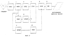
На фиг.1 и 2 представлена схема устройства в заявленной группе изобретений, где на фиг. 1 изображена функциональная схема электростимулятора мышечного насоса крови, принятого за прототип, на фиг. 2 функциональная схема электростимулятора мышечного насоса крови в объеме п.2 формулы изобретения. 1 and 2 show a diagram of a device in the claimed group of inventions, where in FIG. 1 shows a functional diagram of an electrostimulator of a muscle blood pump adopted as a prototype; FIG. 2 is a functional diagram of an electric stimulator of a muscle blood pump in the scope of
Сведения, подтверждающие возможность осуществления каждого из объектов заявленной группы изобретений с получением вышеуказанного технического результата, заключаются в следующем. Information confirming the possibility of implementing each of the objects of the claimed group of inventions with the receipt of the above technical result are as follows.
По объекту-способу. Способ регулирования длительности пачки стимулирующих импульсов заключается в том, что при установке границы длительности пачки приходящейся во временной оси на некоторую точку между (n-1)-ым импульсом и n-ым реальным или экстраполированным импульсом первоначальной пачки, с 1-го по (n-1)-ый импульсы пачки оставляют неизменными, а n-ый импульс перемещают по временной оси в данную точку и устанавливают его последним импульсом в пачке. Это обеспечивает повышение точности установки длительности пачки. Кроме того, изменение длительности пачки при изменении ритма сердца от одного рабочего цикла к другому осуществляется плавно. Тем самым достигается повышение точности регулирования длительности общего воздействия на аутомышцу и исключаются скачкообразные изменения этой длительности при изменении ритма сердца. According to the object method. A method for controlling the duration of a burst of stimulating pulses is that when setting the boundary of the burst duration falling in the time axis to a certain point between the (n-1) th pulse and the n-th real or extrapolated pulse of the initial burst, from the 1st to (n The -1th pulse of the packet is left unchanged, and the nth pulse is moved along the time axis to this point and set with the last pulse in the packet. This provides increased accuracy in setting the duration of the pack. In addition, the change in the duration of the pack when changing the rhythm of the heart from one working cycle to another is carried out smoothly. Thereby, an increase in the accuracy of regulation of the duration of the total effect on the aut muscle is achieved and spasmodic changes in this duration with a change in the heart rhythm are eliminated.
По объекту-устройству. Электростимулятор мышечного насоса крови содержит последовательно соединенные блок 1 преобразования сигнала, формирователь 2 интервала блокировки, делитель 3 кардиоциклов, генератор 4 стимулирующих импульсов, элемент 5 ИЛИ и выходной каскад 6, а также последовательно соединенные блок 7 измерения длительности кардиоциклов и блок 8 регулирования длительности пачки стимулирующих импульсов, причем вход блока 1 преобразования сигнала соединен кардиальным электродом с сердцем, выход выходного каскада 6 связан мышечным электродом с лоскутом аутомышцы мышечного насоса крови, вход блока 7 измерения длительности кардиоциклов подключен ко второму выходу формирователя 2 интервала блокировки, выход блока 8 регулирования длительности пачки стимулирующих импульсов соединен со входом задания числа импульсов в пачке генератора 4 стимулирующих импульсов, а также последовательно соединенные формирователь 9 точной длительности пачки и формирователь 10 последнего импульса пачки, причем вход формирователя 9 точной длительности пачки связан со вторым выходом формирователя 2 интервала блокировки, а выход формирователя 10 последнего импульса пачки подключен ко второму входу логического элемента 5 ИЛИ. By device object. The stimulator of the muscle blood pump contains a
Электростимулятор работает следующим образом. Электрокардиосигнал поступает на вход блока 1 преобразования сигнала. В этом блоке происходит выделение R-зубцов электрокардиосигнала и формирование на выходе блока сигналов синхронизации, поступающих на вход блока 2 формирователя интервала блокировки. Блок 2 формирования интервала блокировки осуществляет блокировку электростимулятора по входу в течение определенного временного интервала. Тем самым исключаются ложные срабатывания электростимулятора от выходных стимулирующих импульсов, попадающих на вход стимулятора по проводящей среде. При этом на выходах блока 2 формируются импульсы синхронизации, соответствующие только тем R зубцам входного электрокардиосигнала, которые не попали в интервал блокировки. С первого выхода блока 2 формирования интервала блокировки сигнал синхронизации поступает на вход делителя 3 кардиоциклов, который обеспечивает заданную кратность синхронизации по отношению к входным сигналам синхронизации. С выхода делителя 3 импульс синхронизации поступает на тактовый вход генератора 4 стимулирующих импульсов и запускает его. При этом на первом выходе генератора 4 формируется пачка импульсов с заданными параметрами. Количество импульсов в пачке, а, следовательно, и ее длительность, определяется кодом, установленным на входе D генератора 4 стимулирующих импульсов. С выхода генератора 4 стимулирующие импульсы поступают на первый вход элемента 5 ИЛИ. С выхода элемента 5 ИЛИ стимулирующие импульсы поступают на вход выходного каскада 6. На выходе выходного каскада формируются стимулирующие импульсы заданной амплитуды и полярности. С выхода выходного каскада 6 через мышечный (стимулирующий) электрод стимулирующие импульсы поступают на аутомышцу насоса крови. The stimulator works as follows. The electrocardiological signal is input to the
Со второго выхода блока 2 формирования интервала блокировки импульс синхронизации поступает на первый вход блока 7 измерения длительности кардиоцикла. На выходе блока 7 формируется код, соответствующий длительности последнего кардиоцикла. С выхода блока 7 измерения длительности кардиоцикла код поступает на вход блока 8 регулирования длительности пачки. На выходе блока 8 формируется код, соответствующий заданной части измеренного R-R интервала. С выхода блока 8 код поступает на вход D генератора 4 стимулирующих импульсов. Со второго выхода блока 2 формирования интервала блокировки импульс синхронизации поступает на вход блока 9 формирования точной длительности пачки, в котором формируется импульс, точно соответствующий по длительности заданной части кардиоцикла. По окончании этого импульса, который поступает с выхода блока 9 формирования точной длительности пачки на вход блока 10 формирования последнего импульса, на выходе блока 10 формируется последний импульс пачки. С выхода блока 10 импульс поступает на второй вход элемента 5 ИЛИ, в котором происходит объединение первых импульсов пачки и последнего импульса. From the second output of the
Это обеспечивает повышение точности установки длительности пачки. Кроме того, изменение длительности пачки при изменении ритма сердца от одного рабочего цикла к другому осуществляется плавно. Тем самым, достигается повышение точности регулирования длительности общего воздействия на аутомышцу и исключаются скачкообразные изменения этой длительности при изменении ритма сердца. Кроме того, в предложенном устройстве за счет сохранения неизменной частоты следования импульсов в основной части пачки стимулирующих импульсов обеспечивается высокая экономичность формирования пачек. This provides increased accuracy in setting the duration of the pack. In addition, the change in the duration of the pack when changing the rhythm of the heart from one working cycle to another is carried out smoothly. Thereby, an increase in the accuracy of regulation of the duration of the general effect on the auto muscle is achieved, and spasmodic changes in this duration with a change in the heart rhythm are eliminated. In addition, in the proposed device due to the preservation of a constant pulse repetition rate in the main part of the stimulating pulse train, high efficiency of packet formation is ensured.
Таким образом, вышеизложенные сведения свидетельствуют о выполнении при использовании заявленного изобретения следующей совокупности условия:
средство, воплощающее заявленное изобретение при его осуществлении, предназначено для использования в промышленности, именно, в медицине в аппаратуре для вспомогательного кровообращения;
для заявленного изобретения в том виде, как оно охарактеризовано в независимом пункте нижеизложенной формулы изобретения, подтверждена возможность его осуществления с помощью вышеописанных в заявке или известных до даты приоритета средств и методов;
средство, воплощающее заявленное изобретение при его осуществлении, способно обеспечить достижение усматриваемого заявителем технического результата.Thus, the above information indicates that when using the claimed invention the following combination of conditions:
the tool embodying the claimed invention in its implementation is intended for use in industry, namely, in medicine, in equipment for auxiliary circulation;
for the claimed invention as described in the independent clause of the claims below, the possibility of its implementation using the means and methods described above or known prior to the priority date is confirmed;
means embodying the claimed invention in its implementation, is capable of achieving the achievement of the technical result perceived by the applicant.
Следовательно, заявленное изобретение соответствует требованию "промышленная применимость" по действующему законодательству. Therefore, the claimed invention meets the requirement of "industrial applicability" under applicable law.
Claims (2)
Priority Applications (1)
| Application Number | Priority Date | Filing Date | Title |
|---|---|---|---|
| RU93057592A RU2099103C1 (en) | 1993-12-24 | 1993-12-24 | Method for controlling duration of stimulating pulse burst and device for carrying out electric stimulation of blood muscle pump |
Applications Claiming Priority (1)
| Application Number | Priority Date | Filing Date | Title |
|---|---|---|---|
| RU93057592A RU2099103C1 (en) | 1993-12-24 | 1993-12-24 | Method for controlling duration of stimulating pulse burst and device for carrying out electric stimulation of blood muscle pump |
Publications (2)
| Publication Number | Publication Date |
|---|---|
| RU93057592A RU93057592A (en) | 1997-03-27 |
| RU2099103C1 true RU2099103C1 (en) | 1997-12-20 |
Family
ID=20150853
Family Applications (1)
| Application Number | Title | Priority Date | Filing Date |
|---|---|---|---|
| RU93057592A RU2099103C1 (en) | 1993-12-24 | 1993-12-24 | Method for controlling duration of stimulating pulse burst and device for carrying out electric stimulation of blood muscle pump |
Country Status (1)
| Country | Link |
|---|---|
| RU (1) | RU2099103C1 (en) |
Cited By (1)
| Publication number | Priority date | Publication date | Assignee | Title |
|---|---|---|---|---|
| RU2397694C2 (en) * | 2003-03-17 | 2010-08-27 | Маттео БОНАН | Automated method for determining existence of heart contractions |
-
1993
- 1993-12-24 RU RU93057592A patent/RU2099103C1/en active
Non-Patent Citations (1)
| Title |
|---|
| SU, авторское свидетельство N 1597200, A 61 N 1/362, 1988. * |
Cited By (1)
| Publication number | Priority date | Publication date | Assignee | Title |
|---|---|---|---|---|
| RU2397694C2 (en) * | 2003-03-17 | 2010-08-27 | Маттео БОНАН | Automated method for determining existence of heart contractions |
Similar Documents
| Publication | Publication Date | Title |
|---|---|---|
| US4181133A (en) | Programmable tachycardia pacer | |
| DE69116846T2 (en) | Pacemaker with automatic programming of the AV period to optimize the AV period of the left heart | |
| DE69836991T2 (en) | Four-chamber pacemaker system for optimizing cardiac output | |
| US7555340B2 (en) | Electrogram morphology-based CRT optimization | |
| DE69926502T2 (en) | HEART RINSING USING ADJUSTABLE ATRIO-VENTRICULAR DELAY INTERVALS | |
| DE69819526T2 (en) | HEART IRRITATION WITH MULTIPLE IRRITATION THERMAL CHARACTERISTICS | |
| EP0596598A2 (en) | Cardiac rhythm management device with automatic optimization of performance related pacing parameters | |
| DE602004006228T2 (en) | IDENTIFICATION OF ALTERNATIVE T-WAVES | |
| EP0677302A2 (en) | Pacemaker programmer-based automatic retrograde conduction measurement | |
| JPS6150465B2 (en) | ||
| US6064913A (en) | Multiple pulse stimulation | |
| RU2099103C1 (en) | Method for controlling duration of stimulating pulse burst and device for carrying out electric stimulation of blood muscle pump | |
| EP2482924B1 (en) | Heart stimulating device with selecting optimal electrode configuration | |
| RU2070060C1 (en) | Method of control of muscular blood pump and muscular blood pump electrostimulator | |
| RU93057592A (en) | METHOD OF REGULATING THE DURATION OF A STUFF OF STIMULATING PULSES AND ELECTRIC STIMULATOR OF THE MUSCULAR BLOOD PUMP | |
| SU1597200A1 (en) | Muscular blood pump electrostimulator | |
| JP2804138B2 (en) | PMT detection pacemaker | |
| SU829094A1 (en) | Device for automatic search of stimulating pulse amplitude | |
| SU725674A1 (en) | Cardiostimulant | |
| RU2088272C1 (en) | Method for postoperative myocardial regeneration | |
| SU556816A1 (en) | Cardiac pacemaker | |
| SU1695943A1 (en) | Implantable electromyostimulator | |
| SU719634A1 (en) | Device for lowering the cardiac rithm | |
| SU1052238A1 (en) | Apparatus for monitoring electrocardiostimulation | |
| SU374088A1 (en) | Cardio stimulator |