RU2112103C1 - Method of laying continuous welded rail lengths - Google Patents
Method of laying continuous welded rail lengths Download PDFInfo
- Publication number
- RU2112103C1 RU2112103C1 RU97109504A RU97109504A RU2112103C1 RU 2112103 C1 RU2112103 C1 RU 2112103C1 RU 97109504 A RU97109504 A RU 97109504A RU 97109504 A RU97109504 A RU 97109504A RU 2112103 C1 RU2112103 C1 RU 2112103C1
- Authority
- RU
- Russia
- Prior art keywords
- rail
- lash
- length
- laying
- whip
- Prior art date
Links
- 238000000034 method Methods 0.000 title claims description 11
- 229910000831 Steel Inorganic materials 0.000 claims description 4
- 239000010959 steel Substances 0.000 claims description 4
- 239000000126 substance Substances 0.000 abstract 1
- 238000010835 comparative analysis Methods 0.000 description 1
- 230000003247 decreasing effect Effects 0.000 description 1
- 238000010586 diagram Methods 0.000 description 1
- 238000009434 installation Methods 0.000 description 1
- 238000012544 monitoring process Methods 0.000 description 1
- 238000005096 rolling process Methods 0.000 description 1
Images
Landscapes
- Machines For Laying And Maintaining Railways (AREA)
Abstract
Description
Изобретение относится к железнодорожным путям и может быть использовано при укладке рельсовых плетей бесстыкового пути на подрельсовое основание с одновременным вводом их в расчетный температурный интервал закрепления. The invention relates to railways and can be used when laying rail lashes of the welded jointless track on a rail base with their simultaneous entry into the calculated temperature fixing interval.
Наиболее близким к изобретению является способ укладки длинномерной рельсовой плети, заключающийся в том, что укладывают рельсовую плеть подошвой на ролики, устанавливаемые на подрельсовом основании, жестко закрепляют один ее конец, прикладывают к другому ее концу продольную растягивающую силу такой величины, чтобы получить принудительное изменение длины рельсовой плети, а, следовательно, и расчетные значения напряжений, соответствующих принятой расчетной температуре закрепления рельсовой плети, удаляют ролики из-под подошвы рельсовой плети и закрепляют рельсовую плеть на подрельсовом основании сначала ее концевые участки, а затем среднюю часть (авт. св. СССР N 192237, кл. E 01 B 29/17, 1967). Closest to the invention is a method of laying a long rail whip, which consists in laying the rail whip with the sole on the rollers mounted on the rail base, rigidly fix one end thereof, apply a longitudinal tensile force of such magnitude to the other end to obtain a forced change in length of the rail lash, and, consequently, the calculated values of the stresses corresponding to the accepted design temperature of fastening the rail lash, remove the rollers from under the sole of the rail second runner rail and is fixed on the rail base whip its first end portions, and then the middle part (auth. binding. USSR N 192237, Cl. E 01 B 29/17, 1967).
Недостатком данного способа является невозможность получения равномерных значений напряжений по длине плети, соответствующих принятой расчетной температуре закрепления плети на постоянный режим эксплуатации, из-за наличия погонного сопротивления рельсовой плети, вызываемого трением качения подошвы рельса (например, отчет НИИЖТа по НИР 89/77, госрегистрация 77062562, инвентарный номер Б875401, c. 18 - 21). The disadvantage of this method is the impossibility of obtaining uniform voltage values along the length of the lash, corresponding to the accepted design temperature of fastening the lash to a constant mode of operation, due to the presence of linear resistance of the rail lash caused by rolling friction of the rail sole (for example, NIIZhT report on research 89/77, state registration 77062562, inventory number B875401, p. 18 - 21).
Технический результат изобретения - повышение эффективности способа путем получения по длине плети равномерных значений напряжений, соответствующих принятой расчетной температуре закрепления плети на постоянный режим эксплуатации. The technical result of the invention is to increase the efficiency of the method by obtaining uniform voltage values along the length of the whip corresponding to the accepted design temperature of fastening the whip for continuous operation.
Технический результат достигается тем, что укладывают рельсовую плеть подошвой на ролики, устанавливаемые на подрельсовом основании, жестко закрепляют один ее конец, прикладывают к другому ее концу продольную силу, удаляют ролики из-под подошвы рельсовой плети и закрепляют рельсовую плеть на подрельсовом основании, прикладывают в начальный период производства работ продольную силу большей величины, подсчитываемую по формуле
N + ΔN = α•E•F(tр-tу) + P(L-li),
где
N - величина продольной силы, способная создать в рельсовой плети напряжения, соответствующие принятой расчетной температуре закрепления рельсовой плети;
ΔN - дополнительная величина продольной силы, устраняющая влияние погонного сопротивления перемещению рельсовой плети;
F - площадь поперечного сечения рельса;
α - - коэффициент линейного расширения рельсовой стали;
E - модуль упругости рельсовой стали;
tp - принятая расчетная температура закрепления рельсовой плети на постоянный режим эксплуатации;
ty - температура рельса при его укладке;
P - погонное сопротивление перемещению рельсовой плети;
L - длина укладываемой рельсовой плети;
li - длина закрепленного участка рельсовой плети,
уменьшают величину продольной силы по мере создания на отдельных участках рельсовой плети необходимых напряжений в направлении от жестко закрепленного конца плети к другому ее концу и закрепляют эти участки на подрельсовом основании в направлении от жестко закрепленного конца плети к другому ее концу.The technical result is achieved by laying the rail whip with the sole on the rollers mounted on the rail base, rigidly fastening one end thereof, applying longitudinal force to the other end thereof, removing the rollers from under the sole of the rail whip and securing the rail whip on the rail base, applying the initial period of work the longitudinal force of a larger magnitude, calculated by the formula
N + ΔN = α • E • F (t p -t y ) + P (Ll i ),
Where
N is the magnitude of the longitudinal force that can create stresses in the rail lash corresponding to the accepted design temperature of the rail lash fastening;
ΔN is an additional value of the longitudinal force, eliminating the influence of linear resistance to movement of the rail lash;
F is the cross-sectional area of the rail;
α - is the coefficient of linear expansion of rail steel;
E is the modulus of elasticity of rail steel;
t p is the adopted design temperature of the rail lash fastening for continuous operation;
t y is the temperature of the rail when laying;
P is the linear resistance to movement of the rail lash;
L is the length of the stacked rail lash;
l i - the length of the fixed section of the rail lash,
reduce the magnitude of the longitudinal force as the necessary stresses are created in certain sections of the rail lash in the direction from the rigidly fixed end of the lash to its other end and these sections are fixed on the rail base in the direction from the rigidly fixed end of the lash to its other end.
Сопоставительный анализ предлагаемого технического решения с прототипом показывает, что предлагаемый способ отличается от известного тем, что в начальный период производства работ к незакрепленному концу рельсовой плети прикладывают усилие большей величины, которое устраняет влияние погонного сопротивления перемещения рельсовой плети и позволяет получать у закрепленного конца рельсовой плети напряжения, соответствующие принятой расчетной температуре закрепления рельсовой плети на постоянный режим эксплуатации. A comparative analysis of the proposed technical solution with the prototype shows that the proposed method differs from the known one in that in the initial period of work, a greater force is applied to the loose end of the rail lash, which eliminates the influence of the linear resistance of movement of the rail lash and allows receiving voltage from the fixed end of the rail lash corresponding to the accepted design temperature of fastening the rail lash for continuous operation.
Таким образом, предлагаемый способ соответствует критерию "новизна". Thus, the proposed method meets the criterion of "novelty."
Сравнение предлагаемого способа с другими техническими решениями показывает, что действия по получению в рельсовой плети по всей ее длине напряжений, соответствующих принятой расчетной температуре закрепления на постоянный режим эксплуатации, путем постепенного уменьшения величины продольной силы по мере создания необходимых напряжений на отдельных участках рельсовой плети в направлении от жестко закрепленного конца плети к другому ее концу, не известны. Это позволяет сделать вывод о соответствии предлагаемого технического решения критерию "изобретательский уровень". Comparison of the proposed method with other technical solutions shows that the actions to obtain stresses in the rail lash along its entire length corresponding to the assumed design fixing temperature for a constant operation mode by gradually decreasing the longitudinal force value as the necessary stresses are created in separate sections of the rail lash in the direction from the rigidly fixed end of the lash to its other end, are not known. This allows us to conclude that the proposed technical solution meets the criterion of "inventive step".
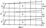
На фиг. 1 показана эпюра напряжений, получаемых в рельсовой плети при реализации прототипа (Рис. 4.1 отчета НИИЖТа по НИР, регистрационный номер N Б875401); на фиг. 2,а - эпюра напряжений в рельсовой плети при реализации предлагаемого технического решения; расчетные напряжения установлены на участке 0-1 рельсовой плети. На фиг. 2,б - то же; расчетные напряжения установлены на участке 0-2 рельсовой плети; на фиг. 2,в - то же; расчетные напряжения установлены на участке 0-3 рельсовой плети. In FIG. 1 shows a plot of the stresses obtained in a rail lash during the implementation of the prototype (Fig. 4.1 report NIIZhT research, registration number N Б875401); in FIG. 2, a - diagram of stresses in the rail lash during the implementation of the proposed technical solution; rated voltages are installed in the area 0-1 rail lashes. In FIG. 2, b - the same; rated voltages are installed on the 0-2 rail lash section; in FIG. 2, c - the same; rated voltages are installed in the 0-3 rail lash section.
Предлагаемый способ укладки рельсовых плетей бесстыкового пути реализуется следующим образом. The proposed method of laying rail lashes of the welded jointless path is implemented as follows.
Требуется уложить, например, рельсовую плеть бесстыкового пути из рельсов типа P - 65 длиной 700 м (L = 700 м). Принятая расчетная температура закрепления рельсовой плети бесстыкового пути равна, например, 20oC (tp)= 20oC)). Фактическая температура рельсов в момент укладки равна, например, -10oC (t = -10oC). Площадь поперечного сечения рельса типа P - 65 равна 82,6 см2 (F = 82,6). Погонное сопротивление перемещению рельсовой плети, вывешенной на ролики, равно 0,07 кН/м (P = 0,07 кН/м). Контроль за получением требуемых значений напряжений осуществляют, например, по перемещению контрольных сечений рельсовой плети (1,2,...,6) относительно маячных шпал и расположенных на расстоянии lo = 100 м друг от друга.It is required to lay, for example, a rail whip of a weld-free path of rails of type P - 65 with a length of 700 m (L = 700 m). The accepted design temperature for securing the rail whip of the welded jointless path is, for example, 20 ° C (t p ) = 20 ° C)). The actual temperature of the rails at the time of installation is, for example, -10 o C (t = -10 o C). The cross-sectional area of a P-65 rail is 82.6 cm 2 (F = 82.6). The linear resistance to movement of the rail lash hung on the rollers is 0.07 kN / m (P = 0.07 kN / m). Monitoring to obtain the required voltage values is carried out, for example, by moving the control sections of the rail lash (1,2, ..., 6) relative to the lighthouse sleepers and located at a distance of l o = 100 m from each other.
Для получения требуемых значений напряжений на участке от начала рельсовой плети до контрольного сечения N 1 необходимо приложить к другому концу рельсовой плети продольную растягивающую силу величиной

Для получения требуемых значений напряжений на участки 1-2 рельсовой плети продольную силу необходимо уменьшить на величину, определяемую по формуле ΔN1-2= q•l1-2 и довести до следующего значения N1-2:
N1-2= N+ΔN-ΔN1-2=656,05 кН-0,07•100=649,05 кН. .To obtain the required stress values in the area from the beginning of the rail lash to the control section N 1, it is necessary to apply a longitudinal tensile force to the other end of the rail lash of
To obtain the required voltage values for sections 1-2 of the rail lash, the longitudinal force must be reduced by an amount determined by the formula ΔN 1-2 = q • l 1-2 and brought to the following value N 1-2 :
N 1-2 = N + ΔN-ΔN 1-2 = 656.05 kN-0.07 • 100 = 649.05 kN. .
Для получения требуемых значений напряжений на участке 2-3 рельсовой плети продольную силу дополнительно необходимо уменьшить на величину ΔN2-3= q•l2-3 и довести до следующего значения N2-3:
N2-3= N1-2-q•l2-3=649,05-0,07•100=642,05 кН.
и т. д. до полного ввода всей рельсовой плети в расчетный режим эксплуатации и закрепления ее на подрельсовом основании.To obtain the required stress values in the section 2-3 of the rail lash, the longitudinal force must be additionally reduced by ΔN 2-3 = q • l 2-3 and brought to the following value N 2-3 :
N 2-3 = N 1-2 -q • l 2-3 = 649.05-0.07 • 100 = 642.05 kN.
etc. until the entire rail lash is fully entered into the design mode of operation and secured to it on a rail base.
Последовательность выполнения отдельных операций при реализации предлагаемого способа следующая:
укладывают рельсовую плеть подошвой на ролики, устанавливаемые на подрельсовом основании;
жестко закрепляют один конец рельсовой плети;
прикладывают к другому концу рельсовой плети продольное растягивающее усилие величиной равной 656,05 кН;
удаляют ролики из-под подошвы рельса на участке от жестко закрепленного конца рельсовой плети до контрольного сечения N 1;
закрепляют рельсовую плеть на подрельсовом основании на участке от жестко закрепленного конца рельсовой плети до контрольного сечения N 1;
уменьшают величину продольного усилия до 649,05 кН;
удаляют, после установки контрольного сечения N 2 в проектное положение, ролики из-под подошвы рельса на участке между контрольными сечениями NN 1 и 2;
закрепляют рельсовую плеть на подрельсовом основании на участке между контрольными сечениями N 1 и N 2:
уменьшают величину продольного усилия до 642,05 кН;
удаляют, после установки контрольного сечения N 3 в проектное положение, ролики из-под подошвы рельса на участья между контрольными сечениями NN 2 и 3;
закрепляют рельсовую плеть на подрельсовом основании на участке между контрольными сечениями NN 2 и 3.The sequence of operations for the implementation of the proposed method is as follows:
stack the rail whip with the sole on the rollers mounted on the rail base;
rigidly fasten one end of the rail lash;
apply a longitudinal tensile force of 656.05 kN to the other end of the rail lash;
remove the rollers from under the sole of the rail in the area from the rigidly fixed end of the rail lash to the control section N 1;
fix the rail lash on the rail base in the area from the rigidly fixed end of the rail lash to the control section N 1;
reduce the longitudinal force to 649.05 kN;
remove, after installing the
fix the rail lash on the rail base in the area between the control sections N 1 and N 2:
reduce the longitudinal force to 642.05 kN;
remove, after installing the control section N 3 in the design position, the rollers from under the sole of the rail for participation between the
fix the rail lash on the rail base in the area between the
Далее операции повторяются до полного закрепления рельсовой плети. Next, the operations are repeated until the rail lash is fully fixed.
Предлагаемый способ укладки рельсовых плетей бесстыкового пути позволит повысить эффективность за счет получения по всей длине плети равномерных значений напряжений, соответствующих принятой расчетной температуре закрепления плетей на постоянный режим эксплуатации. The proposed method of laying rail lashes of the welded jointless path will increase efficiency by obtaining uniform voltage values along the entire length of the lash, corresponding to the accepted design temperature of lashing fastening for continuous operation.
Claims (1)
N + ΔN = a•E•F(tр-tу) + P(L-li),
где N - величина продольной силы, способная создать в рельсовой плети напряжения, соответствующие принятой расчетной температуре закрепления рельсовой плети;
ΔN - дополнительная величина продольной силы, устраняющая влияние погонного сопротивления перемещению рельсовой плети;
а - коэффициент линейного расширения рельсовой стали;
Е - модуль упругости рельсовой стали;
tр - принятая расчетная температура закрепления рельсовой плети на постоянный режим эксплуатации;
tу - температура рельса при его укладке;
Р - погонное сопротивление перемещению рельсовой плети;
L - длина укладываемой рельсовой плети;
F - площадь поперечного сечения рельса;
li - длина закрепленного участка рельсовой плети и участка с создаваемыми в нем напряжениями, соответствующими принятой расчетной температуре закрепления рельсовой плети на постоянный режим эксплуатации,
уменьшают величину продольной силы по мере получения на отдельных участках рельсовой плети в направлении от жестко закрепленного конца к другому ее концу необходимы значений напряжений, а затем закрепляют отдельные эти участки.The method of laying the rail whip of the weld jointless path, which consists in laying the rail whip with the sole on the roller mounted on the rail base, rigidly fix one end of it, apply longitudinal tensile force to the other end thereof, remove the rollers from under the sole of the rail whip and fix the rail to lash on a rail track, characterized in that a large amount of longitudinal force, calculated by the formula, is applied in the initial period of work
N + ΔN = a • E • F (t p -t y ) + P (Ll i ),
where N is the magnitude of the longitudinal force capable of creating stresses in the rail lash that correspond to the accepted design temperature for fixing the rail lash;
ΔN is an additional value of the longitudinal force, eliminating the influence of linear resistance to movement of the rail lash;
a is the coefficient of linear expansion of rail steel;
E - modulus of elasticity of rail steel;
t p - the accepted design temperature of the rail lash fastening for continuous operation;
t у - rail temperature during its laying;
P - linear resistance to movement of the rail lash;
L is the length of the stacked rail lash;
F is the cross-sectional area of the rail;
l i is the length of the fixed section of the rail lash and the section with the voltages created in it corresponding to the accepted design temperature of the rail lash fixing for continuous operation,
they reduce the longitudinal force as they obtain on individual sections of the rail lash in the direction from the rigidly fixed end to its other end, the required voltage values, and then these individual sections are fixed.
Priority Applications (1)
| Application Number | Priority Date | Filing Date | Title |
|---|---|---|---|
| RU97109504A RU2112103C1 (en) | 1997-06-04 | 1997-06-04 | Method of laying continuous welded rail lengths |
Applications Claiming Priority (1)
| Application Number | Priority Date | Filing Date | Title |
|---|---|---|---|
| RU97109504A RU2112103C1 (en) | 1997-06-04 | 1997-06-04 | Method of laying continuous welded rail lengths |
Publications (2)
| Publication Number | Publication Date |
|---|---|
| RU2112103C1 true RU2112103C1 (en) | 1998-05-27 |
| RU97109504A RU97109504A (en) | 1998-11-20 |
Family
ID=20193890
Family Applications (1)
| Application Number | Title | Priority Date | Filing Date |
|---|---|---|---|
| RU97109504A RU2112103C1 (en) | 1997-06-04 | 1997-06-04 | Method of laying continuous welded rail lengths |
Country Status (1)
| Country | Link |
|---|---|
| RU (1) | RU2112103C1 (en) |
Cited By (5)
| Publication number | Priority date | Publication date | Assignee | Title |
|---|---|---|---|---|
| RU2151833C1 (en) * | 1998-07-06 | 2000-06-27 | Закрытое акционерное общество Научно-производственный центр информационных и транспортных систем | Continuous welded rails laying method |
| RU2437978C2 (en) * | 2010-02-15 | 2011-12-27 | Государственное образовательное учреждение высшего профессионального образования "Самарский государственный университет путей сообщения" (СамГУПС) | Method to install continuous welded rail |
| ES2398992R1 (en) * | 2011-04-14 | 2013-08-26 | Administrador De Infraestructuras Ferroviarias Adif | GUIDING PARTS OF RAILWAY RAILWAYS WITHOUT CURVED JOINTS DURING LONGITUDINAL VOLTAGE RELEASE OPERATION IN THE RAIL. |
| RU2500850C1 (en) * | 2012-05-14 | 2013-12-10 | Федеральное государственное бюджетное образовательное учреждение высшего профессионального образования "Самарский государственный университет путей сообщения" (СамГУПС) | Method of laying continuous welded rail track sleeper-and-rail section |
| RU2521114C1 (en) * | 2012-12-27 | 2014-06-27 | Открытое акционерное общество "Объединенные электротехнические заводы" (ОАО "ЭЛТЕЗА") | Control method of rail strings of continuous welded railroad track |
-
1997
- 1997-06-04 RU RU97109504A patent/RU2112103C1/en active
Cited By (5)
| Publication number | Priority date | Publication date | Assignee | Title |
|---|---|---|---|---|
| RU2151833C1 (en) * | 1998-07-06 | 2000-06-27 | Закрытое акционерное общество Научно-производственный центр информационных и транспортных систем | Continuous welded rails laying method |
| RU2437978C2 (en) * | 2010-02-15 | 2011-12-27 | Государственное образовательное учреждение высшего профессионального образования "Самарский государственный университет путей сообщения" (СамГУПС) | Method to install continuous welded rail |
| ES2398992R1 (en) * | 2011-04-14 | 2013-08-26 | Administrador De Infraestructuras Ferroviarias Adif | GUIDING PARTS OF RAILWAY RAILWAYS WITHOUT CURVED JOINTS DURING LONGITUDINAL VOLTAGE RELEASE OPERATION IN THE RAIL. |
| RU2500850C1 (en) * | 2012-05-14 | 2013-12-10 | Федеральное государственное бюджетное образовательное учреждение высшего профессионального образования "Самарский государственный университет путей сообщения" (СамГУПС) | Method of laying continuous welded rail track sleeper-and-rail section |
| RU2521114C1 (en) * | 2012-12-27 | 2014-06-27 | Открытое акционерное общество "Объединенные электротехнические заводы" (ОАО "ЭЛТЕЗА") | Control method of rail strings of continuous welded railroad track |
Similar Documents
| Publication | Publication Date | Title |
|---|---|---|
| RU2468135C2 (en) | Rail joint with ability of transverse adjustment of rail position | |
| RU2112103C1 (en) | Method of laying continuous welded rail lengths | |
| RU2136800C1 (en) | Method and device for installing functional modules of tracked transportation facilities | |
| JP4824690B2 (en) | "Electric vehicle power supply device via floor" | |
| US5249654A (en) | Surface rail for composite continuous rail | |
| US4368845A (en) | Railroad crossing structure | |
| CN100489194C (en) | Travelling rail for magnetic suspension train | |
| RU97109504A (en) | METHOD FOR LAYING A SANDLESS RAIL RAILWAY | |
| US5899417A (en) | Device for securing stock rails in railway switches | |
| JP3546932B2 (en) | Track extension device for floating railway | |
| RU2112102C1 (en) | Method of laying continuous welded rail lengths | |
| RU2020455C1 (en) | Nonballast railway track and method of its fatigue testing | |
| PT905319E (en) | PROCESS FOR THE CONSTRUCTION OF A FIXED RAILWAY FOR RAILWAY TRAFFIC, AS WELL AS A FERRY ROAD FIXED FOR THE EXECUTION OF THE PROCESS | |
| HU218774B (en) | Track and procedure for track mounting | |
| DE60329315D1 (en) | Track superstructure | |
| RU2151833C1 (en) | Continuous welded rails laying method | |
| RU98112821A (en) | METHOD FOR LAYING A SANDLESS RAIL RAILWAY | |
| RU2280725C2 (en) | Fastening device to connect rail to sleepers | |
| KR100638382B1 (en) | Resetting method using extension joints of straight and curved poles | |
| RU2068469C1 (en) | Method of jointless track rail length laying in curvilinear railroad sections | |
| RU2472894C1 (en) | Method of removing thermal stress in continuous welded track rail-and-tie assembly | |
| RU2732635C1 (en) | Method for uninterrupted path strings laying with their extension, by welding and entering into optimal fixation temperature | |
| CN1836074B (en) | Equipment for conveying preassembled turnouts intended for fixed carriageways | |
| RU2041307C1 (en) | Method for placing rail/sleeper grid in curvilinear sections of a railway | |
| RU2228980C2 (en) | Anchor rail fastening |