RU2113103C1 - Threshing unit drum - Google Patents
Threshing unit drum Download PDFInfo
- Publication number
- RU2113103C1 RU2113103C1 RU96114927A RU96114927A RU2113103C1 RU 2113103 C1 RU2113103 C1 RU 2113103C1 RU 96114927 A RU96114927 A RU 96114927A RU 96114927 A RU96114927 A RU 96114927A RU 2113103 C1 RU2113103 C1 RU 2113103C1
- Authority
- RU
- Russia
- Prior art keywords
- spokes
- whips
- rings
- scourges
- section
- Prior art date
Links
- 241000607479 Yersinia pestis Species 0.000 claims description 5
- 238000006073 displacement reaction Methods 0.000 claims description 4
- 238000009940 knitting Methods 0.000 claims description 4
- 241000251169 Alopias vulpinus Species 0.000 claims description 2
- 230000000694 effects Effects 0.000 abstract description 2
- 239000000126 substance Substances 0.000 abstract 1
- 230000007423 decrease Effects 0.000 description 3
- 238000009825 accumulation Methods 0.000 description 1
- 230000015572 biosynthetic process Effects 0.000 description 1
- 235000008429 bread Nutrition 0.000 description 1
- 235000013339 cereals Nutrition 0.000 description 1
- 230000001934 delay Effects 0.000 description 1
Images


Landscapes
- Threshing Machine Elements (AREA)
Abstract
Description
Изобретение относится к сельскохозяйственному машиностроению, в частности, к молотильным устройствам для зерновых культур. The invention relates to agricultural machinery, in particular, to threshing devices for grain crops.
Известно молотильное устройство, содержащее деку, молотильный барабан с валом, на котором расположены с помощью дисков и подбичников бичи с рифами [1]. Known threshing device containing a deck, a threshing drum with a shaft on which are located with the help of discs and headers whips with reefs [1].
Недостатком указанной конструкции является низкое качество вымолота и низкая производительность. The disadvantage of this design is the low quality of the grinding and low productivity.
Известно молотильное устройство с вибрирующими бичами [2]. Молотильное устройство содержит деку и молотильный барабан с валом, на котором установлены фланцы. Во фланцах посредством соединения типа ласточкин хвост закреплены гибкие подбичники в виде прутков, между которыми установлены пружины, причем на концах подбичников установлены бичи. Known threshing device with vibrating scourges [2]. The threshing device comprises a deck and a threshing drum with a shaft on which flanges are mounted. In flanges, by means of a dovetail type connection, flexible headers in the form of rods are fixed, between which springs are installed, and whips are installed at the ends of the headers.
Недостатком этого молотильного устройства является отклонение отдельных бичей при перегрузке в сторону, что приводит к увеличению дебаланса. The disadvantage of this threshing device is the deviation of individual whips during overloading to the side, which leads to an increase in unbalance.
Наиболее близким к предлагаемому изобретению является молотильное устройство с вибрирующими бичами [3]. Closest to the proposed invention is a threshing device with vibrating scourges [3].
Барабан молотильного устройства выполнен двухсекционным и снабжен гибкими спицами, причем каждая из секций выполнена на всю ширину молотилки, имеет общие ступицы, а бичи одной секции соединены со ступицами через гибкие подбичники, чередуются с бичами второй секции. The threshing drum is made of two sections and equipped with flexible knitting needles, each section being made over the entire width of the thresher, has common hubs, and the whips of one section are connected to the hubs through flexible headers, alternating with the scourges of the second section.
Недостатком этого устройства является то, что оно не обеспечивает нужное качество обмолота, т.к., ударяя по стеблям, увлекают их к подбарабанью, которое благодаря поперечным планкам их задерживает, обгоняя слой стеблей, находящихся между барабаном и подбарабаньем, бичи проходят по нему и сдвигают его перед собой. При этом происходит движение стеблей, таким образом, каждый слой стеблей, расположенный выше, увлекает за собой силами трения, а слой стеблей, расположенный ниже, частично зацепляя за решетку подбарабанья, замедляет движение, происходит проскальзывание верхних стеблей по нижним, и скорость движения нижних стеблей уменьшается. Наиболее препятствует движению самый нижний слой, который движется по ребристой поверхности подбарабанья. Вследствие чего по мере накопления образуется слой стеблевой массы на поверхности подбарабанья и одновременно с уменьшением зазоров между бичом и декой снижается протирание и пропускная способность молотильного аппарата. The disadvantage of this device is that it does not provide the required quality of threshing, because, striking the stems, they carry them to the concave, which, thanks to the transverse bars, delays them, overtaking the layer of stems located between the drum and the concave, the scourges pass through it and move it in front of you. In this case, the stalks move, so each stalk layer located above carries away friction forces, and the stalk layer below, partially hooking the concave grating, slows down the movement of the upper stems along the lower ones, and the speed of the lower stems decreases. The lowest layer, which moves along the ribbed surface of the concave, is the most obstructing movement. As a result, as a result of accumulation, a layer of stem mass is formed on the concave surface and, simultaneously with a decrease in the gaps between the scourge and deck, the rubbing and throughput of the threshing apparatus decreases.
Целью изобретения является повышение производительности труда молотильного устройства и надежности в работе. The aim of the invention is to increase the productivity of the threshing device and reliability.
Поставленная цель достигается тем, что в предлагаемом устройстве, в отличие от прототипа, бичи молотильного устройства в первой секции по окружности и порядно, концы спиц каждого ряда соединены с одним концом, а бичи закреплены на концах с чередованием бичей одноименных колец, бичи которых смещаются по окружности; во второй секции бичи снабжены рядами зубьев размером 20 мм в шахматном порядке, которые выполнены у основания по логарифмической спирали, а бичи имеют прямоугольную форму сечения. This goal is achieved by the fact that in the proposed device, in contrast to the prototype, the scourges of the threshing device in the first section are circumferentially and in order, the ends of the spokes of each row are connected to one end, and the scourges are fixed at the ends with alternating scourges of the same rings, the scourges of which are shifted along Circumference in the second section, the scourges are equipped with rows of teeth measuring 20 mm in a checkerboard pattern, which are made at the base in a logarithmic spiral, and the scourges have a rectangular cross-sectional shape.
Следовательно, предлагаемое устройство соответствует критерию "новизна". Therefore, the proposed device meets the criterion of "novelty."
Сравнение предлагаемого устройства с другими известными источниками дает основание утверждать соответствие его критерию "изобретательский уровень". Comparison of the proposed device with other well-known sources gives reason to claim compliance with its criterion of "inventive step".
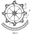
На фиг. 1 показан барабан в аксонометрии; на фиг. 2 - вид по стрелке А фиг. 1; на фиг. 3 - продольный разрез барабана; на фиг. 4 - узел на фиг. 2. In FIG. 1 shows a drum in a perspective view; in FIG. 2 is a view along arrow A of FIG. one; in FIG. 3 is a longitudinal section of a drum; in FIG. 4 - node in FIG. 2.
Барабан молотильного устройства 1 содержит вал 2 со ступицами 3, на которых по окружности закреплены гибкие спицы 4 в два ряда на каждой из ступиц 3 и со смещением одного ряда относительно другого вдоль оси вала 2 и со смещением по окружности каждой спицы 4 одного ряда относительно спиц 4 другого ряда на половину угла между спицами 4 одного и того же ряда, концы 5 спиц 4 каждого ряда соединены с кольцом 6 с возможностью радиального смещения концов 5 относительно кольца 6. На кольцах 6 размещены подбичники 7, на которых установлены на первой секции бичи 8 с наклонными рифами 9, которые противоположны по отношению к смежным бичам. The drum of the
Вторая секция барабана представляет собой бичи 12 с зубьями 13 типа штифтов, без рифов, которые связаны со спицами 4 посредством колец 6 и подбичников 7. Из спиц 4 одноименных из них колец 6, подбичников 7 и бичей 12 с зубьями 13 образованы две части с чередованием и возможностью относительного смещения по окружности бичей 12 с зубьями 13 другой секции. Спицы выполнены в виде плоских пластин, плоскости которые перпендикулярны плоскости вращения барабана. The second section of the drum is a
Крепление колец к спицам может быть осуществлено посредством, например, жестко установленных на кольцах 6 уголков 9, болтовых соединений 10 и паза 11 в уголке 9. The fastening of the rings to the spokes can be carried out by means of, for example,
Зубья барабана размещены на остове 7 подбичника по винтовой линии или в шахматном порядке так, что соединение следов зубьев частично перекрывают друг друга, а вершины всех зубьев лежат на одной цилиндрической поверхности. Зубья имеют высоту 20 мм. The teeth of the drum are placed on the skeleton 7 of the head unit along a helical line or in a checkerboard pattern so that the connection of the tooth traces partially overlap each other, and the tops of all the teeth lie on one cylindrical surface. The teeth are 20 mm high.
Барабан молотильного устройства работает следующим образом. The drum threshing device operates as follows.
При вращении барабана 1 молотильного устройства бичи 8 попеременно и последовательно проходят мимо планок деки в условиях переменной, непостоянной по величине подачи массы, что вызывает удары бичей на хлебную массу, вызывающую относительное смещение бичей 8 и 12 с зубьями, повышающее эффект обмолота и разрушающее образование слоя на поверхности деки. When the
Источники информации:
1. Е.С.Босого. Теория, конструкция и расчет сельскохозяйственных машин, 1973, с. 331-332.Sources of information:
1. E.S. Bosogo. Theory, design and calculation of agricultural machinery, 1973, p. 331-332.
2. Авторское свидетельство СССР N 1301348, кл. A 01 F 12/18, 1980. 2. Copyright certificate of the USSR N 1301348, cl. A 01 F 12/18, 1980.
3. Авторское свидетельство СССР N 1554814, кл. A 01 F 12/20, 1989. 3. USSR author's certificate N 1554814, cl. A 01 F 12/20, 1989.
Claims (1)
Priority Applications (1)
| Application Number | Priority Date | Filing Date | Title |
|---|---|---|---|
| RU96114927A RU2113103C1 (en) | 1996-07-23 | 1996-07-23 | Threshing unit drum |
Applications Claiming Priority (1)
| Application Number | Priority Date | Filing Date | Title |
|---|---|---|---|
| RU96114927A RU2113103C1 (en) | 1996-07-23 | 1996-07-23 | Threshing unit drum |
Publications (2)
| Publication Number | Publication Date |
|---|---|
| RU2113103C1 true RU2113103C1 (en) | 1998-06-20 |
| RU96114927A RU96114927A (en) | 1998-10-10 |
Family
ID=20183733
Family Applications (1)
| Application Number | Title | Priority Date | Filing Date |
|---|---|---|---|
| RU96114927A RU2113103C1 (en) | 1996-07-23 | 1996-07-23 | Threshing unit drum |
Country Status (1)
| Country | Link |
|---|---|
| RU (1) | RU2113103C1 (en) |
Cited By (5)
| Publication number | Priority date | Publication date | Assignee | Title |
|---|---|---|---|---|
| RU2197814C1 (en) * | 2001-06-21 | 2003-02-10 | Шевель Михаил Федорович | Threshing unit |
| RU2261581C2 (en) * | 2003-12-15 | 2005-10-10 | Чурсин Николай Ильич | Roll-free drum |
| RU192453U1 (en) * | 2019-04-16 | 2019-09-17 | Общество с ограниченной ответственностью "Комбайновый завод "Ростсельмаш" | PIN DRUM |
| RU194321U1 (en) * | 2019-10-16 | 2019-12-05 | Федеральное государственное бюджетное научное учреждение "Федеральный научный агроинженерный центр ВИМ" (ФГБНУ ФНАЦ ВИМ) | Threshing drum |
| RU200110U1 (en) * | 2020-06-16 | 2020-10-07 | Общество с ограниченной ответственностью "Комбайновый завод "Ростсельмаш" | PIN TYPE THRESHING DEVICE |
Citations (1)
| Publication number | Priority date | Publication date | Assignee | Title |
|---|---|---|---|---|
| SU1301348A1 (en) * | 1985-06-21 | 1987-04-07 | Красноярский сельскохозяйственный институт | Thrashing device |
-
1996
- 1996-07-23 RU RU96114927A patent/RU2113103C1/en active
Patent Citations (1)
| Publication number | Priority date | Publication date | Assignee | Title |
|---|---|---|---|---|
| SU1301348A1 (en) * | 1985-06-21 | 1987-04-07 | Красноярский сельскохозяйственный институт | Thrashing device |
Non-Patent Citations (1)
| Title |
|---|
| SU, авторск ое свидетельство, 1554814, кл. A 01 F 12/20, 1990. * |
Cited By (5)
| Publication number | Priority date | Publication date | Assignee | Title |
|---|---|---|---|---|
| RU2197814C1 (en) * | 2001-06-21 | 2003-02-10 | Шевель Михаил Федорович | Threshing unit |
| RU2261581C2 (en) * | 2003-12-15 | 2005-10-10 | Чурсин Николай Ильич | Roll-free drum |
| RU192453U1 (en) * | 2019-04-16 | 2019-09-17 | Общество с ограниченной ответственностью "Комбайновый завод "Ростсельмаш" | PIN DRUM |
| RU194321U1 (en) * | 2019-10-16 | 2019-12-05 | Федеральное государственное бюджетное научное учреждение "Федеральный научный агроинженерный центр ВИМ" (ФГБНУ ФНАЦ ВИМ) | Threshing drum |
| RU200110U1 (en) * | 2020-06-16 | 2020-10-07 | Общество с ограниченной ответственностью "Комбайновый завод "Ростсельмаш" | PIN TYPE THRESHING DEVICE |
Similar Documents
| Publication | Publication Date | Title |
|---|---|---|
| RU2113103C1 (en) | Threshing unit drum | |
| JP2020151846A (en) | Blade assembly for food cutting | |
| NL8400884A (en) | HEAD FOR A CABIN REMOVAL MACHINE. | |
| RU2238630C2 (en) | Threshing apparatus | |
| RU96114927A (en) | THRESHING DRUM DRUM | |
| EP1207971B1 (en) | Separating device | |
| RU2205532C2 (en) | Threshing unit | |
| RU2157610C1 (en) | Rotor for licorice root extracting machine | |
| SU1271439A1 (en) | Thrashing device | |
| SU1395180A1 (en) | Feeler roller for root and tuber harvesting machine | |
| RU2242101C1 (en) | Soil tillage roller | |
| RU2308825C1 (en) | Drum of threshing apparatus | |
| RU189812U1 (en) | CHILDREN'S DRUM | |
| SU1554814A1 (en) | Threshing drum | |
| US2320945A (en) | Thresher cylinder construction | |
| US724855A (en) | Harvester threshing-machine. | |
| RU202400U1 (en) | DRUM FOR THRESHING DEVICE OF GRAIN HARVESTOR | |
| SU694110A1 (en) | Self -cleaning harrow | |
| SU1496698A1 (en) | Thrashing and separating device | |
| RU2770478C1 (en) | Working body for tillage | |
| RU2415552C1 (en) | Feeder of combine harvester thresher | |
| RU2377761C1 (en) | Thresher device | |
| JP7766676B2 (en) | Food processing device, food processing method, and food manufacturing method | |
| SU400274A1 (en) | ||
| SU1304772A1 (en) | Rotary separator |