RU2136830C1 - Power transmission line support - Google Patents
Power transmission line support Download PDFInfo
- Publication number
- RU2136830C1 RU2136830C1 SU5016122A RU2136830C1 RU 2136830 C1 RU2136830 C1 RU 2136830C1 SU 5016122 A SU5016122 A SU 5016122A RU 2136830 C1 RU2136830 C1 RU 2136830C1
- Authority
- RU
- Russia
- Prior art keywords
- mast
- shell
- beams
- flanges
- spherical surface
- Prior art date
Links
- 230000005540 biological transmission Effects 0.000 title abstract description 10
- 239000002131 composite material Substances 0.000 claims abstract description 10
- 239000012765 fibrous filler Substances 0.000 claims description 3
- 230000015572 biosynthetic process Effects 0.000 claims 1
- 239000011230 binding agent Substances 0.000 abstract description 8
- 238000004804 winding Methods 0.000 abstract description 5
- 238000010276 construction Methods 0.000 abstract description 3
- 238000004519 manufacturing process Methods 0.000 abstract description 3
- 230000000694 effects Effects 0.000 abstract description 2
- 239000000126 substance Substances 0.000 abstract description 2
- 239000002657 fibrous material Substances 0.000 abstract 1
- 239000000945 filler Substances 0.000 description 6
- 239000000463 material Substances 0.000 description 5
- 238000005452 bending Methods 0.000 description 4
- 239000011152 fibreglass Substances 0.000 description 4
- 239000000835 fiber Substances 0.000 description 3
- 238000005260 corrosion Methods 0.000 description 2
- 230000007797 corrosion Effects 0.000 description 2
- 239000011521 glass Substances 0.000 description 2
- 239000003292 glue Substances 0.000 description 2
- 239000004033 plastic Substances 0.000 description 2
- 229920000642 polymer Polymers 0.000 description 2
- 239000011150 reinforced concrete Substances 0.000 description 2
- 230000007704 transition Effects 0.000 description 2
- 229920000049 Carbon (fiber) Polymers 0.000 description 1
- 206010040925 Skin striae Diseases 0.000 description 1
- 208000031439 Striae Distensae Diseases 0.000 description 1
- 150000001720 carbohydrates Chemical class 0.000 description 1
- 239000004917 carbon fiber Substances 0.000 description 1
- 239000012634 fragment Substances 0.000 description 1
- 238000010438 heat treatment Methods 0.000 description 1
- 230000036039 immunity Effects 0.000 description 1
- 239000011159 matrix material Substances 0.000 description 1
- 229910052751 metal Inorganic materials 0.000 description 1
- 239000002184 metal Substances 0.000 description 1
- 150000002739 metals Chemical class 0.000 description 1
- VNWKTOKETHGBQD-UHFFFAOYSA-N methane Chemical compound C VNWKTOKETHGBQD-UHFFFAOYSA-N 0.000 description 1
- 238000000034 method Methods 0.000 description 1
- 238000012986 modification Methods 0.000 description 1
- 230000004048 modification Effects 0.000 description 1
- 238000003032 molecular docking Methods 0.000 description 1
- 230000008520 organization Effects 0.000 description 1
- -1 organoplastics Substances 0.000 description 1
- 239000002994 raw material Substances 0.000 description 1
- 239000012763 reinforcing filler Substances 0.000 description 1
- 239000002689 soil Substances 0.000 description 1
- 239000007787 solid Substances 0.000 description 1
- 125000006850 spacer group Chemical group 0.000 description 1
- 229920003002 synthetic resin Polymers 0.000 description 1
- 239000000057 synthetic resin Substances 0.000 description 1
Images


Landscapes
- Rod-Shaped Construction Members (AREA)
Abstract
Description
Изобретение относится к строительству, а именно к сооружению линий электропередач и связи. The invention relates to the construction, namely the construction of power lines and communications.
Известна опора, образованная пластиковым корпусом, армированная вертикальными и охватывающими их спиральными элементами, выполненными в виде жгутов из "пластмассы", армированной стекловолокном (см. патент СССР N 784804, Мкл. E 04 H 12/00, публ. 1980 г.). Known support, formed by a plastic casing, reinforced with vertical and enveloping spiral elements made in the form of bundles of "plastic" reinforced with fiberglass (see USSR patent N 784804, Mcl. E 04
Недостатком известной опоры является большая материалоемкость и пониженная прочность при работе на изгиб. A disadvantage of the known support is a large material consumption and reduced strength during bending.
Наиболее близкой к заявленной является опора линий электропередач, содержащая мачту, образованную расположенными вдоль образующих тела вращения наклонными скрещивающимися прямолинейными стойками, и траверсу для монтажа проводов (см. авторское свидетельство СССР N 969869, Мкл. E 04 H 12/00, 82). Closest to the claimed one is a power line support containing a mast formed by inclined straight rectilinear racks located along the bodies of rotation and a crosshead for mounting wires (see USSR author's certificate N 969869, Mcl. E 04
Недостатком известной опоры является большая масса, так как стойки выполнены из железобетона, низкая технологичность изготовления и прочность. Кроме того, траверса выполнена заодно целое со стойками, поэтому ее элементы работают на изгиб, что приводит к необходимости увеличивать массу для обеспечения требуемой жесткости. A disadvantage of the known support is a large mass, since the racks are made of reinforced concrete, low manufacturability and strength. In addition, the traverse is made integral with the uprights, so its elements work in bending, which leads to the need to increase the mass to provide the required stiffness.
Целью изобретения является снижение массы и повышение технологичности. The aim of the invention is to reduce weight and improve manufacturability.
Сущность изобретения заключается в том, что в опоре линии электропередач, содержащей мачту, образованную расположенными по замкнутой поверхности скрещивающимися элементами, и связанную с ней соединительным узлом траверсу для установки проводов, согласно изобретению, скрещивающиеся элементы образованы лентой из композиционного материала, включающей в себя волокнистый наполнитель и связующий компонент, причем в местах скрещивания лента соединена связующим компонентом. The essence of the invention lies in the fact that in the support of a power line containing a mast formed by crossing elements located on a closed surface and a connecting beam for connecting wires according to the invention, the crossing elements are formed by a tape of a composite material including a fibrous filler and a binder component, and in the places of crossing the tape is connected by a binder component.
Изобретение отличается также тем, что мачта образована по высоте соединенными между собой, секциями, каждая из которых включает в себя каркас и два фланца с пазами на наружной поверхности, в которых расположены петли указанной ленты, соединяющие указанные скрещивающиеся элементы. The invention is also characterized in that the mast is formed in height by interconnected sections, each of which includes a frame and two flanges with grooves on the outer surface, in which loops of the specified tape are located connecting these crossing elements.
Изобретение отличается также тем, что соединительный узел образован соединенным с фланцами переходником, с по меньшей мере двумя шарнирными узлами, каждый из которых включает в себя закрепленную в корпусе переходника обечайку с внутренней сферической поверхностью, в которой установлено с возможностью поворота кольцо с наружной сферической поверхностью, на которой выполнены пазы для укладки ленты из композиционного материала, которой образована траверса, выполненная в виде сетчатой оболочки. The invention is also characterized in that the connecting unit is formed by an adapter connected to the flanges, with at least two hinged nodes, each of which includes a ring with an internal spherical surface mounted in the adapter housing, in which a ring with an external spherical surface is mounted to rotate, on which grooves are made for laying a tape of composite material, which forms a traverse, made in the form of a mesh shell.
Кроме того, траверса образована по меньшей мере двумя связанными с фланцами секции мачты балками в виде сетчатой оболочки, свободными концами связанными с дополнительными балками для образования многогранника. In addition, the traverse is formed by at least two beams in the form of a mesh shell connected with the flanges of the mast section, with free ends connected with additional beams to form a polyhedron.
Траверса в соответствии с изобретением может быть образована соединенными одними концами с фланцами одной из секций мачты балками, другие концы которых попарно связаны между собой и с кольцом жесткости, при этом кольцо жесткости может быть соединено растяжками с грунтом. The traverse in accordance with the invention can be formed by beams connected at one end to the flanges of one of the mast sections, the other ends of which are paired with each other and with the stiffening ring, while the stiffening ring can be connected by braces to the ground.
Изобретение проиллюстрировано на чертежах, где:
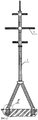
на фиг. 1 изображена опора линии электропередач (ЛЭП) на оттяжках;
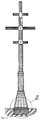
на фиг. 2 - изображена опора ЛЭП на подножниках;
на фиг. 3 - опора ЛЭП с увеличенным диаметром нижней секции;
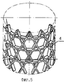
на фиг. 4 - фрагмент секции опоры в виде сетчатой оболочки с вертикальными и кольцевыми скрещивающимися элементами;
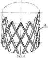
на фиг. 5 - то же, с сетчатой оболочкой с наклонными и кольцевыми скрещивающимися элементами;
на фиг. 6 - то же, с сетчатой оболочкой с наклонными скрещивающимися элементами;
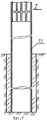
на фиг. 7 - место I на фиг. 1;
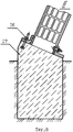
на фиг. 8 - место II на фиг. 2;
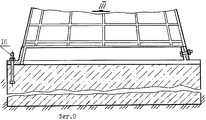
на фиг. 9 - место III на фиг. 3;
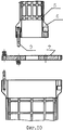
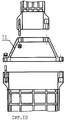
на фиг. 10 - изображено место соединения секций опоры посредством переходного кольца;
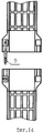
на фиг. 11 - то же, с несколькими переходными кольцами;
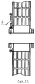
на фиг. 12 - место соединения двух фланцев секции посредством переходного фланца;
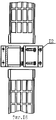
на фиг. 13 - место соединения секций опоры посредством конического переходного фланца;
на фиг. 14 - вариант соединения фланцев секций штифто-шпилечным соединением;
на фиг. 15 - то же, болтовым соединением;
на фиг. 16 - соединения секций посредством хомута;
на фиг. 17 - соединение секций посредством дополнительных фланцев;
на фиг. 18 - соединение секций посредством внутренней втулки;
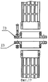
на фиг. 19 - крепление траверсы к опоре при помощи двух хомутов;
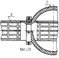
на фиг. 20 - крепление траверсы к внутренней перемычке опоры;
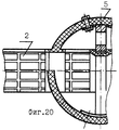
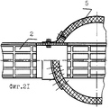
на фиг. 21 - крепление траверсы к наружной части опоры при помощи двух накладок;
на фиг. 22 - крепление траверсы при помощи клея;
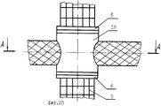
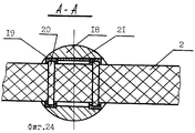
на фиг. 23 - крепление траверсы посредством переходника;
на фиг. 24 - сечение А-А на фиг. 23;
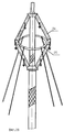
на фиг. 25 - опора ЛЭП с траверсой повышенной жесткости;
на фиг. 26 - опора ЛЭП с траверсой повышенной жесткости на оттяжках;
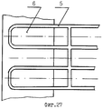
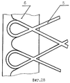
на фиг. 27 - соединение фланца с сетчатой оболочкой с вертикальными и кольцевыми скрещивающимися элементами;
на фиг. 28 - то же с наклонными элементами.The invention is illustrated in the drawings, where:
in FIG. 1 shows a transmission line support (power transmission line) on guy wires;
in FIG. 2 - shows the support of power lines on the footboards;
in FIG. 3 - transmission line support with an increased diameter of the lower section;
in FIG. 4 is a fragment of a support section in the form of a mesh shell with vertical and annular crossing elements;
in FIG. 5 - the same, with a mesh shell with inclined and annular crossing elements;
in FIG. 6 - the same, with a mesh shell with inclined crossing elements;
in FIG. 7 - place I in FIG. 1;
in FIG. 8 - place II in FIG. 2;
in FIG. 9 — place III in FIG. 3;
in FIG. 10 - shows the junction of the support sections by means of a transition ring;
in FIG. 11 - the same, with several adapter rings;
in FIG. 12 - the place of connection of the two flanges of the section through the adapter flange;
in FIG. 13 - the junction of the support sections by means of a conical transitional flange;
in FIG. 14 - an option for connecting the flanges of the sections with a pin-hairpin connection;
in FIG. 15 - the same, bolted;
in FIG. 16 - connection sections through a clamp;
in FIG. 17 - connection sections through additional flanges;
in FIG. 18 - connection of sections by means of an inner sleeve;
in FIG. 19 - fastening the traverse to the support using two clamps;
in FIG. 20 - fastening of the traverse to the internal jumper of the support;
in FIG. 21 - fastening the traverse to the outer part of the support using two pads;
in FIG. 22 - securing the beam with glue;
in FIG. 23 - securing the crosshead with an adapter;
in FIG. 24 is a section AA in FIG. 23;
in FIG. 25 - transmission line support with a traverse of increased rigidity;
in FIG. 26 - transmission line support with a traverse of increased rigidity on guy wires;
in FIG. 27 - connection of the flange with the mesh shell with vertical and annular crossing elements;
in FIG. 28 - the same with inclined elements.
Опора ЛЭП содержит мачту 1 и траверсу 2, связанные между собой соединительным узлом 3. Мачта 1 опоры и траверса 2 могут быть выполнены из намотанного композиционного материала, который обеспечивает высокую удельную прочность (в 2-5 раз выше, чем у металлов), высокую коррозионную стойкость в агрессивных средах и условиях всеклиматики, высокую технологичность конструкции, умеренную стоимость при серийном производстве, теоретически неограниченную сырьевую базу (применительно к стеклонаполнителям). The power transmission line support contains a mast 1 and a
Первый фактор обусловлен спецификой структурной организации такого материала, при которой основную нагрузку воспринимает высокопрочный волокнистый наполнитель (например, в виде нитей, жгутов, ровницы), ориентированный в объеме по направлению действия максимальных напряжений. Оптимально выбирая направления укладки наполнителя, можно в широком диапазоне управлять прочностными и жесткостными параметрами создаваемой конструкции и, следовательно, ее массой и материалоемкостью. The first factor is due to the specific structural organization of such a material, in which the main load is perceived by a high-strength fibrous filler (for example, in the form of threads, bundles, rovings), oriented in volume in the direction of maximum stresses. By optimally choosing the directions of filling the filler, it is possible to control in a wide range the strength and stiffness parameters of the structure being created and, consequently, its mass and material consumption.
Высокая коррозионная стойкость конструкции связана с невосприимчивостью компонентов материала к воздействию агрессивной среды. The high corrosion resistance of the structure is associated with the immunity of the components of the material to the effects of an aggressive environment.
Изготовление конструкции в большинстве случаев происходит за одну технологическую операцию. Fabrication of the structure in most cases occurs in one technological operation.
На практике наибольшее применение получили три вида КМ: стеклопластики, органопластики и углепластики. Соответственно для этих материалов армирующими наполнителями являются стеклянные, полимерные и углеводные волокна, различающиеся по своим свойствам по уровню физико-механических, электрических, химических и других характеристик. In practice, the three types of CMs are most widely used: fiberglass, organoplastics, and carbon fiber. Accordingly, for these materials, reinforcing fillers are glass, polymer and carbohydrate fibers, which differ in their properties in terms of physical, mechanical, electrical, chemical and other characteristics.
Полимерное связующее для этих волокон может быть одним и тем же или различаться некоторой модификацией с целью обеспечения высокой связи с волокном и увеличения термостойкости. The polymeric binder for these fibers can be the same or be different in some modifications in order to provide high bonding with the fiber and increase heat resistance.
Намоточный стеклопластик может быть, например, на основе стеклоткани (ТСУ8-3-ВМ-78) и связующего ЭХД-У или на основе ровинга РВМН10-1260-80 и связующего ЭХД-МК. Winding fiberglass can be, for example, based on fiberglass (TSU8-3-VM-78) and a binder ЭХД-У or based on the roving РВМН10-1260-80 and a binder ЭХД-МК.
Мачта и траверса выполняются в виде оболочки вращения методом намотки или укладки в пазы вращающейся оправки предварительно пропитанного или пропитываемого в процессе намотки наполнителя. В качестве связующего используют различные синтетические смолы, которые при последующей термической обработке становятся жесткой матрицей для наполнителя. Наполнителем и связующим образована многослойная лента, из которой выполнена сетчатая оболочка со скрещивающимися элементами 4. Могут быть получены различные варианты сетчатых оболочек: с расположением скрещивающихся элементов вертикально, по дуге окружности и наклонно (фиг. 4-6), причем в месте скрещивания соединение осуществляется за счет наполнителя. The mast and traverse are made in the form of a shell of rotation by winding or laying in the slots of a rotating mandrel pre-impregnated or impregnated in the process of winding the filler. As a binder, various synthetic resins are used, which, upon subsequent heat treatment, become a rigid matrix for the filler. A filler and a binder are formed of a multilayer tape, from which a mesh shell is made with
Каждая из перечисленных структур или схем обладает определенными эксплуатационными, экономическими, прочностными и жесткостными характеристиками. Например, оболочка, выполненная по схеме фиг. 4 обладает высокой жесткостью на изгиб, но имеет меньшую крутильную жесткость, по схеме фиг. 6 хорошее сопротивление кручению, но имеет меньшую изгибную жесткость, по схеме фиг. 5 обладает высокой и крутильной и изгибной четкостью. Each of the listed structures or schemes has certain operational, economic, strength and stiffness characteristics. For example, a shell made in accordance with the circuit of FIG. 4 has high bending stiffness, but has lower torsional stiffness, as shown in FIG. 6 has good torsion resistance, but has lower flexural rigidity, as shown in FIG. 5 has high torsional and flexural clarity.
Мачта может быть выполнена по высоте из отдельных секций, каждая из которых включает в себя сетчатый каркас 5 из композиционного материала и два фланца 6 для соединения с фланцем другой секции. The mast can be made in height from separate sections, each of which includes a
Фланцы выполнены с пазами на наружной поверхности, в которых расположены витки ленты для закрепления фланца к каркасу. В зависимости от структуры намотки пазы выполняются наклонными или прямыми, а витки ленты охватывают выступы между пазами, причем каждым витком охвачен соответствующий выступ. Фланцы секций могут соединяться посредством переходного кольца 7 болтовым соединением, шпилечным соединением 9 или болтовым соединением через переходный фланец 10, а также штифто-шпилечным соединением через конический переходный фланец 11. The flanges are made with grooves on the outer surface, in which the turns of the tape are located to fix the flange to the frame. Depending on the structure of the winding, the grooves are inclined or straight, and the turns of the tape cover the protrusions between the grooves, with each turn covering a corresponding protrusion. The flanges of the sections can be connected by means of a
Секции одного диаметра могут стыковаться посредством болтового 8 или штифто-шлилечного соединения 9, а также хомутами 12, дополнительными фланцами 13 или внутренней втулкой 14. Sections of the same diameter can be joined by means of a bolted 8 or pin-splined
Применение в конструкциях опор полимерных композиционных материалов практически не сказывается на особенностях крепления опоры: могут быть использованы углубления в пробуренную скважину с последующей засыпкой, в этом случае предполагается использовать сплошную обечайку 15 с целью исключения смятия грунта или крепление секций опор через анкерные болты 16 и фланцевое соединение с железобетонными подушками 17. The use of polymer composite materials in the structures of supports does not practically affect the features of support mounting: recesses into a drilled well can be used, followed by backfill, in this case it is proposed to use a continuous shell 15 to prevent crushing of the soil or fixing sections of supports through
Большую сложность представляет собой задача крепления траверс. Возможно крепление траверсы к мачте, как это представлено на фиг. 19-21. Например, в местах соединения с мачтой участки траверсы выполнены сплошными с кольцевой канавкой, в которой расположены хомуты (фиг. 19), причем этот участок может быть расположен в середине траверсы для соединения с внутренней перемычкой опоры (фиг. 20). Сплошные участки могут быть соединены с мачтой с помощью накладок или на клею (фиг. 21, 22). Of great difficulty is the task of securing the traverse. It is possible to attach the yoke to the mast, as shown in FIG. 19-21. For example, at the junction points with the mast, the sections of the traverse are made continuous with an annular groove in which the clamps are located (Fig. 19), and this section can be located in the middle of the traverse for connection with the internal bridge of the support (Fig. 20). Solid sections can be connected to the mast using pads or on glue (Fig. 21, 22).
Наиболее предпочтительным является вариант крепления траверс с двумя сферическими опорами, который исключает изгибающие нагрузки на траверсу, создавая только растягивающие и сжимающие нагрузки. В соответствии с этим вариантом фланцы 6 секций мачты соединяются с переходником, в корпусе 18 которого закреплены обечайки 19 с внутренней сферической поверхностью, в каждой из которых установлено с возможностью поворота кольцо 20 с наружной сферической поверхностью, на которой выполнены пазы для укладки ленты траверсы, что обеспечивает жесткое соединение кольца 20 с траверсой, между обечайками 19 может быть расположена распорная втулка 21. Most preferred is the mounting bracket with two spherical supports, which eliminates bending loads on the beam, creating only tensile and compressive loads. In accordance with this embodiment, the flanges of the 6 mast sections are connected to an adapter, in the
Для повышения жесткости траверсы она может быть выполнена из связанных с балкой 22 траверсы дополнительных балок 23, которые связаны одними концами между собой, например, посредством стыковочного узла 24, и с фланцами секций мачты, образуя многогранники различной формы. To increase the rigidity of the beam, it can be made of
Траверса может быть выполнена в виде балок 24, соединенных попарно с фланцами секции, между собой и с кольцом 25, которое может быть связано растяжками с грунтом. The traverse can be made in the form of
Claims (5)
Priority Applications (1)
| Application Number | Priority Date | Filing Date | Title |
|---|---|---|---|
| SU5016122 RU2136830C1 (en) | 1991-12-11 | 1991-12-11 | Power transmission line support |
Applications Claiming Priority (1)
| Application Number | Priority Date | Filing Date | Title |
|---|---|---|---|
| SU5016122 RU2136830C1 (en) | 1991-12-11 | 1991-12-11 | Power transmission line support |
Publications (1)
| Publication Number | Publication Date |
|---|---|
| RU2136830C1 true RU2136830C1 (en) | 1999-09-10 |
Family
ID=21591336
Family Applications (1)
| Application Number | Title | Priority Date | Filing Date |
|---|---|---|---|
| SU5016122 RU2136830C1 (en) | 1991-12-11 | 1991-12-11 | Power transmission line support |
Country Status (1)
| Country | Link |
|---|---|
| RU (1) | RU2136830C1 (en) |
Cited By (6)
| Publication number | Priority date | Publication date | Assignee | Title |
|---|---|---|---|---|
| MD3981C2 (en) * | 2009-02-16 | 2010-09-30 | Григоре ЧАПА | Anchor device for guy rods (variants) |
| CN102071822A (en) * | 2010-12-24 | 2011-05-25 | 广东省电力设计研究院 | Direct current filter structure for converter station |
| MD431Z (en) * | 2011-03-24 | 2012-05-31 | Григоре ЧАПА | Anchorage device |
| WO2013176582A1 (en) * | 2012-05-21 | 2013-11-28 | Бреветти Копирайт Лтд | Electrical transmission line support |
| US9416555B2 (en) | 2007-02-28 | 2016-08-16 | Seccional Brasil SA | Structure for supporting electric power transmission lines |
| RU2613231C1 (en) * | 2016-01-12 | 2017-03-15 | Общество с ограниченной ответственностью "ЭЛЕКТРОМАШ" | High strength support |
-
1991
- 1991-12-11 RU SU5016122 patent/RU2136830C1/en active
Non-Patent Citations (1)
| Title |
|---|
| Цыплаков О.Г. Конструирование изделий из композиционно-волокнистых материалов. - Л., 1984, с. 5-15. * |
Cited By (6)
| Publication number | Priority date | Publication date | Assignee | Title |
|---|---|---|---|---|
| US9416555B2 (en) | 2007-02-28 | 2016-08-16 | Seccional Brasil SA | Structure for supporting electric power transmission lines |
| MD3981C2 (en) * | 2009-02-16 | 2010-09-30 | Григоре ЧАПА | Anchor device for guy rods (variants) |
| CN102071822A (en) * | 2010-12-24 | 2011-05-25 | 广东省电力设计研究院 | Direct current filter structure for converter station |
| MD431Z (en) * | 2011-03-24 | 2012-05-31 | Григоре ЧАПА | Anchorage device |
| WO2013176582A1 (en) * | 2012-05-21 | 2013-11-28 | Бреветти Копирайт Лтд | Electrical transmission line support |
| RU2613231C1 (en) * | 2016-01-12 | 2017-03-15 | Общество с ограниченной ответственностью "ЭЛЕКТРОМАШ" | High strength support |
Similar Documents
| Publication | Publication Date | Title |
|---|---|---|
| US6878323B2 (en) | Method of manufacturing a stay-in-place form | |
| US4177306A (en) | Laminated sectional girder of fiber-reinforced materials | |
| CN104769280B (en) | wind turbine tower | |
| US7253786B1 (en) | Reinforced monopole construction | |
| CN101263270B (en) | Reinforcements made of fiber-reinforced plastic | |
| JP2007533883A5 (en) | ||
| RU2136830C1 (en) | Power transmission line support | |
| ID23795A (en) | COMPOSITE STRUCTURES THAT HAVE HIGH STRENGTH POWER | |
| JP2008530395A (en) | Modular pole construction method and modular pole assembly | |
| JP2007533883A (en) | Support structure | |
| KR20010006246A (en) | Three-dimensional iso-truss structure | |
| JPH02133685A (en) | Cable of fiber-reinforced composite material | |
| CN100432356C (en) | Reinforcing Method of Reinforced Concrete Rectangular Column | |
| CN101672004A (en) | Shape memory alloy lazy halyard vibration damper for suspension bridge | |
| KR890002723B1 (en) | Stator end winding support system | |
| CN210430077U (en) | Composite material spiral antenna spiral arm supporting structure | |
| KR100980658B1 (en) | Heterogeneous Reinforced Rebar for Artificial Structures | |
| CN220267714U (en) | Closed ring rib cage and concrete pipe sheet using same | |
| KR100792660B1 (en) | Bridge construction method using composite cable | |
| KR100348767B1 (en) | Concrete pillar | |
| US5935704A (en) | Incremental filament wound pole | |
| RU93047900A (en) | STEM FOR REINFORCING CONCRETE | |
| JP3156130B2 (en) | Composite structural member having high bending strength and manufacturing method | |
| JPH0621492B2 (en) | Structural material | |
| JP2017048606A (en) | Brace material |