RU2138363C1 - Apparatus for producing core castings with wide flange - Google Patents
Apparatus for producing core castings with wide flange Download PDFInfo
- Publication number
- RU2138363C1 RU2138363C1 RU98109229A RU98109229A RU2138363C1 RU 2138363 C1 RU2138363 C1 RU 2138363C1 RU 98109229 A RU98109229 A RU 98109229A RU 98109229 A RU98109229 A RU 98109229A RU 2138363 C1 RU2138363 C1 RU 2138363C1
- Authority
- RU
- Russia
- Prior art keywords
- container
- flange
- casting
- zone
- walls
- Prior art date
Links
Images
Landscapes
- Continuous Casting (AREA)
Abstract
Description
Предлагаемое изобретение относится к литейному производству и может быть использовано при штамповке из жидкого металла отливок стержней с развитым фланцем из алюминиевых сплавов. The present invention relates to foundry and can be used for stamping from molten metal castings of rods with a developed flange of aluminum alloys.
Известно устройство для получения отливок в металлическом контейнере с принудительным теплоотводом от наружной поверхности контейнера (А.И.Батышев и др. Штамповка жидкого металла. М., Машиностроение, 1979, стр. 107, рис. 73). В этом устройстве не обеспечивается достаточной интенсивности охлаждения наружной поверхности, что снижает производительность. Кроме этого, необходимость контактирования наружной поверхности контейнера с поверхностью охлаждаемого бандажа усложняет реализацию устройства, т.к. требует точности контактирующих поверхностей и затрудняет установку термопары в контейнере для контроля его температуры. A device is known for producing castings in a metal container with forced heat removal from the outer surface of the container (A.I. Batyshev et al. Stamping of liquid metal. M., Mechanical Engineering, 1979, p. 107, Fig. 73). This device does not provide sufficient cooling intensity of the outer surface, which reduces performance. In addition, the need to contact the outer surface of the container with the surface of the cooled bandage complicates the implementation of the device, because it requires accuracy of contact surfaces and makes it difficult to install a thermocouple in a container to control its temperature.
Известно устройство для получения отливок, включающее металлический контейнер и спрейер (см. патент СССР N 504463, МКЛ B 22 D 15/02). Это устройство повышает производительность за счет интенсификации охлаждения наружной поверхности контейнера. Это устройство также упрощает установку термопары в контейнере и упрощает конструкцию металлического контейнера. Однако при получении отливок с развитым фланцем, например штамповкой из жидкого металла, в зоне формирования переходного от стержня к фланцу участка отливки имеет место повышенное тепловое воздействие отливки на контейнер, что ведет к перегреву внутренней поверхности контейнера в этой зоне и приводит к порокам в виде микропористости в сердцевине и надиров на наружной поверхности от некачественного наложения технологической смазки на перегретые участки. Это сужает технологические возможности. A device for producing castings is known, including a metal container and a sprayer (see USSR patent N 504463, MKL B 22 D 15/02). This device improves productivity by intensifying the cooling of the outer surface of the container. This device also simplifies the installation of a thermocouple in the container and simplifies the design of the metal container. However, upon receipt of castings with a developed flange, for example, liquid metal stamping, in the zone of formation of the casting section transitional from the rod to the flange, there is an increased thermal effect of the casting on the container, which leads to overheating of the inner surface of the container in this zone and leads to microporosity defects in the core and nadirov on the outer surface from poor-quality application of technological grease on overheated areas. This limits the technological possibilities.
Задача изобретения - расширение технологических возможностей за счет возможности получения отливок, имеющих стержень с развитым фланцем. The objective of the invention is the expansion of technological capabilities due to the possibility of obtaining castings having a core with a developed flange.
Задача решается тем, что в устройстве, включающем металлический контейнер и спрейер, стенки контейнера в зоне формирования переходного от стержня к фланцу участка отливки имеют толщину, равную 0,5-0,6 от диаметра стержня отливки, а расположенный над потоком охлаждающей жидкости участок наружной поверхности контейнера в зоне формирования фланца выполнен с углом наклона, исключающим каплеотделение от стенок контейнера. The problem is solved in that in a device including a metal container and a sprayer, the walls of the container in the zone of formation of the casting section transitional from the rod to the flange have a thickness equal to 0.5-0.6 of the diameter of the casting rod, and the outer portion located above the coolant flow the surface of the container in the zone of formation of the flange is made with an inclination angle that excludes droplet separation from the walls of the container.
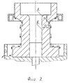
На фиг. 1 показан общий вид устройства, на фиг.2 - схема замера температур на внутренней поверхности контейнера при выборе оптимальной толщины стенок в зоне формирования переходного от стержня к фланцу участка отливки. In FIG. 1 shows a General view of the device, figure 2 is a diagram of measuring temperatures on the inner surface of the container when choosing the optimal wall thickness in the zone of formation of the transition from the rod to the flange of the casting section.
Устройство включает металлический контейнер 1 для заливки расплава 2, соответствующий форме отливки 3, состоящей из цилиндрического стержня 4 и развитого фланца 5, и имеющий внутренние 6 и наружные 8 поверхности, образующие его стенки "а". Стенки "а" контейнера 1 в зоне 12 формирования переходного от стержня к фланцу участка отливки 3 имеют толщину, равную 0,5-0,6 от диаметра стержня 4 отливки 3. Участок 13 наружной поверхности 8 контейнера 1 в зоне 14 формирования фланца выполнен с углом наклона, исключающим каплеотделение от стенок контейнера 1. The device includes a metal container 1 for pouring melt 2, corresponding to the shape of the casting 3, consisting of a cylindrical rod 4 and a developed flange 5, and having inner 6 and outer 8 surfaces forming its walls "a". The walls "a" of the container 1 in the zone 12 of forming the transition from the rod to the flange of the casting portion 3 have a thickness equal to 0.5-0.6 of the diameter of the rod 4 of the casting 3. Section 13 of the outer surface 8 of the container 1 in the zone 14 of the formation of the flange is made with angle of inclination, eliminating droplet separation from the walls of the container 1.
Устройство включает также пуансон 7, спрейер 10, выталкиватель отливок 15, стол-ванну 16 с отверстием 17, термопару 18, связанную с прибором 19. The device also includes a punch 7, a sprayer 10, a pusher castings 15, a table-bath 16 with a
Работа устройства происходит следующим образом. The operation of the device is as follows.
В металлический контейнер 1 заливают расплав 2. Далее осуществляют оформление отливки 3, имеющей цилиндрический стержень 4 и развитый фланец 5, по внутренней поверхности 6 контейнера 1 погружением в расплав пуансона 7, который удерживают в расплаве до затвердевания отливки 3. При этом наружную поверхность 8 контейнера 1 охлаждают ниспадающим потоком охлаждающей жидкости 9, омывающей контейнер, с помощью спрейера 10. The melt 2 is poured into the metal container 1. Next, the casting 3, having a cylindrical rod 4 and a developed flange 5, is formed on the inner surface 6 of the container 1 by immersion in the melt of the punch 7, which is held in the melt until the casting 3 hardens. The outer surface 8 of the container 1 is cooled by a flow of coolant 9, washing the container, using a sprayer 10.
При этом также производят местную интенсификацию охлаждения контейнера в зоне 12 формирования переходного от стержня к фланцу участка отливки 3 перед заливкой, обеспечивая оптимальную в пределах 150-260oC температуру в указанной зоне на внутренней поверхности контейнера за счет толщины стенки "а" контейнера 1 в указанной зоне.At the same time, local intensification of the container cooling is carried out in the zone 12 of forming the transition from the rod to the flange of the casting section 3 before pouring, providing an optimum temperature in the specified area on the inner surface of the container within 150-260 o C due to the wall thickness "a" of the container 1 in specified zone.
При этом расположенный над потоком омывающей жидкости 9 участок 13 наружной поверхности контейнера в зоне 14 формирования фланца отливки выполняют с углом наклона "α", который исключает каплеотделение от стенок контейнера. In this case, the portion 13 of the outer surface of the container located in the region 14 of the formation of the casting flange located above the flow of the washing liquid 9 is performed with an inclination angle "α", which eliminates droplet separation from the container walls.
Далее из контейнера 1 извлекают пуансон 7 и удаляют отливку 3 с помощью выталкивателя 15. При этом продолжают охлаждение наружной поверхности 8 контейнера 1. При этом также возвращают выталкиватель 15 в исходное положение и наносят технологическую смазку на внутреннюю поверхность 6 контейнера 1, например, распылением с помощью форсунки (на фиг. не показана). После достижения требуемых технологических температур на внутренней поверхности 6 контейнера 1 осуществляют очередную заливку в него расплава. При охлаждении жидкость 9 попадает в стол-ванну 16 и через отверстие 17 удаляется из контейнера 1. Для контроля температурного режима в контейнер 1 устанавливают термопару 18, связанную с прибором 19. Next, the punch 7 is removed from the container 1 and the casting 3 is removed using the ejector 15. The cooling of the outer surface 8 of the container 1 is continued. The ejector 15 is also returned to its original position and technological lubricant is applied to the inner surface 6 of the container 1, for example, by spraying with using nozzles (not shown in FIG.). After reaching the required process temperatures on the inner surface 6 of the container 1, another melt is poured into it. When cooling, the liquid 9 enters the table-bath 16 and through the
КОНКРЕТНЫЙ ПРИМЕР РАБОТЫ УСТРОЙСТВА
Получали отливку из алюминиевого сплава АК12М штамповкой жидкого металла. Высота отливки - 98 мм, диаметр фланца - 91 мм, диаметр ее стержня - 36,5 мм. Температура расплава - 680...700oC. Темп получения отливок - 27 сек. Время затвердевания отливки под давлением - 8 сек. Технологическая графитовая смазка ОГВ - 75 в разбавлении с водой 1:10 наносилась на внутреннюю поверхность контейнера с помощью форсунки в течение 3 сек. Контроль температуры на внутренней поверхности контейнера производили контактной хромель-копелевой термопарой непосредственно перед заливкой расплава. Точка контроля "в" (фиг. 2) находилась на внутренней поверхности контейнера в зоне формирования стержня отливки и на расстоянии 40...50 мм от ее нижнего торца. Точка контроля "г" находилась на внутренней поверхности контейнера в зоне формирования переходного от стержня к фланцу участка отливки.SPECIFIC EXAMPLE OF DEVICE OPERATION
Received casting of aluminum alloy AK12M stamping liquid metal. The height of the casting is 98 mm, the diameter of the flange is 91 mm, the diameter of its core is 36.5 mm. The melt temperature is 680 ... 700 o C. The rate of casting is 27 seconds. The solidification time of the casting under pressure is 8 seconds. Technological graphite grease OGV - 75 in a dilution with water 1:10 was applied to the inner surface of the container using a nozzle for 3 seconds. Temperature control on the inner surface of the container was carried out using a contact chromel-kopel thermocouple immediately before pouring the melt. The control point "c" (Fig. 2) was located on the inner surface of the container in the zone of formation of the casting rod and at a distance of 40 ... 50 mm from its lower end. The control point "g" was on the inner surface of the container in the zone of formation of the transition from the rod to the flange of the casting site.
Теплоотвод от наружной поверхности контейнера производили ниспадающим потоком охлаждающей жидкости, омывающей контейнер. Heat removal from the outer surface of the container was carried out by a flow of coolant washing the container.
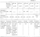
В контейнере, имеющем толщину стенок 24,5 мм, производили местное утонение стенок в зоне формирования переходного от стержня к фланцу участка отливки, толщину "а" которых в вышеназванной зоне выполняли различной по отношению к диаметру "d" стержня отливки с целью определения оптимального значения. Расположенный над потоком омывающей жидкости участок наружной поверхности контейнера в зоне формирования фланца выполняли с углом наклона "α", который составлял 60 градусов по отношению к вертикальной, оси. Результаты см. в таблице 1. In a container having a wall thickness of 24.5 mm, local thinning of the walls was carried out in the zone of formation of the casting section transitional from the rod to the flange, the thickness "a" of which in the above zone was performed different with respect to the diameter "d" of the casting rod in order to determine the optimal value . The portion of the outer surface of the container located above the washer fluid flow in the flange formation zone was performed with an inclination angle "α", which was 60 degrees with respect to the vertical axis. The results are shown in table 1.
Как видно из таблицы N 1, при толщине стенок в зоне местного утонения в пределах 0,50. ..0,60 от диаметра стержня отливки качество отливок удовлетворительное. При этом температура в точке "г" находилась в пределах оптимальных значений 150...260oC. При толщине стенок более 0,60 от диаметра стержня отливки, а также при отсутствии местного утонения стенок, в сердцевине отливки наблюдалась микропористость, а на поверхности надиры. При этом температура в точке "г" была выше 260oC. При толщине стенок менее 0,50 от диаметра стержня отливки излишнее местное переохлаждение проявляется в виде частичной непроштамповки. При этом температура в точке "г" была ниже 150oC.As can be seen from table No. 1, with a wall thickness in the zone of local thinning within 0.50. ..0.60 of the diameter of the casting rod, the quality of the castings is satisfactory. The temperature at point "g" was within the optimal range of 150 ... 260 o C. With a wall thickness of more than 0.60 of the diameter of the casting rod, as well as in the absence of local thinning of the walls, microporosity was observed in the core of the casting, and on the surface nadir. The temperature at point "g" was above 260 o C. With a wall thickness of less than 0.50 of the diameter of the casting rod, excessive local supercooling manifests itself in the form of partial non-stamping. The temperature at the point "g" was below 150 o C.
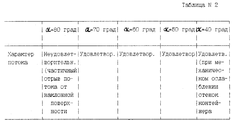
Отдельно производили сценку влияния угла наклона "α", расположенного над потоком омывающей жидкости участка наружной поверхности контейнера в зоне формирования фланца на характер потока омывающей жидкости. Результаты см. в таблице 2. Separately, a scene was made of the influence of the angle of inclination "α" located above the washer fluid flow of the portion of the outer surface of the container in the flange formation zone on the nature of the washer fluid flow. The results are shown in table 2.
Как видно из таблицы N 2, при угле "α" в пределах 50...70o, характер потока удовлетворительный, поток имеет непрерывный характер и омывает все охлаждаемые поверхности, включая поверхность с наклоном, расположенную над потоком. Каплеотделение от стенок контейнера отсутствует. При угле "α" более 70o непрерывность потока нарушается, что проявляется в его частичном отрыве от поверхности с наклоном, расположенной над потоком. При угле "α" менее 50o поток непрерывен, однако при этом имеет место механическое ослабление (излишнее утонение) стенок контейнера в зоне формирования фланца отливки.As can be seen from table N 2, at an angle "α" within 50 ... 70 o , the nature of the flow is satisfactory, the flow is continuous and washes all cooled surfaces, including a surface with a slope located above the flow. There is no droplet separation from the container walls. When the angle "α" more than 70 o the continuity of the flow is violated, which is manifested in its partial separation from the surface with a slope located above the stream. When the angle "α" less than 50 o the stream is continuous, however, there is a mechanical weakening (excessive thinning) of the walls of the container in the zone of formation of the casting flange.
Преимуществом устройства является расширение технологических возможностей за счет получения отливок стержней с развитым фланцем, что достигается за счет исключения перегрева внутренней поверхности контейнера в зоне формирования переходного от стержня к фланцу участка отливки. The advantage of the device is the expansion of technological capabilities due to the production of castings of rods with a developed flange, which is achieved by eliminating overheating of the inner surface of the container in the formation zone of the casting section transitional from the rod to the flange.
Claims (1)
Priority Applications (1)
| Application Number | Priority Date | Filing Date | Title |
|---|---|---|---|
| RU98109229A RU2138363C1 (en) | 1998-05-12 | 1998-05-12 | Apparatus for producing core castings with wide flange |
Applications Claiming Priority (1)
| Application Number | Priority Date | Filing Date | Title |
|---|---|---|---|
| RU98109229A RU2138363C1 (en) | 1998-05-12 | 1998-05-12 | Apparatus for producing core castings with wide flange |
Publications (2)
| Publication Number | Publication Date |
|---|---|
| RU98109229A RU98109229A (en) | 1999-09-20 |
| RU2138363C1 true RU2138363C1 (en) | 1999-09-27 |
Family
ID=20206019
Family Applications (1)
| Application Number | Title | Priority Date | Filing Date |
|---|---|---|---|
| RU98109229A RU2138363C1 (en) | 1998-05-12 | 1998-05-12 | Apparatus for producing core castings with wide flange |
Country Status (1)
| Country | Link |
|---|---|
| RU (1) | RU2138363C1 (en) |
Citations (3)
| Publication number | Priority date | Publication date | Assignee | Title |
|---|---|---|---|---|
| GB1337732A (en) * | 1970-01-21 | 1973-11-21 | Ass Eng Ltd | Method of casting pistons |
| GB1337731A (en) * | 1970-01-21 | 1973-11-21 | Ass Eng Ltd | Casting method and apparatus |
| SU504463A3 (en) * | 1972-11-14 | 1976-02-25 | Карл Шмидт Гмбх (Фирма) | Kokil |
-
1998
- 1998-05-12 RU RU98109229A patent/RU2138363C1/en active
Patent Citations (3)
| Publication number | Priority date | Publication date | Assignee | Title |
|---|---|---|---|---|
| GB1337732A (en) * | 1970-01-21 | 1973-11-21 | Ass Eng Ltd | Method of casting pistons |
| GB1337731A (en) * | 1970-01-21 | 1973-11-21 | Ass Eng Ltd | Casting method and apparatus |
| SU504463A3 (en) * | 1972-11-14 | 1976-02-25 | Карл Шмидт Гмбх (Фирма) | Kokil |
Non-Patent Citations (1)
| Title |
|---|
| Словарь-справочник по литейному производству. - М.: Машиностроение, 1990, с.292. РЖ "Технология машиностроения". 1987, N 2, реферат 2Г282П. Цветное литье. Справочник. - М,: Машиностроение, 1989, с.333. * |
Similar Documents
| Publication | Publication Date | Title |
|---|---|---|
| US4494594A (en) | Spray cooling system for continuous steel casting machine | |
| US2946100A (en) | Block graphite mold for continuous casting | |
| US3212142A (en) | Continuous casting system | |
| CA1139529A (en) | Method for continuous casting of metallic strands at exceptionally high speeds | |
| EP0570751B1 (en) | Cooling method and apparatus for continuous casting and its mold | |
| US4483385A (en) | System for oscillating mold tube in continuous steel casting machine | |
| RU2138363C1 (en) | Apparatus for producing core castings with wide flange | |
| US3710840A (en) | Method for continuous casting of hollow bar | |
| US3344846A (en) | Apparatus for continuously horizontally casting high melting metals, particularly steel | |
| SU1215607A3 (en) | Device for continuous casting of thin-walled cast-iron pipe | |
| US3321008A (en) | Apparatus for the continuous casting of metal | |
| US3460609A (en) | Nozzle for supplying melt to a mould in a continuous casting machine | |
| US4460034A (en) | Mold for continuous casting | |
| US2754556A (en) | Method and means of continuous casting of light metals | |
| JPH0255642A (en) | Method and device for continuously casting strip steel | |
| RU2093299C1 (en) | Method for production of continuously cast hollow bimetallic blanks | |
| TWI876159B (en) | Starting head for a continuous casting mold and continuous casting mold system | |
| US4205716A (en) | Continuous casting process and apparatus for production of metallic hollow ingot | |
| EP0542030B1 (en) | Apparatus for intensifying cooling in the casting of metal objects | |
| US11691195B2 (en) | System, apparatus, and method for a direct chill casting cooling water spray pattern | |
| SU1166887A1 (en) | Cooled drift-pin for continuous horizontal casting of bars from copper-based alloys | |
| SU1281339A1 (en) | Mould | |
| Stulov et al. | Production of Steel Castings in Cylindrical Molds | |
| RU100931U1 (en) | DEVICE FOR CASTING ROLL BARS FROM ALUMINUM AND ALUMINUM ALLOYS | |
| KR100515460B1 (en) | Continuous casting ingot mould for the vertical casting of metals |