RU2139192C1 - Method of and machine for building cautochouc pneumatic tyre - Google Patents
Method of and machine for building cautochouc pneumatic tyre Download PDFInfo
- Publication number
- RU2139192C1 RU2139192C1 RU93036961/12A RU93036961A RU2139192C1 RU 2139192 C1 RU2139192 C1 RU 2139192C1 RU 93036961/12 A RU93036961/12 A RU 93036961/12A RU 93036961 A RU93036961 A RU 93036961A RU 2139192 C1 RU2139192 C1 RU 2139192C1
- Authority
- RU
- Russia
- Prior art keywords
- thread
- base
- tire
- cord
- laying
- Prior art date
Links
Images

Classifications
-
- B—PERFORMING OPERATIONS; TRANSPORTING
- B29—WORKING OF PLASTICS; WORKING OF SUBSTANCES IN A PLASTIC STATE IN GENERAL
- B29D—PRODUCING PARTICULAR ARTICLES FROM PLASTICS OR FROM SUBSTANCES IN A PLASTIC STATE
- B29D30/00—Producing pneumatic or solid tyres or parts thereof
- B29D30/06—Pneumatic tyres or parts thereof (e.g. produced by casting, moulding, compression moulding, injection moulding, centrifugal casting)
- B29D30/08—Building tyres
- B29D30/20—Building tyres by the flat-tyre method, i.e. building on cylindrical drums
- B29D30/30—Applying the layers; Guiding or stretching the layers during application
- B29D30/3035—Applying the layers; Guiding or stretching the layers during application by feeding a continuous band and moving it back and forth (zig-zag) to form an annular element
-
- B—PERFORMING OPERATIONS; TRANSPORTING
- B29—WORKING OF PLASTICS; WORKING OF SUBSTANCES IN A PLASTIC STATE IN GENERAL
- B29C—SHAPING OR JOINING OF PLASTICS; SHAPING OF MATERIAL IN A PLASTIC STATE, NOT OTHERWISE PROVIDED FOR; AFTER-TREATMENT OF THE SHAPED PRODUCTS, e.g. REPAIRING
- B29C53/00—Shaping by bending, folding, twisting, straightening or flattening; Apparatus therefor
- B29C53/56—Winding and joining, e.g. winding spirally
- B29C53/58—Winding and joining, e.g. winding spirally helically
- B29C53/583—Winding and joining, e.g. winding spirally helically for making tubular articles with particular features
- B29C53/588—Winding and joining, e.g. winding spirally helically for making tubular articles with particular features having a non-linear axis, e.g. elbows, toroids
-
- B—PERFORMING OPERATIONS; TRANSPORTING
- B29—WORKING OF PLASTICS; WORKING OF SUBSTANCES IN A PLASTIC STATE IN GENERAL
- B29C—SHAPING OR JOINING OF PLASTICS; SHAPING OF MATERIAL IN A PLASTIC STATE, NOT OTHERWISE PROVIDED FOR; AFTER-TREATMENT OF THE SHAPED PRODUCTS, e.g. REPAIRING
- B29C53/00—Shaping by bending, folding, twisting, straightening or flattening; Apparatus therefor
- B29C53/80—Component parts, details or accessories; Auxiliary operations
- B29C53/8008—Component parts, details or accessories; Auxiliary operations specially adapted for winding and joining
- B29C53/8016—Storing, feeding or applying winding materials, e.g. reels, thread guides, tensioners
-
- B—PERFORMING OPERATIONS; TRANSPORTING
- B29—WORKING OF PLASTICS; WORKING OF SUBSTANCES IN A PLASTIC STATE IN GENERAL
- B29D—PRODUCING PARTICULAR ARTICLES FROM PLASTICS OR FROM SUBSTANCES IN A PLASTIC STATE
- B29D30/00—Producing pneumatic or solid tyres or parts thereof
- B29D30/06—Pneumatic tyres or parts thereof (e.g. produced by casting, moulding, compression moulding, injection moulding, centrifugal casting)
- B29D30/08—Building tyres
-
- B—PERFORMING OPERATIONS; TRANSPORTING
- B29—WORKING OF PLASTICS; WORKING OF SUBSTANCES IN A PLASTIC STATE IN GENERAL
- B29D—PRODUCING PARTICULAR ARTICLES FROM PLASTICS OR FROM SUBSTANCES IN A PLASTIC STATE
- B29D30/00—Producing pneumatic or solid tyres or parts thereof
- B29D30/06—Pneumatic tyres or parts thereof (e.g. produced by casting, moulding, compression moulding, injection moulding, centrifugal casting)
- B29D30/08—Building tyres
- B29D30/10—Building tyres on round cores, i.e. the shape of the core is approximately identical with the shape of the completed tyre
- B29D30/16—Applying the layers; Guiding or stretching the layers during application
- B29D30/1635—Applying the layers; Guiding or stretching the layers during application by feeding a continuous band and moving it back and forth (zig-zag) to form an annular element
-
- B—PERFORMING OPERATIONS; TRANSPORTING
- B29—WORKING OF PLASTICS; WORKING OF SUBSTANCES IN A PLASTIC STATE IN GENERAL
- B29D—PRODUCING PARTICULAR ARTICLES FROM PLASTICS OR FROM SUBSTANCES IN A PLASTIC STATE
- B29D30/00—Producing pneumatic or solid tyres or parts thereof
- B29D30/06—Pneumatic tyres or parts thereof (e.g. produced by casting, moulding, compression moulding, injection moulding, centrifugal casting)
- B29D30/70—Annular breakers
-
- B—PERFORMING OPERATIONS; TRANSPORTING
- B29—WORKING OF PLASTICS; WORKING OF SUBSTANCES IN A PLASTIC STATE IN GENERAL
- B29D—PRODUCING PARTICULAR ARTICLES FROM PLASTICS OR FROM SUBSTANCES IN A PLASTIC STATE
- B29D30/00—Producing pneumatic or solid tyres or parts thereof
- B29D30/06—Pneumatic tyres or parts thereof (e.g. produced by casting, moulding, compression moulding, injection moulding, centrifugal casting)
- B29D30/08—Building tyres
- B29D30/10—Building tyres on round cores, i.e. the shape of the core is approximately identical with the shape of the completed tyre
- B29D30/16—Applying the layers; Guiding or stretching the layers during application
- B29D2030/1664—Details, accessories or auxiliary operations not provided for in the other subgroups of B29D30/00
- B29D2030/1678—Details, accessories or auxiliary operations not provided for in the other subgroups of B29D30/00 the layers being applied being substantially continuous, i.e. not being cut before the application step
Landscapes
- Engineering & Computer Science (AREA)
- Mechanical Engineering (AREA)
- Physics & Mathematics (AREA)
- Nonlinear Science (AREA)
- Tyre Moulding (AREA)
- Wire Processing (AREA)
- Ropes Or Cables (AREA)
- Processing And Handling Of Plastics And Other Materials For Molding In General (AREA)
Abstract
Description
Изобретение касается технологии изготовления покрышек пневматических шин. Говоря более конкретно, это изобретение относится к размещению и укладке кордных нитей в процессе создания подкрепляющей конструкции покрышки пневматической шины, например в процессе создания ее силового каркаса. The invention relates to a manufacturing technology for pneumatic tire tires. More specifically, this invention relates to the placement and laying of cord threads in the process of creating a reinforcing structure of a tire of a pneumatic tire, for example in the process of creating its power cage.
В этой области техники уже известны многочисленные способы и специальные станки для их практической реализации, которые дают возможность интегрировать процесс изготовления силового каркаса покрышки пневматической шины в технологический процесс сборки самой этой покрышки. Это означает, что вместо того, чтобы прибегать к использованию полуфабрикатов или заготовок упомянутого выше силового каркаса, таких, например, как полотна или куски слоев этого силового каркаса, осуществляется изготовление одного или нескольких сразу подкрепляющих элементов такого силового каркаса прямо по месту, в процессе изготовления и сборки самой покрышки, причем упомянутые выше элементы силового каркаса изготавливаются из одной длинной и непрерывной нити корда, размещаемой на одной катушке. Известно, например, техническое решение подобного рода, описанное в американском патенте US 4795523. Однако, несмотря на то, что упомянутое техническое решение представляет собой значительный технологический прогресс по сравнению с традиционно используемыми технологиями шинного производства, которые обращаются к использованию предварительно заготовленных полотен корда силового каркаса покрышки, оно обладает и существенным недостатком, который состоит в том, что станок, специально разработанный для практической реализации предложенного способа, может быть применен только для изготовления покрышек, всегда имеющих одно и то же количество кордной нити в изготавливаемой таким образом подкрепляющей конструкции, например, всегда одно и то же число радиальных дуг или полукружий в силовом каркасе покрышки радиального типа. Numerous methods and special machines for their practical implementation are already known in this technical field, which make it possible to integrate the manufacturing process of the power frame of a pneumatic tire tire into the assembly process of this tire itself. This means that, instead of resorting to the use of semi-finished products or blanks of the aforementioned power cage, such as, for example, sheets or pieces of layers of this power cage, one or more immediately reinforcing elements of such a power cage are produced directly in place, during the manufacturing process and assemblies of the tire itself, wherein the aforementioned elements of the power cage are made of one long and continuous cord thread placed on one coil. For example, a technical solution of this kind is known, which is described in US patent US 4795523. However, despite the fact that the mentioned technical solution represents significant technological progress compared to traditionally used tire manufacturing technologies, which refer to the use of pre-prepared power cord cords tires, it also has a significant drawback, which is that the machine, specially designed for the practical implementation of the proposed of the method can only be used for the manufacture of tires, always having the same amount of cord thread in the reinforcing structure manufactured in this way, for example, always the same number of radial arcs or semicircles in the power frame of a radial type tire.
На сегодняшний день известно также другое техническое решение, описанное в американском патенте US 4952259. Это технологическое предложение, которое основано на пробрасывании кордной нити наподобие удара ременным бичом, позволяет оплетать текущие углы располагающихся непосредственно под беговой дорожкой протектора полотен каркаса. Оно позволяет также создавать силовые элементы каркаса покрышки, в которых кордная нить без разрыва проходит от одного борта покрышки к другому. Однако упомянутое техническое решение позволяет лишь с большими трудностями достигать малых углов, которые в ряде случаев имеют место в некоторых силовых элементах вершины покрышки или брекера. Напомним, что эти углы измеряются по отношению к опорной системе координат, определяемой плоскостью, перпендикулярной оси вращения шины, по твердо установленным правилам, не вызывающим разногласий. To date, another technical solution is also known, which is described in US patent US 4952259. This technological proposal, which is based on throwing a cord thread like a belt whip, allows you to braid the current corners of the carcass canvases located directly under the treadmill. It also allows you to create power elements of the tire carcass, in which the cord thread without a gap passes from one side of the tire to another. However, the mentioned technical solution allows only with great difficulty to achieve small angles, which in some cases take place in some power elements of the top of the tire or breaker. Recall that these angles are measured with respect to the reference coordinate system defined by a plane perpendicular to the axis of rotation of the tire, according to well-established rules that do not cause controversy.
Цель настоящего изобретения состоит в том, чтобы предложить такой способ изготовления силового каркаса покрышки пневматической шины, который позволяет реализовать из одной длинной и непрерывной кордной нити все силовые элементы каркаса, а также большую часть силовых элементов вершины покрышки или брекера, то есть тех силовых элементов, которые располагаются непосредственно под беговой дорожкой протектора и где угол, который образуют кордные нити этих силовых элементов с плоскостью, перпендикулярной оси вращения шины, существенно отличается от нуля градусов. The purpose of the present invention is to provide such a method of manufacturing a power carcass of a tire of a pneumatic tire, which makes it possible to realize from one long and continuous cord thread all the power elements of the carcass, as well as most of the power elements of the top of the tire or belt, that is, those power elements, which are located directly below the treadmill and where the angle that the cord threads of these power elements form with a plane perpendicular to the axis of rotation of the tire is significantly different differs from zero degrees.
Другая цель данного изобретения состоит в том, чтобы предложить способ, который позволяет изготовить силовой элемент покрышки пневматической шины из любого числа кордных нитей, какое только может потребоваться для реализации этого силового элемента. Another objective of the present invention is to propose a method that allows you to make a power element of the tire of the pneumatic tire from any number of cord threads, which may be required to implement this power element.
Еще одна цель настоящего изобретения состоит в том, чтобы специальный станок, который должен практически осуществлять предложенный способ изготовления силовых элементов каркаса покрышки, был механически предельно простым и легким по весу и чтобы этот станок требовал выполнения минимального объема по возможности простых и малотрудоемких регулировочных операций для перенастройки его на любые возможные варианты силовых каркасов для всей номенклатуры выпускаемых покрышек пневматических шин, обеспечивая при этом возможно более широкий диапазон этой номенклатуры. Another objective of the present invention is that a special machine, which should practically implement the proposed method for the manufacture of power elements of the carcass of the tire, be mechanically extremely simple and light in weight and that this machine requires a minimum amount of possible simple and low-labor adjustment operations for reconfiguration it to any possible options for power cages for the entire range of pneumatic tire covers, while providing the widest possible the range of this item.
В соответствии с предлагаемым изобретением способ изготовления каучуковой покрышки пневматической шины, состоящий в наложении на специальное основание, поверхность которого имеет форму, в точности совпадающую с формой внутренней поверхности упомянутой выше покрышки, различных компонентов на предназначенные для них места, определяемые "архитектурой" данной покрышки, причем кордная нить силового каркаса, накладываемая на упомянутое выше специальное основание, удерживается на нем при помощи адгезии или приклеивания. Предлагаемый способ отличается тем, что кордная нить силового каркаса покрышки укладывается на основание с помощью специального направляющего органа или водителя нити, перемещающегося в пространстве, располагающемся непосредственно над трассой, которую данная кордная нить займет на поверхности упомянутого основания после того, как она будет к нему прижата. При этом упомянутый выше направляющий орган водит или направляет кордную нить со скольжением по ней. Предлагаемый способ отличается также тем, что этот упомянутый выше направляющий орган или водитель кордной нити приводится в движение, позволяющее обматывать этой кордной нитью упомянутое выше специальное основание, переводя нить с одной стороны основания на другую, а затем и обратно, и продолжает это движение от одного витка к другому совместно с относительным круговым движением основания и направляющего органа, обеспечивающим их относительное смещение за один цикл намотки на величину, соответствующую шагу укладки кордной нити на поверхность основания, таким образом, чтобы нить образовывала на этой поверхности примыкающие друг к другу дуги. In accordance with the invention, a method for manufacturing a rubber tire of a pneumatic tire, which is applied to a special base, the surface of which has a shape that exactly matches the shape of the inner surface of the tire mentioned above, of various components in the places intended for them, determined by the "architecture" of the tire moreover, the cord thread of the power frame, superimposed on the above-mentioned special base, is held thereon by adhesion or gluing. The proposed method is characterized in that the cord thread of the power carcass of the tire is laid on the base using a special guiding body or driver of the thread moving in a space located directly above the track, which this cord thread will occupy on the surface of the mentioned base after it is pressed against it . In this case, the aforementioned guide body leads or guides the cord thread with sliding along it. The proposed method is also characterized in that this guide body or cord driver mentioned above is set in motion, allowing the above-mentioned special base to be wound with this cord, transferring the thread from one side of the base to the other and then back, and continues this movement from one turn to another together with the relative circular motion of the base and the guide body, providing their relative displacement in one winding cycle by an amount corresponding to the step of laying the cord on the surface of the base, so that the thread forms on this surface adjacent to each other arcs.
Итак, основной цикл практической реализации способа в соответствии с предлагаемым изобретением содержит следующие этапы:
- укладка кордной нити на основание в некоторой отправной точке, соответствующей краю дуги или витка, и приклеивание ее в этом месте к упомянутому выше основанию;
- перемещение упомянутого выше направляющего органа или водителя кордной нити, скользящего вдоль этой нити, над поверхностью основания по дугообразной траектории от упомянутой выше отправной точки до некоторой конечной точки, соответствующей другому краю той же самой дуги;
- прижатие и приклеивание кордной нити к основанию в упомянутой выше конечной точке дуги.So, the main cycle of the practical implementation of the method in accordance with the invention contains the following steps:
- laying the cord on the base at some starting point corresponding to the edge of the arc or turn, and gluing it in this place to the above-mentioned base;
- the movement of the aforementioned guide body or the driver of the cord thread sliding along this thread, above the base surface along an arcuate path from the aforementioned starting point to a certain end point corresponding to another edge of the same arc;
- pressing and gluing the cord to the base at the end point of the arc mentioned above.
Этот цикл операций повторяется попеременно слева направо и справа налево в пространстве над поверхностью основания. При этом упомянутое основание смещается по отношению к направляющему органу на расстояние, соответствующее шагу укладки кордной нити в данный элемент силового каркаса покрышки, между двумя взаимно противоположными перемещениями упомянутого выше направляющего органа. This cycle of operations is repeated alternately from left to right and from right to left in space above the base surface. In this case, the said base is displaced with respect to the guide body by a distance corresponding to the step of laying the cord thread in a given element of the tire power cage between two mutually opposite movements of the guide body mentioned above.
В своем мгновенном движении в каждый данный момент времени направляющий орган располагается в плоскости, проходящей через трассу, которую займет кордная нить, когда она будет уложена на основание. Для того, чтобы уложить дугу из кордной нити, которая будет определять плоскость на поверхности предполагаемого неподвижным основания, упомянутый выше направляющий орган и вектор скорости его движения постоянно должны находиться в этой плоскости. Это обстоятельство и определяет принцип укладки кордной нити в соответствии с предлагаемым изобретением. Для того, чтобы учесть движение основания в процессе укладки кордной нити или для того, чтобы уложить дугу, которая не вписывается в плоскость, здесь можно иметь небольшие отклонения от этой теоретической плоскости, как это будет показано в продолжении настоящего описания изобретения. In its instantaneous movement at any given moment in time, the guiding body is located in a plane passing through the path that the cord takes up when it is laid on the base. In order to lay an arc of cord cord, which will determine the plane on the surface of the supposedly fixed base, the above-mentioned guide body and the velocity vector of its movement must constantly be in this plane. This circumstance determines the principle of laying cord cord in accordance with the invention. In order to take into account the movement of the base in the process of laying the cord or in order to lay an arc that does not fit into the plane, there may be slight deviations from this theoretical plane, as will be shown in the continuation of the present description of the invention.
Общее движение направляющего органа представляет собой попеременное возвратно-поступательное движение. В предпочтительном варианте практической реализации предлагаемого способа при каждом изменении направления движения упомянутого выше направляющего органа кордная нить удерживается в контакте с основанием путем прижатия ее к нему с помощью специального прижимного органа. The general movement of the guide body is an alternating reciprocating motion. In a preferred embodiment, the practical implementation of the proposed method, with each change in the direction of movement of the above-mentioned guide body, the cord thread is kept in contact with the base by pressing it to it using a special clamping body.
В данном описании под выражением "изготовление покрышки пневматической камеры" понимается как полное, так и частичное изготовление силового каркаса покрышки, если по меньшей мере один силовой элемент этого каркаса изготавливается в соответствии со способом, предложенным в данном изобретении. Само собой разумеется, что используемый в описании предлагаемого изобретение термин "нить" должен пониматься в самом общем смысле и охватывать такие понятия, как моноволокно, мультиволокно, различные соединения волокон или собственно нити, такие, например, как кордная нить или крученая нить, независимо от того, из какого материала они сделаны. In this description, the expression "manufacturing a tire of a pneumatic chamber" means both complete and partial manufacture of a power frame of a tire, if at least one power element of this frame is made in accordance with the method proposed in this invention. It goes without saying that the term “thread” used in the description of the invention should be understood in the most general sense and cover such concepts as monofilament, multifiber, various fiber compounds or the actual thread, such as, for example, cord thread or twisted thread, regardless of of what material they are made of.
В данном описании термин "дуга" используется для обозначения участка или отрезка нити, проходящего от одной особой точки до другой в силовой арматуре покрышки. Совокупность этих дуг из кордной нити, располагающихся по всей окружности покрышки, образует собственно силовой каркас этой покрышки. В определенном здесь смысле дуга может составлять часть силового каркаса или часть подкрепляющего элемента верхней части протектора, или часть любого другого силового элемента каркаса или просто силового элемента любого типа. Эти дуги могут быть индивидуализированы путем обрезки нити в процессе ее укладки или же они все могут быть связаны между собой в окончательном силовом каркасе покрышки или какого-либо ее элемента. In this description, the term "arc" is used to denote a section or segment of thread extending from one particular point to another in the tire reinforcement. The combination of these arcs from the cord thread, located around the entire circumference of the tire, forms the actual power frame of this tire. In the sense defined here, the arc can be part of the power frame or part of the reinforcing element of the upper part of the tread, or part of any other power element of the frame or just a power element of any type. These arcs can be individualized by trimming the thread during its laying, or they can all be interconnected in the final power frame of the tire or any of its element.
Существенным является то обстоятельство, что предлагаемое изобретение трактует изготовление силового каркаса покрышки из одной длинной и непрерывной нити, снимаемой, например, с одной бобины. И неважно, что реально изготавливаемый силовой элемент, чтобы быть полным, может состоять из нескольких последовательных проходов с разрезанием нити между проходами или без ее разрезания. Significant is the fact that the present invention treats the manufacture of a power skeleton of a tire from one long and continuous thread, removed, for example, from one reel. And it doesn’t matter that a power element actually manufactured, in order to be complete, can consist of several successive passes with or without cutting the thread between the passages.
И наконец, когда в данном описании определяется положение, сторона или направление, для чего используются выражения "радиально", "в осевом направлении", "по окружности", или когда говорится о радиусе, за ориентир или репер принимается сердечник или специальное основание, на котором изготавливается покрышка пневматической шины, или же сама эта покрышка, что собственно одно и то же. Осью или точкой отсчета является здесь ось вращения сердечника или основания и его средняя точка, соответствующая центру тяжести. And finally, when the position, side or direction is determined in this description, for which the expressions “radially”, “in the axial direction”, “around the circumference” are used, or when the radius is referred to, the core or special base is taken as a reference point or reference point, which makes the tire of a pneumatic tire, or this tire itself, which is actually one and the same. The axis or reference point here is the axis of rotation of the core or base and its midpoint corresponding to the center of gravity.
Способ в соответствии с предлагаемым изобретением обладает и другим преимуществом: он позволяет без особенных затруднений создать силовой элемент, например силовой каркас покрышки, в котором шаг укладки нити будет переменным. Под выражением "шаг укладки" здесь понимается расстояние, представляющее собой сумму промежутка между двумя соседними нитями и диаметра данной нити. Хорошо известно, что для силового каркаса покрышки промежуток между нитями изменяется в зависимости от радиуса, на котором происходит измерение этого промежутка. В данном случае речь идет не об этом естественном изменении, но о действительно изменяемом шаге на данном радиусе. Для осуществления такого изменения достаточно без изменения ритма работы направляющих нить органов изменять в соответствии с любым требуемым в данном случае законом скорость вращения сердечника или основания. В ходе одного оборота скорость этого основания описывается синусоидальным законом так, что изменение шага является синусоидальным. Таким образом получают покрышку, нити силового каркаса который, например, для радиального каркаса, располагаются с шагом, представляющим контролируемое изменение для заданного радиального положения. The method in accordance with the invention has another advantage: it allows without special difficulties to create a power element, for example a power frame of the tire, in which the step of laying the thread will be variable. The term “laying step” here means the distance, which is the sum of the gap between two adjacent threads and the diameter of this thread. It is well known that for a tire power cage, the gap between the threads varies depending on the radius at which this gap is measured. In this case, we are not talking about this natural change, but about a truly variable step at a given radius. To implement such a change, it is sufficient to change the rotation speed of the core or base in accordance with any law required in this case without changing the rhythm of the work of the thread-guiding organs. During one revolution, the speed of this base is described by a sinusoidal law so that the change in pitch is sinusoidal. In this way, a tire is obtained, the threads of the power cage which, for example, for the radial cage, are arranged in increments representing a controlled change for a given radial position.
Данное изобретение предлагает также специальный станок, который позволяет практически реализовать предложенный способ изготовления силового каркаса покрышки пневматической шины. Поскольку нить подается специальным питателем, содержащим, например, одну бобину с нитью и орган контроля за натяжением снимаемой с бобины нити, станок для изготовления силового каркаса из единой длинной и непрерывной нити взаимодействует с основанием (жесткий сердечник или армированная мембрана), на котором изготавливается покрышка пневматической шины. The present invention also provides a special machine that can practically implement the proposed method for manufacturing a power carcass of a tire of a pneumatic tire. Since the thread is fed by a special feeder containing, for example, one bobbin with thread and a control element for the tension of the thread removed from the bobbin, the machine for manufacturing a power skeleton from a single long and continuous thread interacts with the base (hard core or reinforced membrane) on which the tire is made pneumatic tires.
Предлагаемый станок отличается тем, что он содержит
- направляющий орган со скольжением, в котором нить может свободно скользить;
- средства перемещения упомянутого выше направляющего органа по траектории его возвратно-поступательного движения;
- прижимные устройства, располагающиеся по меньшей мере на каждом конце упомянутой выше траектории возвратно-поступательного движения направляющего органа и предназначенные для прижатия нити к основанию.The proposed machine is characterized in that it contains
- sliding guide body, in which the thread can slide freely;
- means of moving the aforementioned guide body along the path of its reciprocating motion;
- clamping devices located at least at each end of the aforementioned path of the reciprocating movement of the guide body and designed to press the thread to the base.
Вся совокупность составных частей предлагаемого станка собрана таким образом, что когда нить прижимается и приклеивается к основанию благодаря срабатыванию соответствующего прижимного устройства, последующее перемещение упомянутого выше направляющего органа продлевает траекторию нити между упомянутым выше прижимным устройством и питателем нити, проводя эту нить над трассой, которую она займет на основании после укладки. Укладка нити на основание происходит постепенно позади направляющего органа не позднее того, как вступит в действие другое прижимное устройство, которое само осуществляет свою функцию прижатия нити к основанию до того, как начнется обратное движение направляющего органа вдоль траектории его возвратно-поступательного движения. The entire set of components of the proposed machine is assembled in such a way that when the thread is pressed and glued to the base due to the operation of the corresponding clamping device, the subsequent movement of the guide body mentioned above extends the path of the thread between the clamping device mentioned above and the thread feeder, conducting this thread over the path that it will take on the base after laying. The laying of the thread on the base occurs gradually behind the guide body no later than when another clamping device comes into operation, which itself performs its function of pressing the thread to the base before the reverse movement of the guide body along the path of its reciprocating movement begins.
Средство перемещения направляющего органа может быть образовано, например, гибким замкнутым ремнем, смонтированным в направляющем контуре (путь, представляющий собой замкнутую траекторию, по которой осуществляется движение направляющего органа), имеющем в целом вид дуги, охватывающей упомянутое выше основание. Этот контур позволяет практически реализовать возвратно-поступательное движение, предусмотренное способом в соответствии с предлагаемым изобретением, в особенно выгодном варианте, поскольку здесь отсутствует переменное движение: тангенциальная скорость упомянутого выше направляющего органа вдоль направляющего контура может быть постоянной. The means for moving the guide body can be formed, for example, by a flexible closed belt mounted in the guide loop (a path that represents a closed path along which the guide body moves), which has a generally arc-like shape, covering the aforementioned base. This contour makes it possible to practically realize the reciprocating motion provided by the method in accordance with the invention in a particularly advantageous embodiment, since there is no alternating motion: the tangential velocity of the aforementioned guide member along the guide contour can be constant.
Станок в соответствии с предлагаемым изобретением содержит специальное устройство формирования и регулировки положения упомянутого выше направляющего контура относительно используемого в данном случае основания, которое вводится внутрь этого контура между ветвями образуемой им дуги. The machine in accordance with the invention contains a special device for forming and adjusting the position of the aforementioned guide contour relative to the base used in this case, which is inserted into this contour between the branches of the arc formed by it.
Упомянутый выше направляющий орган может быть образован, например, поворотным ушком, закрепленным на упомянутом выше гибком ремне. В это ушко продевается кордная нить, из которой формируется силовой каркас покрышки. Ось вращения этого ушка перпендикулярна направляющему контуру и радиусу, проходящему через это ушко. На каждом конце упомянутой выше дуги, образуемой направляющим контуром, устанавливается прижимное устройство. Такая конструкция станка позволяет закреплять нить на каждом конце дуги и прижимать ее к основанию на всем протяжении этой дуги. The guide body mentioned above can be formed, for example, by a pivoting eye fixed to the above-mentioned flexible belt. A cord thread is threaded into this ear, from which the tire power frame is formed. The axis of rotation of this eye is perpendicular to the guide contour and the radius passing through this eye. A clamping device is installed at each end of the arc mentioned above, formed by a guide loop. This design of the machine allows you to fix the thread at each end of the arc and press it to the base along the entire length of this arc.
И наконец, предлагаемый станок содержит средства, позволяющие привести в движение гибкий ремень или ленту направляющего контура и привести во вращательное движение сердечник или основание, на котором формируется силовой каркас покрышки, со скоростью, являющейся функцией времени полного оборота упомянутого выше ушка направляющего органа по направляющему контуру и функцией требуемого шага укладки кордной нити в структуру силового каркаса покрышки. And finally, the proposed machine contains tools that allow you to set in motion a flexible belt or tape of the guide contour and rotate the core or base on which the power frame of the tire is formed, at a speed that is a function of the time of the complete revolution of the above-mentioned guide eye on the guide contour and the function of the required step of laying the cord in the structure of the power frame of the tire.
Здесь важно понять, что движение упомянутого выше основания не является необходимым параметром для практической реализации способа в соответствии с предлагаемым изобретением. Просто движение этого основания необходимо для того, чтобы следующие друг за другом дуги кордной нити, накладываемые на основание, располагались рядом друг с другом и соприкасались. Таким образом, амплитуда этого движения представляет собой функцию толщины используемой в данном случае кордной нити и необходимого промежутка между двумя соседними дугами из этой кордной нити. It is important to understand here that the movement of the base mentioned above is not a necessary parameter for the practical implementation of the method in accordance with the invention. Just the movement of this base is necessary so that successive arcs of cord cord, superimposed on the base, are located next to each other and in contact. Thus, the amplitude of this movement is a function of the thickness of the cord used in this case and the required gap between two adjacent arcs from this cord.
Описываемая ниже конструкция станка в соответствии с предлагаемым изобретением разработана специально для изготовления силового каркаса покрышки пневматической шины. Таким образом, дуга, которую описывает кордная нить, должна проходить от одного борта покрышки до другого. Такая дуга имеет форму буквы C. Если станок подобного типа разрабатывается специально для изготовления подкрепляющих элементов вершины покрышки, располагающихся непосредственно под беговой дорожкой протектора, то упомянутая выше дуга должна будет проходить от одной боковины покрышки до другой. Такая дуга будет иметь форму, похожую на круглую скобку. Само собой разумеется, что можно спроектировать и такой станок в соответствии с предлагаемым изобретением, который будет пригоден как для изготовления всего силового каркаса покрышки, так и для изготовления силовых элементов ее вершины. Об этом будет более подробно сказано в приведенном ниже описании изобретения и примера его практической реализации. The design of the machine described below in accordance with the invention is specially designed for the manufacture of the power frame of a pneumatic tire tire. Thus, the arc described by the cord must extend from one side of the tire to the other. Such an arc has the shape of the letter C. If a machine of this type is designed specifically for the manufacture of reinforcing elements of the tire tops located directly under the treadmill, the arc mentioned above will have to extend from one side of the tire to the other. Such an arc will have a shape similar to a parenthesis. It goes without saying that it is possible to design such a machine in accordance with the present invention, which will be suitable both for the manufacture of the entire power frame of the tire, and for the manufacture of power elements of its top. This will be discussed in more detail in the following description of the invention and an example of its practical implementation.
Направляющий контур станка в соответствии с предлагаемым изобретением искривлен таким образом, что он напоминает по форме букву C, как бы вложенную в букву Ω. Начав движение из некоторой исходной точки по C-образной кривой и дойдя до ее конечной точки, необходимо затем перейти на Ω -образную кривую для того, чтобы замкнуть описываемую направляющим контуром в пространстве фигуру, поскольку здесь в качестве направляющего контура используется так называемое "бесконечное" гибкое приводное средство. В приведенном ниже описании указано, что в рассматриваемом примере практической реализации станка в соответствии с предлагаемым изобретением в качестве такого гибкого бесконечного приводного средства использована роликовая цепь. Однако в этой роли могут выступать и другие эквивалентные по своим функциональным возможностям средства, такие, например, как соединенный в кольцо гибкий приводной ремень или трос, приводимые в движение без проскальзывания. Упомянутый выше направляющий контур в предпочтительном варианте практической реализации станка в соответствии с предлагаемым изобретением располагается в одной плоскости. The guiding circuit of the machine in accordance with the invention is curved in such a way that it resembles the shape of the letter C, as if embedded in the letter Ω. Starting from a certain starting point along a C-shaped curve and reaching its end point, you must then switch to an Ω-shaped curve in order to close the figure described by the guiding contour in space, since here the so-called “infinite” is used as the guiding contour flexible drive means. In the description below, it is indicated that in the example of practical implementation of the machine in accordance with the invention, a roller chain is used as such a flexible endless drive means. However, other equivalent means in terms of their functionality can play this role, such as, for example, a flexible drive belt or cable connected to a ring, driven without slipping. The above-mentioned guide circuit in a preferred embodiment of the practical implementation of the machine in accordance with the invention is located in the same plane.
Преимущество описанного выше расположения состоит в том, что оно позволяет охватить основание в требуемом диапазоне, то есть позволяет последовательно достигать двух противоположных точек этого основания, каждая из которых находится в зоне, соответствующей одному из бортов изготавливаемой покрышки, высвобождая при этом в центре направляющего контура максимум пространства для того, чтобы иметь возможность точно вставить в это пространство упомянутое выше основание. Станок, спроектированный в соответствии с этим принципом, оказывается способным укладывать на основание кордные нити, проходящие от одной боковины покрышки до другой, для формирования усилительного элемента под беговой дорожкой протектора даже в том случае, когда речь идет о широкой покрышке (для которой характерна малая величина отношения H-B, о чем еще будет сказано ниже) и малой величине угла укладки нити, что ведет к большой величине окружного промежутка между точкой, расположенной на одной боковине покрышки, и точкой, расположенной на другой боковине. The advantage of the arrangement described above is that it allows you to cover the base in the desired range, that is, it allows you to consistently reach two opposite points of this base, each of which is in the area corresponding to one of the sides of the tire being manufactured, while releasing a maximum in the center of the guide contour spaces in order to be able to accurately insert into this space the aforementioned base. The machine, designed in accordance with this principle, is able to lay cord threads on the base, passing from one side of the tire to the other, to form an reinforcing element under the treadmill, even when it comes to a wide tire (which is characterized by a small value relations HB, which will be discussed below) and a small value of the angle of laying of the thread, which leads to a large value of the circumferential gap between the point located on one side of the tire and the point located on another sidewall.
Регулировка положения упомянутого выше направляющего контура по отношению к основанию позволяет точно определить трассу укладки нити на это основание. В приведенном ниже описании речь идет о радиальной плоскости изготавливаемой покрышки, в которой располагается упомянутая выше трасса укладываемой кордной нити, поскольку в приведенном примере практической реализации предлагаемого изобретения описывается изготовление силового каркаса для радиальной покрышки, хотя, разумеется, это обстоятельство не является ни в коей мере ограничительным. Adjusting the position of the above-mentioned guide contour with respect to the base allows you to accurately determine the path of laying the thread on this base. In the description below, we are talking about the radial plane of the manufactured tire, in which the above-mentioned track of the stacked cord is located, since the example of the practical implementation of the invention describes the manufacture of a power frame for the radial tire, although, of course, this circumstance is not in any way restrictive.
В соответствии с предложенным способом упомянутый выше направляющий орган, то есть ушко в описанном ниже примере практической реализации станка в соответствии с предлагаемым изобретением, "облетает" основание, двигаясь довольно близко к требуемой трассе кордной нити в создаваемом силовом каркасе покрышки. При этом достаточно, чтобы кордная нить была приклеена к основанию в любой исходной точке на этой требуемой трассе. Последующее движение упомянутого выше ушка вдоль направляющего контура от исходной точки заставляет это ушко скрыться за основанием по отношению к этой исходной точке вследствие кривизны направляющего контура, то есть как бы уйти за горизонт. Как только это происходит, нить по необходимости укладывается на основание, поскольку она уже оказывается не в состоянии соединять исходную точку, где эта нить приклеена к основанию, с ушком направляющего органа, по прямой линии. Конструкция станка выполнена таким образом, что возвратно-поступательное движение направляющего органа связывает между собой наиболее удаленные друг от друга точки нити в изготавливаемом в данном случае силовом элементе покрышки: от одного борта покрышки до другого, если речь идет об изготовлении полного силового каркаса, и от одной боковины до другой, если речь идет об изготовлении силового элемента вершины покрышки или брокера. In accordance with the proposed method, the aforementioned guide body, that is, the eyelet, in the example of the practical implementation of the machine in accordance with the invention described below, “flies” around the base, moving quite close to the desired cord path in the tire structure being created. At the same time, it is enough that the cord thread is glued to the base at any starting point on this desired path. The subsequent movement of the eye of the aforementioned ear along the guide contour from the starting point makes this ear disappear behind the base with respect to this starting point due to the curvature of the guide contour, that is, as if to go beyond the horizon. As soon as this happens, the thread is necessarily laid on the base, since it is no longer able to connect the starting point where this thread is glued to the base, with the eye of the guiding organ, in a straight line. The design of the machine is made in such a way that the reciprocating movement of the guiding body connects the most distant points of the thread in the tire power element produced in this case: from one side of the tire to the other, if we are talking about the manufacture of a full power cage, and from one sidewall to another, when it comes to the manufacture of the power element of the top of the tire or broker.
Когда в настоящем описании указывается, что кордная нить укладывается на основание, это означает, что она укладывается на поверхность основания, предварительно покрытую по меньшей мере одним слоем каучука в месте укладки этой нити для того, чтобы эта нить приклеивалась к поверхности основания. Очевидно, однако, что это обстоятельство не исключает возможности предварительного размещения на поверхности этого основания других компонентов, как имеющих каучуковую природу, так и компонентов другой природы, а также других кордных нитей в соответствии с принятой "архитектурой" изготавливаемой в данном случае покрышки. Специалист в области шинного производства знает, что для изготовления покрышки пневматической шины на основании необходимо сформировать пакет из всех необходимых компонентов, начиная с компонента, располагающегося ближе всего к упомянутому выше основанию. Обычно первым из этих компонентов, считая от основания, является слой герметизирующей резины, препятствующей выходу воздуха, находящегося под давлением в пневматической шине. По отношению к предлагаемому изобретению единственным существенным условием является то, чтобы на поверхности основания или по меньшей мере на концах трасс, по которым последовательно укладываются кордные нити, или в непосредственно прилегающих к ним местах, был нанесен материал, к которому эта нить могла бы быть достаточно прочно приклеена. When it is indicated in the present description that the cord thread is laid on the base, this means that it is laid on the surface of the base previously coated with at least one rubber layer at the place of laying of this thread so that this thread adheres to the surface of the base. Obviously, however, this circumstance does not exclude the possibility of preliminary placement on the surface of this base of other components, both having a rubber nature, and components of a different nature, as well as other cord yarns in accordance with the accepted "architecture" of the tire manufactured in this case. A person skilled in the art of tire production knows that in order to make a tire of a pneumatic tire on a base, it is necessary to form a bag of all necessary components, starting from the component closest to the base mentioned above. Usually, the first of these components, starting from the base, is a layer of sealing rubber, which prevents the release of air under pressure in the pneumatic tire. In relation to the invention, the only essential condition is that on the surface of the base or at least at the ends of the tracks along which the cord threads are successively laid, or in places immediately adjacent to them, a material is applied to which this thread could be sufficient firmly glued.
Приведенное ниже описание дает возможность подробно разъяснить все основные аспекты предлагаемого изобретения, опираясь при этом на приведенные чертежи, среди которых
- фиг.1, на которой представлен вид во фронтальной проекции на станок в соответствии с предлагаемым изобретением;
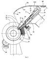
- фиг. 2, на которой представлен вид справа на станок в соответствии с предлагаемым изобретением, показанный на фиг.1;
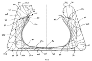
- фиг.3, на которой представлена эскизная схема в проекции на радиальную плоскость вида, который принимает кордная нить в следующие друг за другом моменты процесса ее укладки на основание способом в соответствии с предлагаемым изобретением;
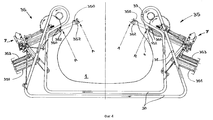
- фиг.4, на которой представлен общий вид основных элементов устройства укладки кордной нити;
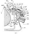
- фиг.5, на которой в увеличенном виде представлена правая часть изображения, показанного на фиг.4;
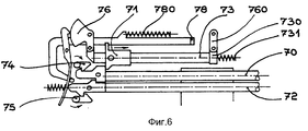
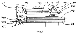
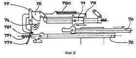
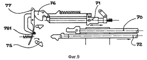
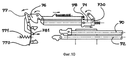
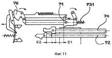
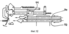
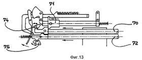
- фиг. с 6 по 13, на которых представлены последовательные стадии процесса функционирования прижимных устройств, используемых в конструкции станка в соответствии с предлагаемым изобретением;
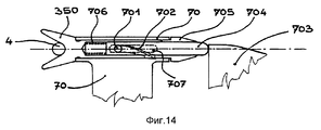
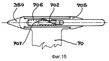
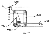
- фиг. с 14 по 17, на которых показаны составные элементы прижимных устройств в следующие друг за другом моменты функционирования этих устройств в составе станка в соответствии с предлагаемым изобретением;
- фиг. 18, которая иллюстрирует процесс регулировки устройства укладки кордной нити на основание;
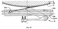
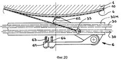
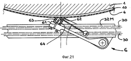
- фиг. с 19 по 21, иллюстрирующие конечную фазу изготовления данного силового элемента покрышки пневматической шины;
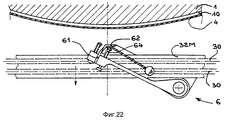
- фиг. 22, на которой показан способ закрепления нити после завершения изготовления данного силового элемента в процессе удаления технологического основания;
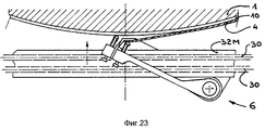
- фиг. 23, на которой показана начальная фаза изготовления силового элемента покрышки пневматической шины;
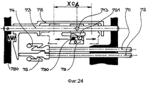
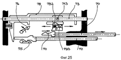
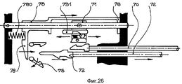
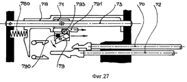
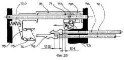
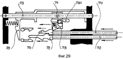
- фиг. с 24 по 29, на которых представлены последовательные стадии управления прижимными устройствами в соответствии с еще одним возможным вариантом их практической реализации.The following description makes it possible to explain in detail all the main aspects of the invention, based on the drawings, among which
- figure 1, which shows a view in frontal view of the machine in accordance with the invention;
- FIG. 2, which shows a right view of the machine in accordance with the invention, shown in figure 1;
- figure 3, which shows a preliminary diagram in projection onto the radial plane of the view that takes the cord at successive moments of the process of laying on the base by the method in accordance with the invention;
- figure 4, which shows a General view of the main elements of the device for laying cord cord;
- figure 5, in which an enlarged view shows the right side of the image shown in figure 4;
- FIG. 6 to 13, which show successive stages of the operation of the clamping devices used in the design of the machine in accordance with the invention;
- FIG. from 14 to 17, which shows the constituent elements of the clamping devices at successive moments of the functioning of these devices in the machine in accordance with the invention;
- FIG. 18, which illustrates the process of adjusting the device for laying the cord on the base;
- FIG. from 19 to 21, illustrating the final phase of the manufacture of a given pneumatic tire tire power element;
- FIG. 22, which shows a method of securing the thread after completion of the manufacture of a given power element in the process of removing the technological base;
- FIG. 23, which shows the initial phase of manufacture of a pneumatic tire tire strength member;
- FIG. from 24 to 29, which presents successive stages of control of the clamping devices in accordance with another possible option for their practical implementation.
На приведенных к данному описанию фиг.1 и 2 видно, что технологическое основание представляет собой жесткий и демонтируемый сердечник 1, определяющий собой геометрию внутренней поверхности покрышки пневматической шины. Этот сердечник 1 покрыт слоем герметизирующей резины на основе бутилового каучука и слоем каландрированной резины, предназначенным для закрепления кордной нити на поверхности сердечника приклеиванием. Сердечник 1 устанавливается на специальной консоли станины 2 и приводится во вращательное движение двигателем 20. Figures 1 and 2 given to this description show that the technological base is a rigid and
Устройство 3 укладки нити 4 содержит роликовую цепь 30, выполняющую здесь роль гибкого бесконечного приводного органа. Цепь 30 смонтирована на опорных роликах 31, которые устанавливаются на подвижном основании 32. Выполненное таким образом взаимное расположение элементов устройства укладки нити образует в совокупности направляющий контур станка. Траектория, которую описывает в своем движении цепь 30, имеет вид, напоминающий по форме букву C. Эта траектория содержит среднюю часть 32M и две боковые части 32L, шарнирно соединенные с упомянутой выше средней частью 32М, как будет более подробно описано ниже при помощи фиг.14. Пространственная фигура, которую образует описываемая цепью траектория, напоминает зажим или клещи, величина раскрытия которых может регулироваться в определенных пределах. Этот зажим может быть приспособлен к достаточно большому диапазону ширины упомянутого выше сердечника 1 и может раскрываться достаточно широко для того, чтобы пропустить наиболее широкую часть этого сердечника 1. The
Средняя часть 32М подвижного основания 32 установлена на приспособлении 5 выставки и регулировки положения устройства укладки нити 3 по отношению к сердечнику 1. Это приспособление содержит направляющий рельс 50, жестко закрепленный на станине 2 и ориентированный таким образом, чтобы направляющий контур располагался в радиальной плоскости. На упомянутом выше рельсе закреплена и может скользить вдоль него рама 51. Движение этой рамы по рельсу осуществляется при помощи винтового подъемника 52, приводимого в действие специальным двигателем 520. The
Кордная нить 4 снимается с бобины (на представленных фигурах эта бобина не показана) через специальное натяжное устройство или компенсатор натяжения нити 55, обеспечивающее требуемую величину натяжения нити в процессе ее укладки. Затем эта нить проходит через кольца 53 поводка 54, гибкость которого обеспечивает необходимую компенсацию движения нити между устройством укладки нити 3, которое тянет нить с циклически переменной скоростью, которая в отдельные моменты технологического цикла может быть даже отрицательной, и предшествующим ему натяжным устройством или компенсатором натяжения нити, которое не допускает обратного движения нити в сторону питающей бобины. Стержень отклонения 37 препятствует тому, чтобы нить 4 преждевременно входила в механический контакт с сердечником 1. Далее нить 4 пропускается через ушко 33 направляющего органа, которое установлено на цепи 30 с возможностью свободно поворачиваться. Цепь 30 приводится в движение двигателем 34. При этом ушко 33 совершает вместе с цепью возвратно-поступательное движение от одного борта изготавливаемой покрышки до другого или, точнее, от одной точки пространства, расположенной рядом с одним бортом этой покрышки, до другой точки пространства, располагающейся рядом с другим бортом той же самой покрышки. The
Направляющий рельс 50 закреплен на станине 2 таким образом, чтобы ушко 33 совершало свое возвратно-поступательное движение вокруг сердечника и над ним в радиальной плоскости; этот способ движения направляющего органа позволяет укладывать кордную нить 4 на сердечник таким образом, что в результате получается радиальный силовой каркас покрышки. При этом кордная нить образует радиальные дуги 40 на сердечнике 1, как видно из фиг.2. Стрелка F на этой фигуре показывает направление вращения сердечника 1. The
Описываемый здесь станок спроектирован специально для изготовления радиального силового каркаса покрышки пневматической шины и не приспособлен для выполнения других функций. Однако, само собой разумеется, что предлагаемое изобретение не ограничивается одним этим вариантом его практического применения. Так, например, для формирования плоскости укладки кордной нити, наклоненной по отношению к оси, в частности, для изготовления силового элемента вершины покрышки или брекера, достаточно предусмотреть в конструкции упомянутого выше станка дополнительную степень свободы для обеспечения возможности вращения рельса 50 вокруг радиально ориентированной оси, проходящей через середину сердечника 1, что позволяет ориентировать подвижное основание 32 по отношению к сердечнику 1. The machine described here is designed specifically for the manufacture of a radial power casing of a pneumatic tire tire and is not suitable for other functions. However, it goes without saying that the present invention is not limited to this one option for its practical application. So, for example, in order to form a laying plane of the cord thread, inclined with respect to the axis, in particular, for manufacturing the power element of the top of the tire or belt, it is sufficient to provide an additional degree of freedom in the design of the above-mentioned machine to enable the
Можно также предусмотреть весьма простой способ раскрытия образованного цепью 30 направляющего контура до величины, достаточной для того, чтобы, устанавливая ее в соответствии с типовым углом для изготовления силового элемента вершины покрышки (например, от 15 до 25o), возвратно-поступательное движение ушка 33 переводило его от одной боковины покрышки к другой над поверхностью сердечника 1, обеспечивая таким образом возможность укладки дуг кордной нити, образующих силовой пояс или брекер радиальной покрышки.You can also provide a very simple way of opening formed by the
Для изготовления силового каркаса диагональной покрышки с перекрещивающимися в различных слоях кордными нитями или для небольшого отхода от чисто радиальной ориентации можно предусмотреть возможность наклонения подвижного основания 32 по отношению к радиальной плоскости, поворачивая его вокруг оси, параллельной оси вращения сердечника. Разумеется, нет никаких препятствий и для того, чтобы комбинировать эту регулировку с другими описанными выше возможностями совершенствования станка в соответствии с предлагаемым изобретением. Это может понадобиться, в частности, для изготовления диагонального силового каркаса покрышки с перекрещивающимися в разных слоях этого каркаса нитями корда. Кроме того, ничего не меняя в конструкции и расположении описанных выше узлов и деталей этого станка, можно привести сердечник во вращательное движение с достаточно большой скоростью, составляющей, например, 1/8 оборота сердечника вокруг своей оси на 1/2 оборота цепи 30 по периметру направляющего контура таким образом, чтобы обеспечить получение угла укладки нити 4, который является функцией отношения скоростей движения цепи 30 и сердечника 1. Итак, становится ясно, что данный станок позволяет в случае необходимости ввести параметры вращательного движения сердечника в совокупность параметров, определяющих характеристики процесса укладки кордной нити. For the manufacture of a power frame of a diagonal tire with cord threads intersecting in different layers or for a slight departure from a purely radial orientation, it is possible to tilt the
Фиг. 3, на которой подробно поясняются детали и особенности основного движения направляющего органа станка, позволяет четко уяснить то, каким образом осуществляется укладка нити 4 на поверхность сердечника 1. Отметил прежде всего, что сердечник, на который в процессе изготовления силового каркаса покрышки пневматической шины укладывается кордная нить, предварительно покрывается одним или несколькими необходимыми в данном случае слоями каучука 10, а также в случае необходимости одним или несколькими слоями других подкрепляющих нитей, которые могут понадобиться, в частности, в зонах формирования бортов покрышки. На фиг. 3 обозначены опорные ролики 31, на которых смонтирована роликовая цепь 30. Стрелка на каждом опорном ролике 31 на фиг.3 указывает направление его вращения. Предположим сначала, что нить 4 удерживается прижатой к сердечнику 1 в произвольно выбранном месте своей желательной траектории, расположенной в изготавливаемой покрышке, например, в средней точке S вершины сердечника 1. При этом предполагается, что ушко 33 находится в положении, обозначенном позицией 33a и удаляется от упомянутой выше точки S в направлении, указанном стрелкой M. Нить 4 располагается в этом состоянии так, как показано пунктиром 41a. FIG. 3, which explains in detail the details and features of the main movement of the guide body of the machine, it makes it possible to clearly understand how the
Продолжение движения ушка 33 вместе с цепью направляющего контра по стрелке M вызывает скольжение нити 4 внутри этого ушка и приводит к вытягиванию нити 4 с питающей бобины, поскольку эта нить первоначально подается в среднюю плоскость сердечника 1 с помощью гибкого поводка 54, что проиллюстрировано, в частности, на фиг.2. Дальнейшая последовательность положений, занимаемых движущимся ушком 33, обозначена на фиг.3 позициями 33b, 33c. ..33k. Последовательные положения, которые занимает при этом нить 4, изображены на фиг. 3 двумя семействами кривых. Первое семейство кривых на этом рисунке показано пунктирными линиями, а второе показано сплошными линиями. Переходя от точки 33a к точке 33b, можно заметить, что в этом новом положении ушка 33 уже отсутствует возможность соединить это новое положение с точкой S прямой линией, поскольку такая линия, проведенная на чертеже, начинает пересекать контур сердечника 1. Таким образом, при перемещении ушка 33 в положение, обозначенное позицией 33b, нить 4 начинает наматываться на верхнюю часть сердечника 1. Когда ушко 33 в процессе своего движения перемещается в положение, обозначенное позицией 33c, одно из упомянутых выше прижимных устройств 35, располагающихся на каждом из концов направляющего контура, захватывает нить 4 и прижимает ее к поверхности упомянутого выше сердечника в точке В1. Первое из упомянутых выше семейств кривых завершается кривой 41c, соединяющей точку 33c с серединой верхней части сердечника 1, обозначенной позицией S. Continuing the movement of the
Упомянутые выше прижимные устройства 35 в конструкции станка в соответствии с предлагаемым изобретением отрегулированы таким образом, чтобы вступать в действие только после того, как направляющее ушко 33 подведет нить 4 к соответствующему концу направляющего контура и упомянутая нить расположится между рабочим органом соответствующего прижимного устройства и поверхностью сердечника 1. The
Начиная с точки В1 по ходу движения ушка 33 по траектории направляющего контура последовательные положения, которые занимает ведомая этим ушком нить 4, изображены сплошными линиями, которые образуют второе из двух упомянутых выше семейств кривых. Первая из кривых этого семейства, обозначенная позицией 41d, соединяет точку В1 прижатия и приклеивания нити 4 к поверхности сердечника 1 с точкой 33d, обозначающей положение ушка 33 на одном из опорных роликов 31 (в данном случае это левый ролик по схеме направляющего контура, приведенной на фиг.4). На фиг.3 видно, что при переходе направляющего ушка из положения 33e в положение 33f, затем при его переходе из положения 33g в положение 33h, и еще раз, при переходе движущегося направляющего ушка из положения 33j в положение 33k, расстояние между последней точкой (В1), где нить 4 была приклеена к поверхности сердечника 1, и ушком 33 уменьшается, то есть сокращается длина соединяющей их нити. Именно поэтому система подачи нити 4 в устройство ее укладки 3 должна быть способна как бы поглощать нить в отдельные моменты технологического цикла и вообще должна быть способна поддерживать определенный уровень натяжения нити 4, несмотря на весьма значительные флюктуации потребности в этой нити со стороны устройства укладки 3. Семейство кривых, обозначенных позициями 41d...41i, позволяет наглядно увидеть, как нить 4 постепенно укладывается на сердечник 1. В конечном счете, когда направляющее ушко 33 достигнет положения, обозначенного точкой 33k, другое прижимное устройство 35 вступает в действие с тем, чтобы прижать нить 4 к поверхности основания 1 в точке, обозначенной позицией В2, в зоне борта изготавливаемой покрышки. Starting from point B1 in the direction of the eye of the
На фиг. 4 и 5 видно, что каждое из прижимных устройств 35, предусмотренных в конструкции станка в соответствии с предлагаемым изобретением, содержит вилку 350, способную перемещаться в диапазоне между задним или убранным положением, обозначенным на упомянутых выше рисунках позицией R, в котором эта вилка удалена от поверхности сердечника 1, и передним или выдвинутым положением, обозначенным на этих рисунках позицией A. Положение A упомянутой выше вилки 350 представляет собой то пространственное положение, которое эта вилка займет при отсутствии сердечника 1. В это положение вилку 350 переводит пружина 351, которая давит на упомянутую выше вилку через рычаг 354 и тягу 355. В реальных условиях эксплуатации описываемого здесь станка перемещающаяся под действием пружины 351 вилка 350 фактически остановится раньше, войдя в механический контакт с теми компонентами изготавливаемой в данном случае покрышки, которые к этому моменту уже нанесены или уложены на поверхность сердечника 1. Это, во-первых, предварительное каучуковое покрытие поверхности сердечника, и, во-вторых, возможно, уложенные ранее слои кордной нити силового каркаса изготавливаемой покрышки. Таким образом, упомянутая выше вилка 350, если она захватила своими ветвями нить 4, позволяет прижать эту нить к поверхности сердечника с усилием, достаточным для полноценного приклеивания нити в нужном месте этой поверхности при наличии соответствующей адгезии в месте контакта. In FIG. 4 and 5 it is seen that each of the
Движение направляющего ушка 33 из положения, обозначенного точкой 33j, в положение, обозначенное точкой 33k, в соответствии со схемой, приведенной на фиг.3, позволяет ему зацепить или навесить нить 4 на вилку 350 в тот момент, когда эта вилка находится в заднем или убранном положении, обозначенном позицией R (см. также фиг.5). Отметим, что в этом заднем или убранном положении валка 350 ее ветви или зубцы располагаются в плоскости, перпендикулярной плоскости фиг.4 или плоскости фиг.5, что дает возможность надежно удерживать нить 4, которая подается на вилку 350 ушком 33. The movement of the
Затем в соответствующий момент технологического цикла работы описываемого здесь станка вилка 350 вместе с удерживаемой ею нитью 4 переходит из своего убранного положения в переднее или выдвинутое положение, обозначенное на фиг. 4 и 5 позицией A. В начальной стадии своего поступательного движения вперед на выдвижение вилки 350 одновременно с этим прямолинейным движением совершает поворот на четверть оборота вокруг своей продольной оси для того, чтобы ее ветви перешли в плоскость фиг.4 или плоскость фиг.5 перед вхождением этих ветвей в механический контакт с поверхностью сердечника 1. С каждой стороны сердечника 1 этот поворот вилки на четверть оборота переводит ветвь, которой вилка 350 зацепляет нить 4, в сторону наибольших радиусов сердечника 1. Then, at the appropriate time in the operation cycle of the machine described here, the
Исследуя схемы, приведенные на фиг.4 и 5, можно прийти к выводу о том, что нить 4 проводится над плоскостью упомянутых выше рисунков. Ветвь 350F вилок 350, которая в убранном положении R вилок выступает из плоскости упомянутых выше рисунков по направлению к наблюдателю. Другими словами, сторона, на которую зацепляется или навешивается нить 4, поворачивается в сторону наибольших радиусов сердечника 1 в процессе выдвижения вилки 350 в направлении показанного на рисунках положения A. Отметим также, что каждая дуга 40 нити 4, укладываемой данным станком, скрывается за плоскостью фиг.4, что определяет направление вращения сердечника 1. Examining the schemes shown in figures 4 and 5, we can conclude that the
В предпочтительном варианте практической реализации станка в соответствии с предлагаемым изобретением упомянутые выше прижимные устройства кроме перечисленных уже элементов содержат также молоточек 352, который содействует закреплению нити 4 в каучуковом слое на поверхности сердечника 1. Этот молоточек 352 также является подвижным и способен перемещаться из своего убранного положения, обозначенного на фиг.5 позицией R, в рабочее или выдвинутое положение, обозначенное позицией A. Это свое перемещение молоточек 352 совершает под действием пружины 353, давит на этот молоточек через рычаг 356 и тягу 357. Оба упомянутых выше рычага 354 и 356 имеют одну и ту же ось вращения 308. In a preferred embodiment of the practical implementation of the machine in accordance with the invention, the aforementioned pressing devices, in addition to the elements already listed, also comprise a
Молоточек 352 вступает в действие после срабатывания на выдвижение вилки 350. Он выдвигается в направлении сердечника 1 после того, как вилка 350 прижмет нить 4 к поверхности сердечника 1, и упирается в уложенную на поверхность сердечника 1 нить 4 в радиальном направлении несколько выше упомянутой вилки, если смотреть по ходу вдоль нити направляющего ушка 33. Прижав нить 4 к поверхности сердечника 1, молоточек 352 удерживает эту нить в таком состоянии в процессе отхода и уборки упомянутой выше вилки. Этим предотвращается унос вилкой при ее уборке петли нити 4, которая образуется вокруг одной из ее ветвей и которая, даже будучи приклеенной к каучуковому покрытию сердечника 1, может потянуться за вилкой и оторваться от поверхности сердечника. Закрепление нити 4 на поверхности сердечника 1 в зоне борта изготавливаемой покрышки при использовании упомянутого выше молоточка 352 оказывается, таким образом, весьма надежным. При этом достаточно, чтобы молоточек 352 возвратился в свое убранное положение во-время и был подготовлен для своего нового срабатывания на выдвижение при подводе к краю направляющего контура станка нового участка нити 4 направляющим ушком 33. The
В предпочтительном варианте практической реализации станка в соответствии с предлагаемым изобретением срабатывание и переход в выдвинутое состояние, а также переход в убранное состояние после выполнения своей функции, как для вилки 350, так и для молоточка 352, управляется штифтом 36, закрепленным на цепи 30 со стороны, противоположной стороне расположения на этой цепи направляющего ушка 33. По отношению к плоскости фиг.4 или фиг.5 направляющее ушко 33 располагается выше или над этой плоскостью со стороны подвода нити 4, а штифт 36 соответственно располагается ниже плоскости упомянутых рисунков или под ней. Там же, под плоскостью фиг.4 и фиг.5, располагаются механизмы 7 взведения и спуска, приводящие в действие выдвижные вилки 350 и молоточки 352. In a preferred embodiment of the practical implementation of the machine in accordance with the invention, the actuation and transition to the extended state, as well as transition to the retracted state after performing its function, both for the
Приведенные в приложении к данному описанию фигуры с 6 по 13 более подробно иллюстрируют устройство и конструкцию одного из этих механизмов, одинаковых с каждой стороны направляющего контура станка в соответствии с предлагаемым изобретением. Консультируясь параллельно со схемой, приведенной на фиг.5, можно легко понять, каким образом и в какой момент рабочего цикла эти механизмы взаимодействуют с цепью 30, движение которой задает ритм работы всего устройства 3 укладки нити 4, а также отчетливо представить себе, как эти механизмы приводят в движение вилки 350 и молоточки 352. The figures 6 to 13 given in the appendix to this description illustrate in more detail the structure and design of one of these mechanisms, which are the same on each side of the guide contour of the machine in accordance with the invention. Consulting in parallel with the circuit shown in Fig. 5, one can easily understand how and at what point in the work cycle these mechanisms interact with
На упомянутой выше группе рисунков виден хвостовик 70 вилки 350, а также хвостовик 72 молоточка 352. Кулиса 71 имеет возможность скользить вдоль стержня 73. Эта кулиса непрерывно совершает попеременное возвратно-поступательное движение вдоль упомянутого выше стержня 73 под действием шатуна 711 (см. фиг. 5), приводимого в движение пальцем 710, закрепленным на зубчатом колесе 712. Это зубчатое колесо приводится во вращательное движение роликом или звездочкой 31, огибаемым цепью на краю направляющего контура. In the above-mentioned group of figures, the
В положении, показанном на фиг. 6, хвостовики 70 и 72 удерживаются в фиксированном положении, блокирующем их поступательное движение, соответственно защелками 74 и 75. Упомянутый выше стержень 73 вместе с кулачком 76 и тягой 760 образуют шарнирный параллелограмм. Этот параллелограмм имеет возможность деформироваться так, как показано на фиг.7: подходя в процессе своего движения к концу стержня 73, кулиса 71 нажимает на выступ 730, преодолевая сопротивление противодействующей такому движению пружины 731. В результате деформации упомянутого выше шарнирного параллелограмма кулачок 76 поворачивается, что позволяет стопору 77 также повернуться и зафиксировать достигнутое угловое положение кулачка. Эта операция завершает процесс взведения механизма. Далее, вплоть до момента включения в работу штифта 36, механизм остается во взведенном состоянии. Он остается в этом состоянии даже тогда, когда кулиса 71, продолжая свое попеременное возвратно-поступательное движение, каждый раз воздействует на спусковой механизм 78, который при этом отходит назад, преодолевая сопротивление пружины 780 и заставляя также отходить назад собачку 781. In the position shown in FIG. 6, the
Задняя лапа 770 стопора 77, которая будет стремиться сдвинуться вправо (см. фиг. 7) под действием пружины 771, удерживается тем не менее в заблокированном положении собачкой 781 и хвостовиком 72 молоточка, которые действуют в этом смысле параллельно и совместно. До тех пор, пока собачка 781 и хвостовик 72 молоточка не окажутся оба вместе сдвинутыми вправо в один и тот же момент времени, задняя лапа 770 стопора будет оставаться неподвижной, и стопор 77 будет препятствовать повороту кулачка 76. The
На фиг. 5 показано положение 36a, достигая которого в процессе движения цепи штифт 36 вызывает срабатывание механизма выдвижения вилки 350. При помощи промежуточной передачи, состоящей из двух угловых качалок 741 и 742, а также тяги 740 защелка 74 поднимается (см. фиг.5 и 8), в результате чего освобождается хвостовик 70 вилки 350. После этого под действием пружины 351 вилка 350 и хвостовик 70 этой вилки тотчас же смещаются вправо, как показано на фиг. 8, в направлении выдвинутого положения A, показанному на фиг.4. Поскольку в этот момент стопор 77 еще не разблокировал кулачок 76, это поступательное движение может осуществляться без зацепления хвостовика 70 и кулисы 71. Поэтому попеременное возвратно-поступательное движение кулисы 71 продолжается свободно. In FIG. 5 shows the
В тот момент, когда упомянутый выше штифт 36 достигает положения 36b, обозначенного на фиг.5, защелка 75 при помощи другой промежуточной передачи, состоящей из тяги 750 и угловой качалки 751, освобождает хвостовик 72 (см. фиг.5 и 9). После этого под действием пружины 353 молоточек 352 и его хвостовик 72 тотчас же смещаются вправо, как показано на фиг.9, в направлении выдвинутого положения A, показанного на фиг.4. Отметим здесь, что после этого стопор 77 продолжает удерживаться в своем блокирующем кулачок 76 положении уже только собачкой 781. At the moment when the
Теперь, как только кулиса 71 в процессе своего попеременного возвратно-поступательного движения по стержню 73 упрется в выступ 730 и нажмет на рычаг спускового механизма 78 (см. фиг.10), собачка 781 освободит стопор, точнее, отведет его в сторону от кулачка 76, и этот освобожденный уже кулачок под действием пружины 731 повернется по часовой стрелке, как показано на фиг. 11. В своем обратном движении кулиса 71 увлекает за собой хвостовики 70 и 72 в положение, соответствующее состоянию взведения механизма (смотри фиг. 12), где эти хвостовики блокируются защелками 74 и 75 описанным уже выше образом (см. фиг. 13). Далее блокировка механизма происходит так, как было описано выше. Now, as soon as the
Расстояния E1 и E2 между положениями хвостовиков 70 и 72 и кулисы 71, хорошо видимые на фиг.11, позволяют гарантировать, что молоточек 352 всегда будет достигать своего выдвинутого положения прежде, чем начнется его обратное движение в процессе взведения механизма, и что при повторном возведении этого механизма вилка 350 будет возвращаться в свое исходное положение или убранное положение раньше или впереди молоточка 352. The distances E1 and E2 between the positions of the
В качестве возможного варианта конструкции описанного выше механизма кулиса 27 может содержать штифт 79, предназначенный для того, чтобы интегрировать функцию, обеспечиваемую в предыдущем варианте конструкции этого механизма деформацией упомянутого там параллелограмма, позволяющей взвести и подготовить к выполнению рабочего хода описанные выше вилки и молоточки. На фиг. 24 и последующих рисунках можно видеть, что стержень 73, по которому может скользить кулиса 71, на этот раз выполнен неподвижным. Как и в описанном выше варианте конструкции данного механизма, здесь кулиса 71 приводится в движение шатуном 711, который виден на фиг.5. Головка этого шатуна соединена шарнирно с точкой 713 на кулисе. Под действием пружины 790 штифт 79 стремится занять развернутое вокруг точки его крепления положения положение, показанное на фиг.27. Толкатель 791 имеет возможность скользить в упомянутой выше кулисе 71 и занимать либо положение, показанное на фиг.27, либо положение, показанное на фиг.24. Этот толкатель 791 содержит вырез 792, в который может западать шарик 793. Спусковой механизм 78 в этом варианте конструкции выполнен скользящим по стержню 73. Поэтому он естественным образом занимает под действием пружины 780 положение, показанное на фиг.26. As a possible design option, the link mechanism 27 described above may include a
Спуск взведенного механизма в данном варианте конструкции и выдвижение в рабочее положение вилки и молоточка управляются защелками 74 и 75 так же, как это происходит и было описано в предыдущем варианте конструкции. В момент повторного спуска механизм находится в состоянии, показанном на фиг.26. Затем, как только кулиса 71 достигнет левой мертвой точки (это положение показано на фиг. 27), спусковой механизм 78 нажимает на толкатель 791 с тем, чтобы вырез 792 был подведен к шарику 793 и принял его в свою полость. Это позволяет штифту 79 развернуться на некоторый угол. Теперь при последующем смещении кулисы 71 штифт 79 пройдет над хвостовиком 70 вилки 350 в механическом контакте с ним, но без влияния на его собственное движение и положение, после чего снова развернется в прежнее положение. Затем, когда кулиса 71 дойдет по правой мертвой точки и начнет свое обратное движение (см. фиг. 28), штифт 79 упрется в хвостовик 70 вилки и поведет его, а вместе с ним и хвостовик 72 молоточка, в направлении их убранного или взведенного положения (см. фиг. 29), что приведет также к перемещению спускового устройства 78, сжимающего противодействующую пружину 780. Затем в процессе дальнейшего движения кулисы 71 толкатель 791 упирается в другую сторону спускового механизма 78, в результате чего скользит в упомянутой выше кулисе. Шарик 793 при этом выталкивается из полости выреза 792 соседствующей с этим вырезом наклонной поверхностью и нажимает на штифт 79. Этот штифт убирается внутрь кулисы 71 (см. фиг.23), которая после этого может беспрепятственно продолжать свое возвратно-поступательное движение, не встречая на своем пути хвостовик 70 вилки 350 до следующего повторения описанного выше рабочего цикла механизма выпуска и уборки вилок и молоточков. The descent of the cocked mechanism in this embodiment and the extension to the working position of the fork and hammer are controlled by
Способ практического осуществления упомянутого выше поворота вилки 350 на четверть оборота вокруг собственной продольной оси в процессе ее выдвижения в рабочее положение проиллюстрирован на фиг.14 и 15. Вилка 350 устанавливается с возможностью поворота в подшипнике, реализованном на переднем конце хвостовика 70. Этот поворот вилки на четверть оборота контролируется выступом 701 толкателя 704. Выступ 701 вставляется в вырез 702 спиральной фермы, выполненный внутри гильзы 705, продолжающей вилку 350 в ее задней части, и вставлен также в прямолинейный вырез 707, выполненный в подшипнике, установленном на переднем конце хвостовика 70. Толкатель 704 задвигается внутрь вилки 350 в том случае, когда он наталкивается на упор 703. Это происходит при перемещении вилки 350 в свое убранное положение R (см. фиг.14). Как только вилка 350 начинает перемещаться в свое выпущенное или выдвинутое положение, отводя толкатель 704 от упомянутого выше упора, под действием пружины 706 упомянутый толкатель возвращается в свое исходное положение (см. фиг. 15). Введение толкателя 704 в гильзу 705 позволяет выступу 701 воздействовать на вырез 702, что вызывает ее поворот вокруг продольной оси на четверть оборота. A method for practical implementation of the aforementioned rotation of the
В процессе перехода направляющего ушка 33 из положения 33i (см. фиг.3) в положение 33k нить 4 проходит над упором 703, а затем и над одной из ветвей вилки 350, слегка отклоняясь от плоскости (перпендикулярной плоскости фиг.14 и обозначенной на нем своим следом в виде оси вилки), в которой эта нить натянута (между последней точкой, где она уже приклеена к поверхности сердечника 1, и ушком 33), благодаря хорошо видимым на фиг.14 наклонным поверхностям, которые позволяют избежать нежелательного зацепления нити 4 за элементы задней части вилки 350. During the transition of the
На фиг. 16 можно видеть, что молоточек 352 смонтирован на своем хвостовике 72 при помощи двух параллельных друг другу тяг 721 и 722, На одну из этих тяг (тяга 722 на фиг.16) воздействует спиральная крутящая пружина 723, которая своим усилием стремится повернуть упомянутые выше тяги по часовой стрелке, как показано на фиг.16. Упор 724, выполненный заодно с тягой 722, входит в контакт с хвостовиком 72, когда молоточек 352 находится в поднятом положении (см. фиг. 17). Когда молоточек 352 возвращается в свое нерабочее или убранное положение, обозначенное позицией R, он встречает на своем пути упор 725, который заставляет описание выше конструкцию в определенной степени складываться (см. фиг.16), благодаря чему она не препятствует перемещениям нити 4 при движении ушка 33 по траектории направляющего контура станка. Осевая штрих-пунктирная линия на фиг. 16 и 17 представляет собой след плоскости, в которой проходит нить 4. Как только молоточек 352 сошел с упора 725, то есть как только началось его перемещение на выдвижение, он поднимается для того, чтобы иметь возможность надлежащим образом воздействовать на нить 4, которая в этот момент точно подведена к поверхности сердечника 1 вилкой 350. Движение молоточка 352 описывает плоскость, представленную своим следом, обозначенным в виде штрих-пунктирной осевой линии на фиг.17. In FIG. 16 you can see that the
Принцип намотки нити на технологическое основание, примененный в конструкции станка в соответствии с предлагаемым изобретением, предполагает, что это технологическое основание или сердечник являются выпуклыми или по меньшей мере обладают лишь незначительными по протяженности и глубине вогнутыми участками, такими, например, как зона обычной автомобильной покрышки между бортом и боковиной. Однако некоторые типы покрышек пневматических шин обладают значительной по величине центральной впадиной, как это видно, например, из американского патента US 3830273. Для того, чтобы станок в соответствии с предлагаемым изобретением был способен воспринять технологические основания или сердечники со значительными по протяженности и глубине участками вогнутости, достаточно добавить напротив этих вогнутостей одно или несколько дополнительных прижимных устройств, позволяющих надлежащим образом уложить кордную нить на поверхность этих вогнутых участков покрышки. Эти дополнительные прижимные устройства должны вступать в работу в нужный момент в точном соответствии с принципами, изложенными выше для прижимных устройств 35. И располагаются эти дополнительные прижимные устройства уже не на краях направляющего контура, то есть на концах трассы дуги из кордной нити, а в некоторых промежуточных положениях, соответствующих положению вогнутых зон на данном технологическом основании. Такое прижимное устройство имеет в своем составе молоточек 352, поскольку вилка 350 в данном случае является излишней в той мере, в какой траектория укладываемой нити 4 остается вписываемой в ту же самую плоскость по одну и по другую сторону от участка нити 4, на которую воздействует данное прижимное устройство. The principle of winding the thread onto a technological base used in the design of the machine in accordance with the invention assumes that this technological base or core is convex or at least have only concave sections that are insignificant in length and depth, such as, for example, the area of a common car tire between the side and the sidewall. However, some types of pneumatic tire tires have a large central depression, as can be seen, for example, from US Pat. No. 3,830,273. In order for the machine in accordance with the invention to be able to perceive technological bases or cores with concavity sections that are significant in length and depth , it is enough to add one or several additional clamping devices opposite these concavities, allowing to properly lay the cord thread on the surface of these mentioned tire sites. These additional pressure devices must come into operation at the right time in strict accordance with the principles set forth above for
Принцип раскрытия направляющего контура станка в соответствии с предлагаемым изобретением объясняется при помощи схемы, приведенной на фиг.18. Ширина средней части 32M основания 32 предполагается известной. Боковые части 32L направляющего контура станка шарнирно связаны с его средней частью 32M. Перемещение этих боковых частей 32L направляющего контура с целью увеличения или уменьшения раскрытия этого контура осуществляется при помощи перемещения ползуна 320, воздействующего симметричным образом на боковые части упомянутого выше направляющего контура через регулируемые по длине тяги 322. Для того, чтобы цепь 30 имела возможность при изменении угла раскрытия направляющего контура проходить в своем движении неизменное расстояние, то есть для избежания необходимости изменения длины цепи при изменении угла раскрытия этого направляющего контура, можно либо соответствующим образом выбрать точки шарнирного соединения боковых частей упомянутого направляющего контура с его средней частью, либо предусмотреть в конструкции этого направляющего контура дополнительные натяжные ролики (эти ролики не показаны на приведенном в приложении к данному описанию рисунке 18 с тем, чтобы не загромождать его) или передать эту роль дополнительного натяжения цепи 30 направляющего контура одному из уже имеющихся в конструкции направляющих роликов 31. The principle of disclosure of the guide contour of the machine in accordance with the invention is explained using the circuit shown in Fig. The width of the
Изготовление силового каркаса покрышки пневматической шины или отдельных силовых элементов этой покрышки предполагает соответствующую координацию вращательного движения сердечника 1 и поступательного движения цепи 30 путем надлежащего управления вращением двигателей 20 и 34. За один полный оборот по направляющему контуру цепи 30 сердечник 1 должен повернуться на весьма небольшой угол, соответствующий удвоенному шагу укладки нити P, желательному в данном случае для данной нити 4, поскольку направляющее ушко 33 за один полный оборот по направляющему контуру укладывает две дуги 40 кордной нити 4. В наиболее простом варианте практической реализации конструкции станка в соответствии с предлагаемым изобретением отношение скоростей движения сердечника 1 и цепи 30 является постоянной величиной. Однако для изготовления радиального силового каркаса покрышки желательно располагать последовательно уложенными дугами 40 кордной нити (см. фиг.2) в радиальной плоскости. Для осуществления такого условия необходимо, чтобы сердечник 1 поворачивался скачкообразно. Это означает, что поворот на соответствующий угол, определяемый требуемым шагом укладки кордной нити, должен осуществляться в тот момент, когда прижимные устройства 35 удерживают нить 4 прижатой к поверхности сердечника 1, а затем на протяжении всего периода укладки очередной радиальной дуги кордной нити сердечник 1 должен оставаться неподвижным. The manufacture of the power casing of a pneumatic tire tire or of the individual power elements of this tire involves the appropriate coordination of the rotational motion of the
Для того, чтобы упростить управление движением различных элементом статика и сохранить неизменным, то есть равномерным, движение сердечника 1, данное изобретение предлагает паллиативное решение: ролики 31A и 31B, располагающиеся по обе стороны от средней части направляющего контура 32M и поддерживающие цепь 30 на траектории ее прямого движения, а также ролики 31C и 31D, располагающиеся также по обе стороны средней части 32M направляющего контура, но поддерживающие эту же цепь 30 на траектории ее обратного движения, слегка наклоняются в окружном направлении (принимая за точку отсчета сердечник 1) для того, чтобы, учитывая относительное вращательное движение между направляющим ушком 33 и сердечником 1, в процессе которого ушко 33 проходит от одной до другой стороны сердечника 1, кордная нить 4 была уложена на вершину сердечника 1 строго в теоретической плоскости, содержащей желаемую траекторию нити 4 на поверхности сердечника 1 в каждом из двух направлений осевого движения направляющего ушка 33 относительно сердечника 1. Таким образом, при реализации описанной выше схемы кордные нити 4 будут располагаться практически идеальными радиально ориентированными дугами 40 на поверхности сердечника 1. In order to simplify the control of the movement of various static elements and to keep the
В зоне кривизны обратного знака на сердечнике 1, соответствующей началу боковин покрышки сразу за конструкцией борта, необходимо еще довершить приклеивание нити 4 к поверхности сердечника 1. При этом на практике нет необходимости для этого делать что-либо специально. Опыт показывает, что последующее наложение слоя каландрированного каучука или любого другого компонента данной покрышки поверх уложенного слоя кордной нити в процессе ее дальнейшего изготовления оказывается вполне достаточным для осадки и доклейки этого слоя к подлежащей поверхности покрышки. In the zone of curvature of the opposite sign on the
Приведенные в приложении к данному описанию фигуры с 19 по 23 иллюстрируют конструкцию органа 6, который позволяет автоматизировать запуск и остановку процесса изготовления силового каркаса покрышки пневматической шины. Этот орган 6 закрепляется на средней части основания 32, откуда он может быть легко удален, когда в нем нет необходимости, для того, чтобы не мешать укладке нити 4 (см. фиг.19). Этот орган содержит нож 61, противоположное лезвие 62 и два пальца 63 и 64. The figures 19 to 23 given in the appendix to this description illustrate the design of the
В конце процесса изготовления силового каркаса покрышки пневматической шины (см. фиг.20) направляющее ушко 33 останавливается точно после преодоления средней плоскости сердечника 1 при своем проходе этой зоны слева направо. При этом орган 6 поднимается, нож 61 выдвигается в направлении сердечника 1 (см. фиг.21), что приводит к перерезанию нити 4 между ножом 61 и противоположным лезвием 62. Палец 63 прижимает конец нити 4 к поверхности сердечника, палец 64 удерживает нить 4 на противоположном лезвии 62. Устройство укладки нити 3 при этом может открыться, рама 51 скользит по рельсу 50, что полностью освобождает сердечник 1, на котором осуществляется изготовление силового каркаса покрышки (см. фиг.22). At the end of the manufacturing process of the power frame of the tire of the pneumatic tire (see Fig. 20), the
В момент начала изготовления следующего силового каркаса устройство укладки нити 3 приближается к новому сердечнику 1 (см. фиг.23), после чего начинается движение ушка 33 по траектории направляющего контура. Как только это ушко 33 обогнет сердечник, начало нити 4 оказывается приклеенным к поверхности сердечника 1, предварительно покрытой слоем каучука. At the time of starting the manufacture of the next power cage, the yarn-laying
Предлагаемый способ изготовления радиального силового каркаса покрышки пневматической шины может быть осуществлен в различных вариантах для реализации одного слоя каркаса или нескольких его слоев. Можно изготовить один слой силового каркаса из нескольких проходов (n) укладки нити, каждый из которых покрывает весь сердечник 1. В этом случае внутренние дуги одного прохода укладываются с шагом P, и положение нитей 4 на сердечнике 1, укладываемых в процессе двух последовательных проходов, образует сдвиг в окружном направлении на расстояние, соответствующее величине P/n. Специалист в области шинного производства может без затруднений предусмотреть многочисленные варианты практического использования предлагаемого изобретения в соответствии с конкретной "архитектурой" покрышки пневматической шины, которую он хочет получить. The proposed method of manufacturing a radial power casing of a tire of a pneumatic tire can be carried out in various ways to implement one layer of the carcass or several layers thereof. It is possible to make one layer of the power frame from several passages (n) of laying the threads, each of which covers the
Область возможного использования предлагаемого изобретения не ограничивается различными механическими органами описанного выше станка. Специалист в своем деле сможет без особенного труда создать различные эквиваленты описанных выше элементов предлагаемого станка, например системы взведения и срабатывания, или применить соответствующим образом изогнутый рельс вместо опорных роликов для материализации направляющего контура. The scope of the possible use of the invention is not limited to various mechanical organs of the machine described above. The specialist in his business will be able to easily create various equivalents of the above-described elements of the proposed machine, for example, a cocking and triggering system, or use a suitably curved rail instead of support rollers to materialize the guide contour.
Claims (16)
последним перемещения по дугообразной траектории, что приводит к их относительному смещению за один цикл намотки на величину, соответствующую шагу укладки кордной нити на поверхность основания таким образом, что нить образует на этой поверхности примыкающие друг к другу радиальные дуги.1. A method of manufacturing a rubber tire of a pneumatic tire, comprising applying to the base, the surface of which is in the form of the inner surface of the tire being manufactured, of various components on the places provided for by the construction of the tire, the cord laid on the base is attached to it by gluing, characterized the fact that the formation of the tire is carried out by one continuous cord thread, fixed at some starting point on the base and laid on the latter by means of a guiding organ sliding along this thread, which is moved in a transverse plane along an arc-shaped trajectory around the base and above it from the starting point to some end point of the arc-shaped path in which the thread changes its direction, and then to another end point corresponding to another edge of the same arc-shaped trajectory, as a result of which the cord thread passes from one side of the base to the other and vice versa, which leads to the cord being wrapped around the base, and at each end point of the arcuate the sectors press and / or glue the cord to the base, in addition, carry out a relative circular movement of the base and the guide body while maintaining
the latter moves along an arcuate trajectory, which leads to their relative displacement in one winding cycle by an amount corresponding to the step of laying the cord thread on the base surface so that the thread forms radial arcs adjacent to each other on this surface.
Applications Claiming Priority (2)
| Application Number | Priority Date | Filing Date | Title |
|---|---|---|---|
| FR9209256 | 1992-07-21 | ||
| FR9209256 | 1992-07-21 |
Publications (2)
| Publication Number | Publication Date |
|---|---|
| RU93036961A RU93036961A (en) | 1996-06-27 |
| RU2139192C1 true RU2139192C1 (en) | 1999-10-10 |
Family
ID=9432304
Family Applications (1)
| Application Number | Title | Priority Date | Filing Date |
|---|---|---|---|
| RU93036961/12A RU2139192C1 (en) | 1992-07-21 | 1993-07-20 | Method of and machine for building cautochouc pneumatic tyre |
Country Status (15)
| Country | Link |
|---|---|
| US (2) | US5453140A (en) |
| EP (1) | EP0580055B1 (en) |
| JP (1) | JP3237967B2 (en) |
| KR (1) | KR100289757B1 (en) |
| CN (1) | CN1047555C (en) |
| AT (1) | ATE148028T1 (en) |
| BR (1) | BR9302937A (en) |
| CA (1) | CA2101001C (en) |
| CZ (1) | CZ290253B6 (en) |
| DE (1) | DE69307614T2 (en) |
| ES (1) | ES2099324T3 (en) |
| MX (1) | MX9304347A (en) |
| PL (1) | PL171584B1 (en) |
| RU (1) | RU2139192C1 (en) |
| TW (1) | TW223038B (en) |
Cited By (1)
| Publication number | Priority date | Publication date | Assignee | Title |
|---|---|---|---|---|
| RU2606647C2 (en) * | 2012-06-20 | 2017-01-10 | Фудзи Сейко Ко., Лтд. | Device for bead ring bonding thread winding |
Families Citing this family (45)
| Publication number | Priority date | Publication date | Assignee | Title |
|---|---|---|---|---|
| FR2804367B1 (en) * | 2000-02-01 | 2002-09-20 | Sedepro | OSCILLATING ARM APPARATUS FOR MANUFACTURING A TIRE REINFORCEMENT FROM A SINGLE THREAD |
| IT1281088B1 (en) * | 1995-12-19 | 1998-02-11 | Bridgestone Firestone Tech | WINDING UNIT FOR THE REALIZATION OF A TOROIDAL HOUSING FOR A ROAD VEHICLE TIRE. |
| US6318432B1 (en) | 1997-11-28 | 2001-11-20 | Pirelli Pneumatici S.P.A. | Tire for vehicle wheels |
| ES2200146T3 (en) * | 1997-11-28 | 2004-03-01 | Pirelli Pneumatici Societa' Per Azioni | PROCEDURE FOR THE MANUFACTURE OF TIRES FOR VEHICLE WHEELS. |
| ES2195109T3 (en) * | 1997-12-30 | 2003-12-01 | Pirelli | PROCEDURE FOR THE MANUFACTURE OF TIRES FOR VEHICLE WHEELS. |
| PT928702E (en) * | 1997-12-30 | 2004-02-27 | Pirelli | A TIRE FOR VEHICLE WHEELS |
| JP4233658B2 (en) * | 1998-06-01 | 2009-03-04 | 株式会社ブリヂストン | Carcass cord attaching apparatus and tire manufacturing method |
| JP2002517335A (en) | 1998-06-05 | 2002-06-18 | ピレリ・プネウマティチ・ソチエタ・ペル・アツィオーニ | Method of manufacturing tire for vehicle wheel, tire obtainable by the method, and vehicle having the tire |
| DE19834299C1 (en) * | 1998-07-30 | 2000-04-13 | Continental Ag | Method for producing a reinforcement layer for a pneumatic radial tire |
| ATE224804T1 (en) * | 1998-07-31 | 2002-10-15 | Pirelli | METHOD FOR PRODUCING A TIRE CARCASS AND CARCASS PRODUCED THEREFROM |
| US6457504B1 (en) * | 1998-07-31 | 2002-10-01 | Pirelli Pneumatici S.P.A. | Carcass structure for vehicle tires |
| US6521793B1 (en) | 1998-10-08 | 2003-02-18 | Symyx Technologies, Inc. | Catalyst ligands, catalytic metal complexes and processes using same |
| KR100718257B1 (en) * | 1998-10-30 | 2007-05-16 | 피렐리 타이어 소시에떼 퍼 아찌오니 | A method of manufacturing a carcass structure for a vehicle tire and a carcass structure obtained by the method |
| KR100675773B1 (en) | 1998-12-17 | 2007-02-01 | 피렐리 타이어 소시에떼 퍼 아찌오니 | Method and apparatus for manufacturing tire parts for wheels |
| PT1140478E (en) * | 1998-12-23 | 2005-04-29 | Pirelli | METHOD FOR MANUFACTURING A TIRE AND A TILE OBTAINED THEREFOR |
| JP4315548B2 (en) * | 1999-11-19 | 2009-08-19 | 株式会社ブリヂストン | Tire carcass forming apparatus and forming method |
| ATE298674T1 (en) | 1999-12-03 | 2005-07-15 | Michelin Soc Tech | BEAD FOR FLAT TIRES |
| EP1254034B1 (en) * | 1999-12-03 | 2005-08-03 | Société de Technologie Michelin | Tyre bead with extended mobility |
| US6945295B2 (en) | 2000-01-28 | 2005-09-20 | Pirelli Pneumatici S.P.A. | Tire for a vehicle wheel comprising a particular carcass structure |
| US20090107610A1 (en) * | 2000-01-28 | 2009-04-30 | Renato Caretta | Tyre for vehicle wheel comprising a particular carcass structure |
| FR2804368A1 (en) * | 2000-02-01 | 2001-08-03 | Sedepro | APPARATUS FOR MANUFACTURING TIRE REINFORCEMENTS |
| KR100386641B1 (en) * | 2000-07-19 | 2003-06-02 | 한국기계연구원 | An apparatus for manufacturing the carcass ot tire |
| EP1231049B1 (en) | 2001-02-07 | 2007-03-14 | Société de Technologie Michelin | Swing arm apparatus for manufacturing a tyre reinforcing structure using a single thread |
| DE60207119T2 (en) * | 2001-02-07 | 2006-07-27 | Société de Technologie Michelin | Swing arm device for making a pneumatic tire reinforcement from a wire |
| FR2827806A1 (en) * | 2001-07-26 | 2003-01-31 | Michelin Soc Tech | APPARATUS FOR MANUFACTURING A REINFORCEMENT FOR TIRES |
| CN1313287C (en) | 2001-10-29 | 2007-05-02 | 米其林技术公司 | Tires with two half-casings and low crown reinforcement |
| EP1461215B1 (en) | 2001-10-29 | 2007-03-07 | Société de Technologie Michelin | Double half-carcass tyre with an adapted crown area |
| WO2003055667A1 (en) * | 2001-12-28 | 2003-07-10 | Societe De Technologie Michelin | Method for depositing reinforcing structure yarns of a tyre |
| US6754932B2 (en) * | 2002-09-04 | 2004-06-29 | Richard A. Buzard | Lug nut and hub cap and rim receptacle cleaning device |
| EP1554133B1 (en) | 2002-10-14 | 2008-05-21 | Société de Technologie Michelin | Extended mobility tyre comprising bead with symmetrical force distribution |
| FR2848141A1 (en) * | 2002-12-04 | 2004-06-11 | Michelin Soc Tech | APPARATUS FOR MANUFACTURING A REINFORCEMENT FOR TIRES, WITH MULTIPLE LAYING ARMS COMPRISING A MOVEMENT GUIDED BY A CAM TRACK SLIDING IN LIGHT |
| FR2850320A1 (en) * | 2003-01-23 | 2004-07-30 | Michelin Soc Tech | APPARATUS FOR MANUFACTURING A REINFORCEMENT FOR A TIRE, INCLUDING A GUIDE RING |
| US20040154727A1 (en) * | 2003-02-11 | 2004-08-12 | Weissert James Thomas | Method and apparatus for manufacturing carcass plies for a tire |
| FR2877873B1 (en) * | 2004-11-12 | 2007-02-09 | Michelin Soc Tech | APPARATUS FOR MANUFACTURING PNEUMATIC REINFORCEMENT |
| DE102004058522A1 (en) * | 2004-12-04 | 2006-06-14 | Continental Aktiengesellschaft | Method and device for constructing a radial tire |
| DE102005045425A1 (en) | 2005-09-23 | 2007-03-29 | Continental Aktiengesellschaft | Method and device for constructing a radial tire |
| DE102007031758A1 (en) | 2007-07-07 | 2009-01-08 | Continental Aktiengesellschaft | Method for constructing a radial tire |
| FR2924702B1 (en) * | 2007-12-07 | 2010-05-07 | Michelin Soc Tech | DEVICE FOR REGULATING A FLOW RATE OF A LINEAR ELEMENT. |
| DE102010060947A1 (en) * | 2010-12-01 | 2012-06-06 | Tkh Deutschland Gmbh | Tire building apparatus and tire manufacturing method |
| US9278495B2 (en) | 2011-08-03 | 2016-03-08 | Milliken & Company | Rubber reinforced article with high modulus, rectangular cross-section fibers |
| US9267566B2 (en) | 2012-01-17 | 2016-02-23 | Milliken & Company | Polyester/nylon 6 fibers for rubber reinforcement |
| EP2565023B1 (en) * | 2011-08-31 | 2014-05-14 | SSM Schärer Schweiter Mettler AG | thread laying device |
| JP6708230B2 (en) | 2018-08-07 | 2020-06-10 | 横浜ゴム株式会社 | Pneumatic tire manufacturing method and molding apparatus |
| JP6696538B2 (en) | 2018-08-21 | 2020-05-20 | 横浜ゴム株式会社 | Tire manufacturing method, molding system, and tire |
| FR3163301A1 (en) | 2024-06-18 | 2025-12-19 | Compagnie Generale Des Etablissements Michelin | Tooling for installing guy wires in designated passages on a tooling for manufacturing a toroidal object and pneumatic tire reinforced by guy wires installed by said installation tooling |
Citations (5)
| Publication number | Priority date | Publication date | Assignee | Title |
|---|---|---|---|---|
| US4370183A (en) * | 1979-10-29 | 1983-01-25 | Caterpillar Tractor Co. | Apparatus and method for holding and tacking material |
| SU1066831A1 (en) * | 1982-05-17 | 1984-01-15 | Всесоюзный Научно-Исследовательский И Конструкторский Институт По Оборудованию Для Шинной Промышленности | Apparatus for applying reinforcing threads of tyre carcass |
| EP0243851A1 (en) * | 1986-04-25 | 1987-11-04 | MICHELIN & CIE (Compagnie Générale des Etablissements Michelin) Société dite: | Method and apparatus for making reinforcements for pneumatic tyres |
| FR2635043A1 (en) * | 1988-08-05 | 1990-02-09 | Michelin & Cie | APPARATUS FOR MANUFACTURING A REINFORCEMENT FOR TIRES, SAID REINFORCEMENT MADE FROM A SINGLE THREAD |
| SU1733253A1 (en) * | 1989-12-06 | 1992-05-15 | Всесоюзный Научно-Исследовательский И Конструкторский Институт По Оборудованию Для Шинной Промышленности | Apparatus for coiling tyre parts |
Family Cites Families (17)
| Publication number | Priority date | Publication date | Assignee | Title |
|---|---|---|---|---|
| US990392A (en) * | 1910-06-25 | 1911-04-25 | Robert Rowley | Tire-building machine. |
| US1149364A (en) * | 1914-10-10 | 1915-08-10 | Miller Rubber Co | Method of making pneumatic tires. |
| US1328006A (en) * | 1916-09-18 | 1920-01-13 | Nelson W Mcleod | Method of making pneumatic tires |
| US1259997A (en) * | 1916-11-06 | 1918-03-19 | Walter Kline | Tire-cording machine. |
| US3240250A (en) * | 1964-06-11 | 1966-03-15 | Nat Standard Co | Pneumatic tires |
| US3616001A (en) * | 1968-05-20 | 1971-10-26 | Deering Milliken Res Corp | Vibratory method for securing a continuous thread on a support surface |
| US3721599A (en) * | 1968-05-20 | 1973-03-20 | Deering Milliken Res Corp | Method and apparatus for securing a continuous thread on a support surface |
| US3894906A (en) | 1973-06-01 | 1975-07-15 | Nat Standard Co | Apparatus for making tire breakers |
| US3941644A (en) | 1973-10-09 | 1976-03-02 | Deering Milliken Research Corporation | Apparatus for guiding a strip to a support surface |
| MX153272A (en) * | 1978-09-08 | 1986-09-08 | Lim Kunststoff Tech Gmbh | PROCEDURE AND APPARATUS FOR THE MANUFACTURE OF AN IMPROVED PNEUMATIC TIRE |
| US4600456A (en) * | 1984-08-02 | 1986-07-15 | Armstrong Rubber Company | Method and apparatus for forming woven endless tire reinforcing belts |
| FR2583399B1 (en) * | 1985-06-17 | 1988-08-12 | Europ Propulsion | PROCESS FOR PRODUCING A REINFORCING TEXTURE FOR A PIECE AND A NEW ANNULAR PIECE IN COMPOSITE MATERIAL |
| JPH0635159B2 (en) * | 1985-08-28 | 1994-05-11 | 株式会社ブリヂストン | Method and device for manufacturing annular body |
| US4830781A (en) | 1987-09-18 | 1989-05-16 | The Armstrong Rubber Company | Tire body reinforcing component and apparatus and method for producing same |
| AT390762B (en) * | 1988-09-30 | 1990-06-25 | Lim Kunststoff Tech Gmbh | Apparatus for wrapping around a core for insertion into a mould for the production of pneumatic tyres |
| FR2677577A1 (en) * | 1991-06-17 | 1992-12-18 | Sedepro | PROCESS FOR THE MANUFACTURE OF A TIRE, AND APPARATUSES FOR IMPLEMENTING THE SAME. |
| IT1250559B (en) * | 1991-12-30 | 1995-04-20 | Firestone Int Dev Spa | METHOD AND DEVICE FOR THE CREATION OF A TOROID CASE FOR A ROAD VEHICLE TIRE. |
-
1993
- 1993-07-12 ES ES93111134T patent/ES2099324T3/en not_active Expired - Lifetime
- 1993-07-12 EP EP93111134A patent/EP0580055B1/en not_active Expired - Lifetime
- 1993-07-12 DE DE69307614T patent/DE69307614T2/en not_active Expired - Lifetime
- 1993-07-12 AT AT93111134T patent/ATE148028T1/en not_active IP Right Cessation
- 1993-07-15 KR KR1019930013307A patent/KR100289757B1/en not_active Expired - Fee Related
- 1993-07-19 MX MX9304347A patent/MX9304347A/en not_active IP Right Cessation
- 1993-07-20 TW TW082105770A patent/TW223038B/zh active
- 1993-07-20 PL PL93299741A patent/PL171584B1/en not_active IP Right Cessation
- 1993-07-20 RU RU93036961/12A patent/RU2139192C1/en not_active IP Right Cessation
- 1993-07-20 CN CN93108946A patent/CN1047555C/en not_active Expired - Fee Related
- 1993-07-21 CA CA002101001A patent/CA2101001C/en not_active Expired - Fee Related
- 1993-07-21 JP JP20122593A patent/JP3237967B2/en not_active Expired - Lifetime
- 1993-07-21 BR BR9302937A patent/BR9302937A/en not_active IP Right Cessation
- 1993-07-21 CZ CZ19931474A patent/CZ290253B6/en not_active IP Right Cessation
-
1994
- 1994-06-23 US US08/264,426 patent/US5453140A/en not_active Expired - Lifetime
-
1995
- 1995-06-02 US US08/458,561 patent/US5616209A/en not_active Expired - Lifetime
Patent Citations (6)
| Publication number | Priority date | Publication date | Assignee | Title |
|---|---|---|---|---|
| US4370183A (en) * | 1979-10-29 | 1983-01-25 | Caterpillar Tractor Co. | Apparatus and method for holding and tacking material |
| SU1066831A1 (en) * | 1982-05-17 | 1984-01-15 | Всесоюзный Научно-Исследовательский И Конструкторский Институт По Оборудованию Для Шинной Промышленности | Apparatus for applying reinforcing threads of tyre carcass |
| EP0243851A1 (en) * | 1986-04-25 | 1987-11-04 | MICHELIN & CIE (Compagnie Générale des Etablissements Michelin) Société dite: | Method and apparatus for making reinforcements for pneumatic tyres |
| US4795523A (en) * | 1986-04-25 | 1989-01-03 | Compagnie Generale Des Etablissements Michelin | Apparatus for the manufacture of reinforcements for tires |
| FR2635043A1 (en) * | 1988-08-05 | 1990-02-09 | Michelin & Cie | APPARATUS FOR MANUFACTURING A REINFORCEMENT FOR TIRES, SAID REINFORCEMENT MADE FROM A SINGLE THREAD |
| SU1733253A1 (en) * | 1989-12-06 | 1992-05-15 | Всесоюзный Научно-Исследовательский И Конструкторский Институт По Оборудованию Для Шинной Промышленности | Apparatus for coiling tyre parts |
Cited By (2)
| Publication number | Priority date | Publication date | Assignee | Title |
|---|---|---|---|---|
| RU2606647C2 (en) * | 2012-06-20 | 2017-01-10 | Фудзи Сейко Ко., Лтд. | Device for bead ring bonding thread winding |
| US10532531B2 (en) | 2012-06-20 | 2020-01-14 | Fuji Seiko Co., Ltd | Device for winding bead ring-binding thread |
Also Published As
| Publication number | Publication date |
|---|---|
| EP0580055A1 (en) | 1994-01-26 |
| KR940002042A (en) | 1994-02-16 |
| CZ290253B6 (en) | 2002-06-12 |
| JPH06155628A (en) | 1994-06-03 |
| DE69307614T2 (en) | 1997-06-12 |
| CZ147493A3 (en) | 1994-11-16 |
| PL299741A1 (en) | 1994-01-24 |
| BR9302937A (en) | 1994-03-22 |
| CA2101001A1 (en) | 1994-01-22 |
| CA2101001C (en) | 2003-01-28 |
| CN1083433A (en) | 1994-03-09 |
| ATE148028T1 (en) | 1997-02-15 |
| TW223038B (en) | 1994-05-01 |
| CN1047555C (en) | 1999-12-22 |
| MX9304347A (en) | 1994-02-28 |
| EP0580055B1 (en) | 1997-01-22 |
| DE69307614D1 (en) | 1997-03-06 |
| US5453140A (en) | 1995-09-26 |
| KR100289757B1 (en) | 2001-05-15 |
| ES2099324T3 (en) | 1997-05-16 |
| US5616209A (en) | 1997-04-01 |
| PL171584B1 (en) | 1997-05-30 |
| JP3237967B2 (en) | 2001-12-10 |
Similar Documents
| Publication | Publication Date | Title |
|---|---|---|
| KR100289757B1 (en) | Tire manufacturing method and apparatus having a carcass reinforcement formed of one thread in a core | |
| RU2120381C1 (en) | Method of pneumatic tyre manufacture and device for making pneumatic tyre top reinforcement | |
| US5287790A (en) | Method and apparatus for braiding in two braiding regions | |
| US6463978B2 (en) | Oscillating arm apparatus for manufacturing a tire reinforcement from a single cord | |
| CN1008715B (en) | Processing method and equipment for tire reinforcement layer | |
| WO2010026751A1 (en) | Method of manufacturing rubber hose reinforced by steel cords, and rubber hose reinforced by steel cords | |
| DE60005681T2 (en) | TIRE CONSTRUCTION DRUM | |
| JP7488631B2 (en) | Braiding Machine | |
| US4803909A (en) | Apparatus and method for automated braiding of square rope and rope product produced thereby | |
| DE60218771T2 (en) | Swing arm device for producing a tire reinforcing structure with a single tire cord | |
| EP0162687A2 (en) | Tyres | |
| JPH10151910A (en) | Radial tire | |
| US7073553B2 (en) | Device for the fabrication of a tire reinforcement, having multiple positioning arms which undergo a movement guided by a cam follower sliding in a slot | |
| US5775195A (en) | Rotary braider machine | |
| JPH10156967A (en) | Method and device for manufacturing tire carcass reinforcing body using two carcass half-reinforcing bodies | |
| CN1198300A (en) | Fishing reel tension bail mechanism | |
| WO2016156874A1 (en) | Medical implant and method of manufacturing a medical implant | |
| US7128116B2 (en) | Device for the fabrication of a tire reinforcement, suitable for tires of large width | |
| US4898067A (en) | Combing apparatus for braiding machine | |
| EP0716018B1 (en) | Single end knot-tying machine | |
| KR20030022052A (en) | Preparation of rod | |
| SU1731341A1 (en) | Arrangement for reeling-on and binding coils | |
| EP1310349A2 (en) | Method and apparatus for manufacturing pneumatic tires | |
| ITRE940101A1 (en) | SINGLE HEAD KNOT BINDING MACHINE | |
| ITRE950039A1 (en) | REFINEMENTS FOR SINGLE-KNOT KNOT BINDING MACHINES |
Legal Events
| Date | Code | Title | Description |
|---|---|---|---|
| PD4A | Correction of name of patent owner | ||
| MM4A | The patent is invalid due to non-payment of fees |
Effective date: 20110721 |