RU2142995C1 - Smaller fermentation plant (versions) - Google Patents
Smaller fermentation plant (versions) Download PDFInfo
- Publication number
- RU2142995C1 RU2142995C1 RU96123689A RU96123689A RU2142995C1 RU 2142995 C1 RU2142995 C1 RU 2142995C1 RU 96123689 A RU96123689 A RU 96123689A RU 96123689 A RU96123689 A RU 96123689A RU 2142995 C1 RU2142995 C1 RU 2142995C1
- Authority
- RU
- Russia
- Prior art keywords
- fermenter
- valve
- box
- filter
- sampler
- Prior art date
Links
- 238000000855 fermentation Methods 0.000 title claims abstract description 22
- 230000004151 fermentation Effects 0.000 title claims abstract description 22
- 230000001954 sterilising effect Effects 0.000 claims abstract description 18
- 238000005273 aeration Methods 0.000 claims abstract description 16
- 238000005485 electric heating Methods 0.000 claims abstract description 12
- 239000006260 foam Substances 0.000 claims abstract description 12
- 238000001914 filtration Methods 0.000 claims abstract description 3
- 238000009434 installation Methods 0.000 claims description 26
- 238000000034 method Methods 0.000 claims description 14
- 230000008569 process Effects 0.000 claims description 9
- 239000007789 gas Substances 0.000 claims description 8
- 238000002955 isolation Methods 0.000 claims description 7
- 239000013530 defoamer Substances 0.000 claims description 6
- 238000002156 mixing Methods 0.000 claims description 6
- 238000003466 welding Methods 0.000 claims description 5
- UFHFLCQGNIYNRP-UHFFFAOYSA-N Hydrogen Chemical compound [H][H] UFHFLCQGNIYNRP-UHFFFAOYSA-N 0.000 claims description 4
- 230000015572 biosynthetic process Effects 0.000 claims description 4
- 239000001257 hydrogen Substances 0.000 claims description 4
- 229910052739 hydrogen Inorganic materials 0.000 claims description 4
- 230000003287 optical effect Effects 0.000 claims description 4
- 239000012531 culture fluid Substances 0.000 claims description 3
- 125000006850 spacer group Chemical group 0.000 claims description 3
- 229910001220 stainless steel Inorganic materials 0.000 claims description 3
- 239000010935 stainless steel Substances 0.000 claims description 3
- 238000004804 winding Methods 0.000 claims description 3
- SVTBMSDMJJWYQN-UHFFFAOYSA-N 2-methylpentane-2,4-diol Chemical compound CC(O)CC(C)(C)O SVTBMSDMJJWYQN-UHFFFAOYSA-N 0.000 claims 1
- 230000020169 heat generation Effects 0.000 claims 1
- 238000012423 maintenance Methods 0.000 abstract description 16
- 238000011160 research Methods 0.000 abstract description 10
- 244000005700 microbiome Species 0.000 abstract description 7
- 230000002906 microbiologic effect Effects 0.000 abstract description 6
- 239000000126 substance Substances 0.000 abstract description 6
- 238000012545 processing Methods 0.000 abstract description 4
- 230000000694 effects Effects 0.000 abstract description 2
- 238000012544 monitoring process Methods 0.000 abstract 1
- 238000004659 sterilization and disinfection Methods 0.000 description 12
- 150000001875 compounds Chemical class 0.000 description 11
- 230000000415 inactivating effect Effects 0.000 description 10
- 239000007788 liquid Substances 0.000 description 9
- 238000013461 design Methods 0.000 description 7
- 238000010438 heat treatment Methods 0.000 description 7
- 238000005070 sampling Methods 0.000 description 7
- 230000008878 coupling Effects 0.000 description 6
- 238000010168 coupling process Methods 0.000 description 6
- 238000005859 coupling reaction Methods 0.000 description 6
- 238000012546 transfer Methods 0.000 description 6
- 230000005540 biological transmission Effects 0.000 description 5
- 206010011878 Deafness Diseases 0.000 description 4
- 239000012528 membrane Substances 0.000 description 4
- 238000005406 washing Methods 0.000 description 4
- 239000000443 aerosol Substances 0.000 description 3
- 230000004888 barrier function Effects 0.000 description 3
- 238000011109 contamination Methods 0.000 description 3
- 230000001276 controlling effect Effects 0.000 description 3
- 239000012530 fluid Substances 0.000 description 3
- 230000017525 heat dissipation Effects 0.000 description 3
- 235000015097 nutrients Nutrition 0.000 description 3
- 238000011282 treatment Methods 0.000 description 3
- 238000009423 ventilation Methods 0.000 description 3
- CURLTUGMZLYLDI-UHFFFAOYSA-N Carbon dioxide Chemical compound O=C=O CURLTUGMZLYLDI-UHFFFAOYSA-N 0.000 description 2
- 239000000654 additive Substances 0.000 description 2
- 239000002518 antifoaming agent Substances 0.000 description 2
- 230000000712 assembly Effects 0.000 description 2
- 238000000429 assembly Methods 0.000 description 2
- 239000002585 base Substances 0.000 description 2
- 230000033228 biological regulation Effects 0.000 description 2
- 238000007906 compression Methods 0.000 description 2
- 230000006835 compression Effects 0.000 description 2
- 238000009833 condensation Methods 0.000 description 2
- 230000005494 condensation Effects 0.000 description 2
- 230000003001 depressive effect Effects 0.000 description 2
- -1 external ones Chemical class 0.000 description 2
- 235000013305 food Nutrition 0.000 description 2
- 238000009413 insulation Methods 0.000 description 2
- 230000007246 mechanism Effects 0.000 description 2
- 244000005706 microflora Species 0.000 description 2
- 239000000203 mixture Substances 0.000 description 2
- 230000000737 periodic effect Effects 0.000 description 2
- 238000002360 preparation method Methods 0.000 description 2
- 230000001681 protective effect Effects 0.000 description 2
- 238000003786 synthesis reaction Methods 0.000 description 2
- XLYOFNOQVPJJNP-UHFFFAOYSA-N water Substances O XLYOFNOQVPJJNP-UHFFFAOYSA-N 0.000 description 2
- 102000004190 Enzymes Human genes 0.000 description 1
- 108090000790 Enzymes Proteins 0.000 description 1
- LFQSCWFLJHTTHZ-UHFFFAOYSA-N Ethanol Chemical compound CCO LFQSCWFLJHTTHZ-UHFFFAOYSA-N 0.000 description 1
- 208000034809 Product contamination Diseases 0.000 description 1
- 235000014443 Pyrus communis Nutrition 0.000 description 1
- 239000002253 acid Substances 0.000 description 1
- 239000003513 alkali Substances 0.000 description 1
- 238000004458 analytical method Methods 0.000 description 1
- 238000004500 asepsis Methods 0.000 description 1
- QVGXLLKOCUKJST-UHFFFAOYSA-N atomic oxygen Chemical compound [O] QVGXLLKOCUKJST-UHFFFAOYSA-N 0.000 description 1
- 238000005452 bending Methods 0.000 description 1
- 238000007664 blowing Methods 0.000 description 1
- 238000004364 calculation method Methods 0.000 description 1
- 229910002092 carbon dioxide Inorganic materials 0.000 description 1
- 239000001569 carbon dioxide Substances 0.000 description 1
- 230000001364 causal effect Effects 0.000 description 1
- 238000004891 communication Methods 0.000 description 1
- 238000001816 cooling Methods 0.000 description 1
- 238000012258 culturing Methods 0.000 description 1
- 230000007423 decrease Effects 0.000 description 1
- 230000002542 deteriorative effect Effects 0.000 description 1
- 230000009189 diving Effects 0.000 description 1
- 238000001035 drying Methods 0.000 description 1
- 238000005516 engineering process Methods 0.000 description 1
- 230000007717 exclusion Effects 0.000 description 1
- 230000004907 flux Effects 0.000 description 1
- 238000005187 foaming Methods 0.000 description 1
- 210000004907 gland Anatomy 0.000 description 1
- 238000005286 illumination Methods 0.000 description 1
- 230000006872 improvement Effects 0.000 description 1
- 230000002779 inactivation Effects 0.000 description 1
- 239000000411 inducer Substances 0.000 description 1
- 238000009655 industrial fermentation Methods 0.000 description 1
- 230000036512 infertility Effects 0.000 description 1
- 238000007689 inspection Methods 0.000 description 1
- 238000004519 manufacturing process Methods 0.000 description 1
- 230000013011 mating Effects 0.000 description 1
- 238000011089 mechanical engineering Methods 0.000 description 1
- 230000000813 microbial effect Effects 0.000 description 1
- 230000033116 oxidation-reduction process Effects 0.000 description 1
- 239000001301 oxygen Substances 0.000 description 1
- 229910052760 oxygen Inorganic materials 0.000 description 1
- 239000002245 particle Substances 0.000 description 1
- 238000005192 partition Methods 0.000 description 1
- 230000035699 permeability Effects 0.000 description 1
- 230000035479 physiological effects, processes and functions Effects 0.000 description 1
- 229920001296 polysiloxane Polymers 0.000 description 1
- 238000005086 pumping Methods 0.000 description 1
- 238000010791 quenching Methods 0.000 description 1
- 230000000171 quenching effect Effects 0.000 description 1
- 230000001105 regulatory effect Effects 0.000 description 1
- 230000004044 response Effects 0.000 description 1
- 238000005096 rolling process Methods 0.000 description 1
- 238000007789 sealing Methods 0.000 description 1
- 238000005507 spraying Methods 0.000 description 1
- 238000003860 storage Methods 0.000 description 1
- 239000000725 suspension Substances 0.000 description 1
- 208000024891 symptom Diseases 0.000 description 1
- 238000012360 testing method Methods 0.000 description 1
Images

Landscapes
- Apparatus Associated With Microorganisms And Enzymes (AREA)
Abstract
Description
Изобретение относится к ферментационным машинам, а именно к малым (лабораторно-производственно-исследовательским) ферментационным установкам (МФУ), предназначенным для исследований ферментационных процессов и получения различных продуктов микробиологического синтеза с заданными свойствами, и может быть использовано в НИИ и на предприятиях микробиологического, медицинского, биохимического, фармацевтического и пищевого профилей. The invention relates to fermentation machines, namely to small (laboratory production and research) fermentation units (MFPs), designed to study fermentation processes and obtain various products of microbiological synthesis with desired properties, and can be used in research institutes and in enterprises of microbiological, medical , biochemical, pharmaceutical and food profiles.
Известны МФУ /1-18/, состоящие из одного или нескольких стендов (модулей, блоков, мест), которые включают базовый агрегат-ферментер (преимущественно ферментер вместимостью до 25 дм3 с механическим перемешивающим устройством), содержат оборудование и автоматизированные системы контроля и регулирования (АСКР) гидродинамических, тепло- и массообменных условий в ферментере и динамики ферментационного процесса с использованием таких параметров, как частота вращения мешалки (nм), рабочий уровень жидкости (H), рабочий уровень пены (Hп), давление (p), температура (t), интенсивность тепловыделения (qТ), расход аэрирующего воздуха (Qв), водородный показатель (pH), окислительно-восстановительный потенциал (eH), парциальное давление кислорода и двуокиси углерода в культуральной жидкости (КЖ) (pO2 и pCO2), оптическая концентрация клеток в КЖ (ОК), концентрация O2 и CO2 в отходящих из ферментера газах (Co2 и Cco2), а также производных от этих параметров и биологических параметров, определяемых расчетным путем и лабораторным анализом проб КЖ.Known MFPs / 1-18 /, consisting of one or more stands (modules, blocks, places), which include a basic fermenter unit (mainly a fermenter with a capacity of up to 25 dm 3 with a mechanical mixing device), contain equipment and automated control and regulation systems (ASKR) hydrodynamic, heat and mass transfer conditions in the fermenter and the dynamics of the fermentation process using parameters such as stirrer speed (n m ), working fluid level (H), working foam level (H p ), pressure (p), temperature (t), heat dissipation rate (q T ), aeration air flow rate (Q in ), hydrogen index (pH), redox potential (eH), partial pressure of oxygen and carbon dioxide in the culture fluid (QO) (pO 2 and pCO 2 ), the optical concentration of cells in the QOL (OK), the concentration of O 2 and CO 2 in the gases leaving the fermenter (Co 2 and Cco 2 ), as well as derivatives of these parameters and biological parameters determined by calculation and laboratory analysis of QL samples .
В отличие от пилотных и промышленных ферментационных установок, МФУ, имеющие, в основном, исследовательское назначение, содержат или должны содержать максимально возможное количество АСКР, а их малые ферментеры - соответствующие датчики и узлы для ввода добавок, для отбора проб и слива КЖ. При этом технический уровень той или иной МФУ определяется, кроме общих показателей качества, включая надежность, количеством АСКР, удобством в обслуживании и обеспечением асептических условий, при которых в определенной степени одновременно исключаются и контаминация продукта (КЖ) посторонней микрофлорой, и утечка (выбросы) продукта или продуцента из ферментера в окружающую среду (в рабочее помещение и за его пределы). Причем обеспечение асептических условий является ключевым требованием для ферментационных установок, поскольку от этих условий зависят в совокупности качество исследований и продуктов, безопасность работ и чистота окружающей среды. Unlike pilot and industrial fermentation plants, multifunctional devices, which are mainly used for research purposes, contain or should contain the maximum possible amount of ASKR, and their small fermenters contain appropriate sensors and units for introducing additives, for sampling and draining of QOL. At the same time, the technical level of a particular MFP is determined, in addition to general quality indicators, including reliability, the number of ASKR, ease of maintenance and ensuring aseptic conditions under which contamination of the product (QL) by extraneous microflora and leakage (emissions) are simultaneously eliminated to a certain extent. product or producer from the fermenter to the environment (into the workroom and beyond). Moreover, the provision of aseptic conditions is a key requirement for fermentation plants, since the quality of research and products, the safety of work and a clean environment depend on these conditions in the aggregate.
В наибольшей степени контаминация и выбросы, как известно /19-27/, характерны для ферментационных установок, включая МФУ, при следующих признаках (недостатках известных МФУ):
а) наличие множества разъемных соединений и запорных узлов на технологическом оборудовании;
б) использование резиновых (силиконовых) трубок в качестве технологических трубопроводов;
в) использование соединений, стерилизующихся над пламенем горелки;
г) использование подвижных герметизируемых соединений (сальниковые, контактные или торцевые уплотнения валов приводов мешалки, механического пеногасителя и др.);
д) использование для аэрации КЖ сжатого воздуха и поддержание в ферментере избыточного давления;
е) недостаточная надежность системы стерилизации входящих и выходящих газов при аэрации или отсутствие таковой в составе установки;
ж) загромождение наджидкостного пространства в ферментере датчиками, трубами, препятствующими перемешиванию, свободному подъему и эффективному гашению пены и способствующими зависанию на них пены;
з) расположение часто используемых разъемных соединений и запорной арматуры ниже уровня КЖ в ферментере и особенно на его днище;
и) неудобство и сложность осуществления качественной подготовки ферментера к работе (мойка, проверка герметичности, стерилизация);
к) неудобство, сложность, длительность выполнения операций асептического соединения - рассоединения технологических трубопроводов и оборудования;
л) использование соединенных с ферментером систем подачи пара и сжатого воздуха (источников повышенной аварийной опасности);
м) отсутствие обеспечения нормальных (комфортных) условий работы для обслуживающего персонала по температуре, влажности, звуковому давлению, а также простоты и удобства обслуживания установки.To the greatest extent, contamination and emissions, as is known / 19-27 /, are characteristic of fermentation plants, including MFPs, with the following symptoms (drawbacks of known MFPs):
a) the presence of many detachable connections and locking nodes on the technological equipment;
b) the use of rubber (silicone) tubes as process pipelines;
c) the use of compounds sterilized above the flame of the burner;
d) the use of movable pressurized joints (gland, contact or mechanical seals of the shafts of the drives of the mixer, mechanical defoamer, etc.);
d) the use of compressed air for aeration of QOL and the maintenance of excess pressure in the fermenter;
e) lack of reliability of the sterilization system of the inlet and outlet gases during aeration or the lack thereof in the installation;
g) clutter of the superfluid space in the fermenter with sensors, pipes that prevent mixing, free rise and effective quenching of the foam and contribute to the hanging of the foam on them;
h) the location of commonly used detachable joints and valves below the QOL level in the fermenter and especially on its bottom;
i) the inconvenience and complexity of the quality preparation of the fermenter to work (washing, checking for leaks, sterilization);
j) inconvenience, complexity, and duration of aseptic connection operations — disconnection of process pipelines and equipment;
k) the use of steam and compressed air supply systems (sources of increased emergency danger) connected to the fermenter;
m) the lack of ensuring normal (comfortable) working conditions for maintenance personnel in terms of temperature, humidity, sound pressure, as well as simplicity and ease of maintenance of the installation.
Перечисленные недостатки в различной степени имеют все известные аналоги, а их конструктивное разнообразие является, отчасти, следствием использования различных способов и средств для устранения этих недостатков при создании МФУ. Причем бескомпромиссное исключение какого-либо одного недостатка вызывает усугубление других и появление новых. Например, с целью исключения множества разъемных соединений, включая резинотрубчатые (см. пункты а, б, в, к), создаются установки со стационарным малым ферментером, который соединяется с системами обеспечения (фильтрами, дозаторами и др.) преимущественно сварными трубопроводами, из-за чего моется, проверяется на герметичность и стерилизуется на месте (на стенде установки). В сравнении с МФУ, имеющей съемный ферментер, такая установка сложнее и неудобнее в подготовке к работе, а отработавший очередной цикл культивирования ферментер нельзя заменить резервным, подготовленным заранее. В связи с этим неизбежны длительные простои такой установки между последовательно проводимыми циклами культивирования. The listed disadvantages to varying degrees have all known analogues, and their constructive diversity is, in part, a consequence of the use of various methods and means to eliminate these shortcomings when creating an MFP. Moreover, the uncompromising exclusion of any one drawback causes the aggravation of others and the emergence of new ones. For example, in order to exclude many detachable connections, including rubber-tubular ones (see paragraphs a, b, c, k), installations are created with a stationary small fermenter, which is connected to support systems (filters, dispensers, etc.) mainly by welded pipelines, for which it is washed, checked for leaks and sterilized in place (at the installation stand). Compared with a multifunctional device with a removable fermenter, such an installation is more complicated and inconvenient in preparation for work, and the spent next cultivation cycle of the fermenter cannot be replaced by a backup one prepared in advance. In this regard, long downtime of such an installation between successively conducted cycles of cultivation is inevitable.
Или, например, использование небольшого избыточного давления в ферментере если и уменьшает вероятность контаминации (хотя, как показывает практика, основные причины "грязи" - это некачественно простерилизованные соединения, добавки и питательная среда), зато способствует выбросам (утечке) продукта в окружающую среду, а также возникновению таких отказов, как замочка приточного фильтра ферментера через барботер. Or, for example, the use of a small excess pressure in the fermenter, if it reduces the likelihood of contamination (although, as practice shows, the main causes of "dirt" is poorly sterilized compounds, additives and a nutrient medium), but contributes to the release (leakage) of the product into the environment, as well as the occurrence of failures such as locking the supply filter of the fermenter through a bubbler.
С учетом возможных аварийных ситуаций, таких как разгерметизация ферментера и соединительных устройств в процессе работы установки, все известные аналоги не обеспечивают асептических условий. Поэтому для проведения работ с особо чистыми продуктами или биологически активными, с использованием таких МФУ, требуются специально оборудованные изолированные помещения, в которых должны поддерживаться асептические условия посредством периодических гигиенических обработок помещений и установок и использования персоналом специальной гигиенической или защитной одежды. По такой способ изоляции малого ферментера весьма нерационален, так как не обеспечивает ни достаточных асептических условий, ни надежности работы установки и требует больших затрат. При этом условия работы для персонала резко ухудшаются. Taking into account possible emergency situations, such as depressurization of the fermenter and connecting devices during the operation of the installation, all known analogues do not provide aseptic conditions. Therefore, to work with highly pure products or biologically active products using such multifunction devices, specially equipped isolated rooms are required, in which aseptic conditions must be maintained through periodic hygienic treatments of rooms and installations and the use of special hygienic or protective clothing by personnel. According to this method of isolation of a small fermenter is very irrational, since it does not provide either sufficient aseptic conditions or the reliability of the installation and is expensive. At the same time, working conditions for personnel are deteriorating sharply.
Единственным эффективным способом обеспечения асептических условий является локальная изоляция ферментера, пробоотборников и их соединений, включая внешние, от окружающей среды в специальном биологически защитном боксе /28-31/. Известна МФУ /32/, в которой использован такой способ изоляции. Ферментер этой установки, вместимостью 15 дм3, расположен внутри изолирующего бокса. Последний имеет верхнюю камеру для ферментера и нижнюю для двух сосудов (вместимостью по 20 дм3) для питательной среды (ПС) и КЖ. Ферментер соединяется с этими сосудами посредством резиновых трубок. Для предотвращения утечки продукта в рабочее помещение бокс имеет системы, обеспечивающие поддержание в его полости разрежения, а при нарушении депрессионного режима - включение вентиляции, создающей восходящий поток воздуха, который поступает из нижней камеры в верхнюю через стерилизующий фильтр, затем при выходе из бокса проходит через другой аналогичный фильтр и поступает в зону обработки, находящуюся вне рабочего помещения. Все операции в боксе выполняются через резиновые перчатки (рукава), вмонтированные в переднюю панель. Установка имеет автономную систему стерилизации ферментера на месте, включая фильтр на линии подачи воздуха в ферментер. Последний имеет водяную рубашку. Привод мешалки расположен сверху, вал герметизируется двойным контактным уплотнением, "смазываемым" водоформалиновой смесью. Механический пеногаситель (МПГ) отсутствует.The only effective way to ensure aseptic conditions is the local isolation of the fermenter, samplers and their compounds, including external ones, from the environment in a special biologically protective box / 28-31 /. Known MFP / 32 /, which used this method of isolation. The fermenter of this installation, with a capacity of 15 dm 3 , is located inside the insulating box. The latter has an upper chamber for the fermenter and a lower one for two vessels (with a capacity of 20 dm 3 ) for the nutrient medium (PS) and QOL. The fermenter is connected to these vessels by means of rubber tubes. To prevent product leakage into the working room, the box has systems that maintain a vacuum in its cavity, and in case of a violation of the depressive regime, it includes ventilation, which creates an upward flow of air that flows from the lower chamber to the upper through a sterilizing filter, then passes through the box another similar filter enters the processing zone located outside the working room. All operations in the box are carried out through rubber gloves (sleeves) mounted in the front panel. The installation has an autonomous fermenter sterilization system in place, including a filter on the air supply line to the fermenter. The latter has a water shirt. The stirrer drive is located on top, the shaft is sealed with a double contact seal, "lubricated" with a water-formalin mixture. There is no mechanical antifoam (PGM).
Данная установка имеет узкоспецифическое назначение, содержит недостаточное количество АСКР. Не обеспечивается возможность асептического соединения с другими установками (аппаратами, оборудованием), например, для ведения процесса в проточном режиме. Используемые разъемные резинотрубчатые соединения, конструкции ферментера и бокса не обеспечивают возможности поддержания постоянных асептических условий в полости верхней камеры бокса. Последний выполняет лишь одностороннюю функцию - защита окружающей среды от утечки продукта, но не является инактивирующим (стерильным) барьером между ферментером и окружающей средой, то есть не является вторичным барьером, обеспечивающим асептические условия в аварийных ситуациях. Операции подготовки к работе ферментера и обслуживания этой установки из-за бокса существенно сложнее, чем у небоксированных МФУ. This installation has a highly specific purpose, contains an insufficient amount of ASKR. It is not possible to aseptically connect to other installations (apparatus, equipment), for example, to conduct the process in flow mode. Used detachable rubber-tubular connections, the design of the fermenter and the box do not provide the ability to maintain constant aseptic conditions in the cavity of the upper chamber of the box. The latter performs only one-sided function - protecting the environment from product leakage, but is not an inactivating (sterile) barrier between the fermenter and the environment, that is, it is not a secondary barrier providing aseptic conditions in emergency situations. The operations of preparing for the operation of the fermenter and servicing this unit due to boxing are significantly more complicated than non-boxed MFPs.
Необходимость обеспечения удобства в обслуживании путем компактного размещения оборудования в боксе, сокращения количества операций, выполняемых в нем, а также необходимость обеспечения асептических условий в боксе в процессе работы исключают возможность использования при создании боксированной установки известных конструкций изолирующих боксов, ферментеров, пробоотборников и стерилизующихся соединительных устройств,
Известные изолирующие боксы /33, 34/ предназначены для работ с открытыми объектами исследований (продуктами, продуцентами, веществами и т.д.), утечка которых в окружающую среду недопустима. Конструкция такого бокса представляет собой герметичную камеру, выполненную преимущественно из нержавеющей стали, имеющую на передней панели перчаточные проемы и обзорное лобовое окно. На боковых стенках снаружи крепятся передаточные устройства - форкамеры с герметичными дверцами. Один или два приточных фильтра и два вытяжных крепятся снаружи бокса соответственно снизу и сверху. Кроме специальных коммуникаций боксы имеют системы вентиляции и поддержания депрессионного режима, подачи и слива инактивирующего раствора, форсунки для его распыления в камере бокса и в форкамерах. В качестве асептических передаточных устройств дополнительно используются гидрозатворные ("проныривающиеся") камеры, заполненные инактивирующим раствором, а также соединенные с боксом автоклавы. По условиям изоляции такой бокс должен быть постоянно закрытым и находиться под разрежением.The need to ensure ease of maintenance by compactly placing equipment in the box, reducing the number of operations performed in it, as well as the need to ensure aseptic conditions in the box during operation, eliminate the possibility of using known designs of insulating boxes, fermenters, samplers, and sterilized connecting devices when creating a boxed installation. ,
Known insulating boxes / 33, 34 / are designed to work with open research objects (products, producers, substances, etc.), the leakage of which into the environment is unacceptable. The design of such a box is a sealed chamber, made primarily of stainless steel, having glove openings on the front panel and an overview windshield. On the side walls from the outside, transmission devices are mounted - prechambers with hermetic doors. One or two inlet filters and two exhaust filters are mounted outside the box, respectively, bottom and top. In addition to special communications, the boxes have ventilation systems and maintain a depressive regime, feed and drain the inactivating solution, nozzles for spraying it in the box chamber and in the chambers. Aseptic transfer devices are additionally used hydrolock ("slicking") chambers filled with inactivating solution, as well as autoclaves connected to the box. Under isolation conditions, such a box must be permanently closed and under vacuum.
Недостатками этих боксов, применительно к МФУ, являются расположение форкамер на боковых стенках, что создает существенные неудобства при открывании внутренних дверец и передаче из бокса оборудования, а также отсутствие первичных вытяжных фильтров, заменяющихся в процессе работы изнутри бокса, с передачей их через форкамеры. Кроме того, неприемлемым является использование форкамер или специальной увеличенной форкамеры, а также камер "проныривания" и автоклава для передачи ферментера, так как в этом случае многократно усложняются конструкции и обслуживание бокса и в целом боксированной установки, и непомерно увеличиваются их габариты, из-за чего проблематичным явилось бы и поддержание стерильности в боксе. В известных боксах отсутствуют устройства для осуществления внешних асептических соединений, например соединений переносных стерильных сосудов, находящихся в разных, не рядом расположенных боксах. The disadvantages of these boxes, in relation to the MFP, are the location of the prechambers on the side walls, which creates significant inconvenience when opening the internal doors and the transfer of equipment from the box, as well as the lack of primary exhaust filters that are replaced during operation from the inside of the box, with their transmission through the pre-chambers. In addition, it is unacceptable to use pre-chambers or a special enlarged pre-chambers, as well as “diving” cameras and an autoclave for transferring the fermenter, since in this case the designs and maintenance of the box and the boxed installation as a whole are complicated and their dimensions are prohibitively increased due to what would be problematic is maintaining sterility in boxing. In well-known boxes there are no devices for making external aseptic compounds, for example, compounds of portable sterile vessels located in different, not adjacent boxes.
В совокупности эти недостатки не позволяют реализовать замысел универсального использования бокса для МФУ, а именно в качестве изолирующей и инактивационной камеры, выполняющей одновременно и функцию бокса, и функцию форкамеры для ферментера, пробоотборников и их соединений, включая внешние. Taken together, these shortcomings do not allow to realize the idea of universal use of boxing for multifunction devices, namely, as an insulating and inactivation chamber, which simultaneously performs the function of a box and the function of a prechamber for a fermenter, samplers, and their compounds, including external ones.
Ферментеры известных МФУ /1-18/, имеющие среднестатистическую вместимость 20 дм3 (от 3 до 25 дм3 преимущественно), в большинстве своем имеют: мешалку и МПГ соответственно с нижним и верхним приводами и передачей вращения через магнитные муфты; датчики параметров t, pH, eH и (или) pO2, рабочих уровней КЖ, пены и аварийного уровня пены; барботер; сифон; теплообменник; узлы для подсоединения дозаторов и пробоотборника. При этом малые (используемые в МФУ) ферментеры, в отличие от пилотных и промышленных, разделяются, как отмечалось выше, на стационарные и съемные (переносные).Fermenters of known MFPs / 1-18 /, having an average capacity of 20 dm 3 (from 3 to 25 dm 3 mainly), for the most part have: a stirrer and an MPG, respectively, with lower and upper drives and transmission of rotation through magnetic couplings; sensors of parameters t, pH, eH and (or) pO 2 , operating levels of QL, foam and emergency foam level; bubbler; siphon; heat exchanger; nodes for connecting dispensers and sampler. At the same time, small (used in MFPs) fermenters, in contrast to pilot and industrial ones, are divided, as noted above, into stationary and removable (portable) ones.
Основной причиной создания МФУ со стационарным ферментером является необходимость исключения стерильных соединений с системой стерилизующей фильтрации входящих и выходящих газов, включающей приточный фильтр, соединенный с барботером, и вытяжной фильтр, соединенный с воздушной полостью ферментера через уловитель влаги (конденсатор) и подогреватель (осушитель) воздуха, исключающий конденсацию остаточной влаги в вытяжном фильтре. The main reason for creating an MFP with a stationary fermenter is the need to exclude sterile compounds with a sterilizing filter system for incoming and outgoing gases, including a supply filter connected to a bubbler and an exhaust filter connected to the air cavity of the fermenter through a moisture trap (condenser) and an air heater (dehumidifier) eliminating condensation of residual moisture in the exhaust filter.
Закрепить такой набор устройств в съемном малом ферментере практически невозможно без существенного увеличения сложности его конструкции, габаритов. Поэтому такие устройства как отдельные элементы подсоединяются к съемному ферментеру стерильно. It is practically impossible to fix such a set of devices in a removable small fermenter without a significant increase in the complexity of its design and dimensions. Therefore, devices such as individual elements are connected to the removable fermenter sterile.
Вместе с тем съемные ферментеры, стерилизуемые в автоклаве, обеспечивают более высокую надежность МФУ за счет резервирования, то есть использования сменного ферментера и другого съемного оборудования, что позволяет одновременно вести процесс культивирования и готовить к работе резервный комплект оборудования. Кроме того, съемный ферментер позволяет качественнее провести его мойку (весьма важное требование для малых ферментеров), проверку герметичности, а автоклавирование является более надежным способом стерилизации. Для съемного ферментера, как и для соединяемого с ним съемного стерилизуемого оборудования, в отличие от стационарных, не требуется повышенной прочности и специальной теплоизоляции, а также устройств противодавления для датчиков. Установки со съемным ферментером удобнее для обслуживания. Однако необходимость и сложность выполнения множества стерильных соединений перед работой и асептических рассоединений после снижают надежность обеспечения асептических условий и ставят съемные ферментеры по совокупности недостатков в один ряд со стационарными. At the same time, removable fermenters sterilized in an autoclave provide higher reliability of MFPs due to redundancy, that is, the use of a removable fermenter and other removable equipment, which allows the cultivation process to be carried out at the same time and a stand-by set of equipment ready for operation. In addition, a removable fermenter allows you to better wash it (a very important requirement for small fermenters), check for leaks, and autoclaving is a more reliable way of sterilization. For a removable fermenter, as well as for removable sterilized equipment connected to it, unlike stationary ones, increased strength and special thermal insulation, as well as backpressure devices for sensors, are not required. Installations with a removable fermenter are more convenient for maintenance. However, the need and complexity of performing many sterile compounds before work and aseptic disconnections after reduce the reliability of ensuring aseptic conditions and put removable fermenters on the set of shortcomings on a par with stationary ones.
Недостатки съемных ферментеров можно устранить путем сокращения количества стерильных (асептических) соединений и оборудования их быстродействующими, в том числе быстростерилизующимися, разъемами. Существенно сократить количество стерильных соединений можно, например, за счет оборудования съемного ферментера стационарным приточным и вытяжным фильтрами. The disadvantages of removable fermenters can be eliminated by reducing the number of sterile (aseptic) compounds and equipment with their quick-acting, including fast-sterilizing connectors. It is possible to significantly reduce the number of sterile compounds, for example, by equipping a removable fermenter with a stationary supply and exhaust filters.
Известны МФУ, содержащие съемные ферментеры /14/, оборудованные стационарным приточным фильтром, закрепленным сбоку над крышкой, на выходящей из нее трубе барботера. Недостатками этого являются загромождение крышки и увеличение габаритов ферментера. Нерациональное расположение стационарного приточного фильтра и отсутствие вытяжного не дают существенного эффекта, тем более, что любой отдельный фильтр можно подсоединить к штуцеру барботера до стерилизации в автоклаве. Known MFPs containing removable fermenters / 14 /, equipped with a stationary supply filter, mounted on the side above the cover, on the bubbler tube exiting from it. The disadvantages of this are the clutter of the lid and the increase in size of the fermenter. The irrational location of the stationary supply filter and the lack of exhaust do not give a significant effect, especially since any individual filter can be connected to the bubbler fitting before sterilization in an autoclave.
С точки зрения обеспечения асептики общим существенным недостатком большинства известных съемных ферментеров является использование множества резиновых трубок в качестве технологических трубопроводов, соединяемых над пламенем горелки. Из-за этого возникает ряд сложностей в обслуживании. Во-первых, такой способ стерильного соединения трубок требует больших навыков, во-вторых, он не пригоден для рассоединений, если исключаются выбросы продукта. В-третьих, требуется специальная обвязка трубок на штуцерах, а также правильное крепление и расположение трубок, исключающие их сжатие, перегиб и скручивание. From the point of view of providing asepsis, a common significant drawback of most known removable fermenters is the use of multiple rubber tubes as process pipelines connected above the burner flame. Because of this, a number of maintenance difficulties arise. Firstly, this method of sterile tube connection requires great skills, and secondly, it is not suitable for disconnections if product emissions are excluded. Thirdly, a special binding of the tubes on the fittings, as well as the correct fastening and arrangement of the tubes, excluding their compression, bending and twisting, are required.
Использование в МФУ игло-мембранных разъемов /35, 36/, состоящих из шприцевой иглы или иглы-штуцера с заглушкой для отверстия иглы и ответного мембранного узла, включающего резиновую мембрану или сжатое резиновое кольцо, позволяет обеспечить асептическое соединение-рассоединение разъема под слоем инактивирующего раствора, залитого в мембранный узел, а также уменьшить длину резиновых трубок и, в отдельных случаях, отказаться от применения последних. Но из-за малого сечения отверстия иглы, такие разъемы применяются и могут применяться лишь для подсоединения к ферментеру дозаторов и пробоотборника, то есть не пригодны для соединений магистральных трубопроводов (подача питательной среды, слив КЖ и т.п.). The use of needle-membrane connectors / 35, 36 / in the multifunction device, consisting of a syringe needle or a fitting needle with a plug for the needle hole and a response membrane unit, including a rubber membrane or a compressed rubber ring, allows for aseptic connection-disconnection of the connector under the layer of inactivating solution filled into the membrane unit, as well as reduce the length of the rubber tubes and, in some cases, refuse to use the latter. But due to the small cross section of the needle hole, such connectors are used and can only be used to connect dispensers and a sampler to the fermenter, that is, they are not suitable for connecting main pipelines (supply of a nutrient medium, drainage of QOL, etc.).
Известны устройства (разъемы) для стерильного соединения трубопроводов (оборудования) с паровой стерилизацией соединительной "глухой" полости /37-46/ или с промывкой этой полости химическим инактивирующим раствором /47/. Разъем такого типа состоит из двух ответных герметично соединяющихся запорных узлов (например, вентилей), один из которых содержит соединительную камеру. К последней подведены трубопроводы подачи пара и сброса конденсата или подачи и слива промывочного раствора. Known devices (connectors) for sterile connection of pipelines (equipment) with steam sterilization of the connecting "deaf" cavity / 37-46 / or with washing the cavity with a chemical inactivating solution / 47 /. A connector of this type consists of two hermetically mating locking nodes (for example, valves), one of which contains a connecting chamber. Pipes for supplying steam and condensate discharge or supplying and draining the washing solution are connected to the latter.
Недостатками этих разъемов являются громоздкость конструкций, длительность стерилизации соединения, а также необходимость использования дополнительных систем для сброса и инактивации конденсата или сливов при условии использования этих разъемов для асептического рассоединения оборудования. В связи с этим такие устройства не пригодны для использования на малых съемных ферментерах и тем более в боксированных МФУ. The disadvantages of these connectors are the bulkiness of the structures, the duration of the sterilization of the connection, as well as the need to use additional systems to discharge and inactivate condensate or drains, provided that these connectors are used for aseptic disconnection of equipment. In this regard, such devices are not suitable for use on small removable fermenters, and even more so in boxed multifunction devices.
Размещение множества датчиков и соединительных узлов (разъемов) на малом ферментере МФУ без загромождения крышки ферментера и наджидкостного пространства (то есть с обеспечением удобства обслуживания, асептических условий и эффективного пеногашения) возможно при частичном размещении этих датчиков и узлов на корпусе ферментера или в специальных проточных (циркуляционных) контурах, через которые постоянно прокачивается КЖ. При этом для обеспечения асептических условий узлы крепления датчиков и соединительные разъемы контура должны располагаться выше уровня КЖ. С соблюдением этого требования и при наличии коротких датчиков размещение их на корпусе под углом не приемлемо. Кроме того, такое расположение датчиков может существенно увеличить габариты малого ферментера и создать дополнительные неудобства в обслуживании. The placement of many sensors and connecting nodes (sockets) on a small MFP fermenter without cluttering the fermenter lid and super-fluid space (that is, ensuring ease of maintenance, aseptic conditions and effective defoaming) is possible with a partial placement of these sensors and nodes on the fermenter body or in special flow-through ( circulation) circuits through which QOL is constantly pumped. At the same time, to ensure aseptic conditions, the attachment points of the sensors and the connectors of the circuit should be located above the QOL level. In compliance with this requirement and in the presence of short sensors, placing them on the case at an angle is not acceptable. In addition, this arrangement of sensors can significantly increase the size of the small fermenter and create additional inconvenience in maintenance.
Известен ферментер /48/, содержащий циркуляционный (проточный) контур для датчиков физико-химического состояния культуры. Входной (нагнетательный) трубопровод контура закреплен в нижней части ферментера и выполнен изогнутым под прямым углом в сторону, противоположную направлению вращения мешалки, а выходной (сливной) трубопровод закреплен в центре днища и подведен под мешалку (в зону всасывающего действия). Known fermenter / 48 / containing a circulation (flow) circuit for sensors of the physico-chemical state of the culture. The inlet (discharge) pipeline of the circuit is fixed at the bottom of the fermenter and is made curved at a right angle to the opposite direction of rotation of the mixer, and the outlet (drain) pipe is fixed in the center of the bottom and brought under the mixer (into the suction zone).
Такой ферментер, не имеющий отражательных перегородок, весьма специфичен по назначению. Размещение контура внизу не отвечает требованиям по обеспечению асептических условий и удобства в обслуживании. Возможен вариант подобного контура путем крепления на валу мешалки специального центробежного насоса, при котором контур может соединяться с насосом через крышку. Однако и при этом остается наиболее существенный недостаток, а именно ограниченность нижнего предела регулирования частоты вращения мешалки как одного из основных параметров регулирования массообмена и необходимость использования дополнительной сложной и громоздкой системы управления дросселем или невозможность такого управления при автоматическом регулировании (изменениях) частоты вращения мешалки и расхода воздуха при аэрации. Использование насосов с автономными приводами для малого ферментера вероятно также неприемлемо или нерационально из-за неизбежности усложнения конструкции ферментера и внесения дополнительных разъемных и подвижных герметизируемых соединений и (или) резинотрубчатых соединений. Such a fermenter, which does not have reflective walls, is very specific in purpose. The placement of the circuit below does not meet the requirements for ensuring aseptic conditions and ease of maintenance. A variant of such a circuit is possible by mounting a special centrifugal pump on the shaft of the mixer, in which the circuit can be connected to the pump through the cover. However, even the most significant drawback remains, namely, the limited lower limit of the agitator speed control as one of the main parameters for controlling mass transfer and the need to use an additional complex and cumbersome throttle control system or the impossibility of such control when automatically controlling (changing) the agitator speed and flow rate air during aeration. The use of pumps with stand-alone drives for a small fermenter is probably also unacceptable or irrational due to the inevitability of complicating the design of the fermenter and the introduction of additional detachable and movable sealed joints and (or) rubber-tubular joints.
Заявляемое изобретение направлено на решение задачи одновременного улучшения асептических условий, удобства и условий обслуживания МФУ путем повышения качества ферментера и средств предотвращения контаминации продукта в ферментере посторонней микрофлорой и утечки продукта в окружающую среду. The invention is aimed at solving the problem of simultaneously improving the aseptic conditions, convenience and service conditions of the MFPs by improving the quality of the fermenter and means to prevent product contamination in the fermenter by extraneous microflora and product leakage into the environment.
К указанным средствам, имеющим равнозначное значение в обеспечении асептических условий, относятся изолирующий бокс, система стерилизации входящих и выходящих газов ферментера, пробоотборник и узлы для асептического соединения-рассоединения этого оборудования и их трубопроводов. При этом основными значимыми показателями качества этих средств и установки в целом являются: сложность (суммарное количество элементов и соединений), масса и компактность конструкций, быстродействие соединений, в том числе стерилизующихся, а также показатели надежности, включая возможность резервирования вышеперечисленных элементов, узлов, агрегатов систем МФУ и возможность их быстрой замены при отказах. The indicated means, which are of equal importance in ensuring aseptic conditions, include an insulating box, a sterilizer system for incoming and outgoing gases of the fermenter, a sampler, and units for aseptic connection-disconnection of this equipment and their pipelines. At the same time, the main significant indicators of the quality of these tools and the installation as a whole are: complexity (total number of elements and connections), mass and compactness of structures, speed of connections, including sterilized ones, as well as reliability indicators, including the ability to reserve the above elements, assemblies, assemblies MFP systems and the ability to quickly replace them in case of failure.
Необходимость одновременного решения вопросов улучшения асептических условий, удобства обслуживания и условий обслуживания обусловлена наличием причинно-следственных взаимосвязей между этими свойствами МФУ. И поскольку МФУ представляет собой сборочный комплекс, включающий основной и резервный комплект сборочных единиц (агрегаты, системы, узлы) и деталей (то есть устройств, включающих другие устройства, которые содержат другие устройства и т.д.), постольку указанные свойства для МФУ есть совокупность таких свойств ее сборочных единиц. В связи с этим данная заявка относится к группе изобретений, образующих единый изобретательский замысел, заключающийся в создании асептической боксированной МФУ с быстросъемным стерилизующимся в автоклаве ферментером, пробоотборниками, изолирующий бокс которой не является существенной помехой для обслуживания, представляет собой небольшое биологически изолированное, замкнутое пространство, отделяющее стерилизуемое оборудование и его соединения от окружающей среды, другого оборудования МФУ и в этом пространстве при работе МФУ поддерживаются агрессивные (инактивирующие) для любых микроорганизмов условия. The need to simultaneously address issues of improving aseptic conditions, ease of maintenance and service conditions is due to the presence of causal relationships between these properties of MFPs. And since the MFP is an assembly complex, which includes the main and backup set of assembly units (units, systems, units) and parts (that is, devices that include other devices that contain other devices, etc.), so far as these properties for the MFPs are the totality of such properties of its assembly units. In this regard, this application belongs to a group of inventions that form a single inventive concept, which consists in creating an aseptic boxed multifunction device with a quick-detachable sterilizable autoclave fermenter, samplers, the insulating box of which is not a significant obstacle to maintenance, is a small biologically isolated, enclosed space, separating the sterilized equipment and its compounds from the environment, other equipment of the MFP and in this space during operation of the MFP aggressive (inactivating) conditions for any microorganisms are kept.
Совокупность существенных отличительных признаков заявляемого изобретения и достигаемые технические результаты, достаточные для решения указанной задачи, заключаются в следующем:
1. Предлагаемая МФУ, содержащая изолирующий бокс с находящимся в нем ферментером с механическим перемешивающим устройством и расположенными в крышке датчиками, обеспечивающими контроль температуры, интенсивности тепловыделений, частоты вращения мешалки, окислительно-восстановительного потенциала, водородного показателя, оптической концентрации клеток, давления в ферментере, уровней пены и культуральной жидкости, а также с оборудованием и расположенными вне изолирующего бокса автоматизированными системами, обеспечивающими управление процессом культивирования в проточных режимах "qТ-CTAT", "eH-СТАТ", "pH-СТАТ", "ОК-СТАТ", в отличие от аналогов выполнена в виде единого сборного стенда площадью не более 0,5 м2, высотой не более 2 м, внутри которого расположены съемные, стерилизуемые в автоклаве ферментер с проточным контуром, пробоотборник; стенд дополнительно содержит пульт управления и стол-основание, на котором закреплены блоки-модули автоматизированных систем и разъемы для подключения датчиков, между пультом и столом расположен изолирующий бокс, объем которого составляет не более 0,1 м3, но не менее трех объемов ферментера, имеющий оборудованную герметичной дверью с окном нижнюю камеру, выполненную таким образом, что при размещении в ней ферментера его крышка и дно верхней камеры расположены на одном уровне с образованием столешницы, для обзора, освещения и доступа к которой бокс имеет одно лобовое и два боковых окна, а также два перчаточных проема в передней панели и две форкамеры, предназначенные для передачи проточного контура и пробоотборника, и расположены снаружи по углам задней станки бокса, при этом внутренние дверцы форкамер, пробоотборник, крышка ферментера с проточным контуром и их соединительные узлы расположены между перчаточных проемов на расстоянии не более 0,3 м от них; съемные ферментер с проточным контуром и пробоотборник соединены в боксе между собой и со стендом посредством разъемов, герметичных клапанных самозапирающихся разъемов и герметичных электроконтактных разъемов. Совокупность перечисленных признаков обеспечивает малогабаритность и удобство обслуживания бокса и установки, возможность и удобство аэрозольной обработки всей полости бокса и его форкамер. При этом не требуется автономного освещения полости бокса.The set of essential distinguishing features of the claimed invention and the achieved technical results sufficient to solve this problem are as follows:
1. The proposed MFP, containing an insulating box with a fermenter in it with a mechanical mixing device and sensors located in the lid, providing control of temperature, heat dissipation rate, stirrer speed, oxidation-reduction potential, hydrogen index, optical cell concentration, pressure in the fermenter, levels of foam and culture fluid, as well as with equipment and automated systems located outside the isolation box that provide control ue culturing process in flow modes "q T -CTAT", "eH-STAT", "pH-stat", "OK-STAT", unlike analogue formed as a single prefabricated stand area of not more than 0.5 m 2, a height of not more than 2 m, inside of which are removable, autoclavable fermenters with a flow path, a sampler; the stand additionally contains a control panel and a base table, on which the module blocks of automated systems and connectors for connecting sensors are fixed, an insulating box is located between the panel and the table, the volume of which is not more than 0.1 m 3 , but not less than three volumes of the fermenter, having a lower chamber equipped with a sealed door with a window, made in such a way that when the fermenter is placed in it, its lid and the bottom of the upper chamber are located at the same level with the formation of a countertop, for viewing, lighting and access to Each box has one frontal and two side windows, as well as two glove openings in the front panel and two prechambers designed to transmit the flow path and the sampler, and are located outside at the corners of the rear boxing machine, while the inner doors of the prechamber, sampler, fermenter cover with the flow path and their connecting nodes are located between the glove openings at a distance of not more than 0.3 m from them; removable fermenter with flowing circuit and a sampler are connected in the box with each other and with the stand by means of connectors, sealed valve self-locking connectors and sealed electrical contact connectors. The combination of these features provides small-sized and convenient maintenance of the box and installation, the possibility and convenience of aerosol treatment of the entire cavity of the box and its prechambers. In this case, autonomous lighting of the box cavity is not required.
2. Малая ферментационная установка, содержащая съемный, стерилизующийся в автоклаве ферментер, оборудованный мешалкой, механическим пеногасителем, теплоизолирующей рубашкой, встроенными внутрь через крышку трубчатым теплообменником, барботером и сифоном, а также узлами подсоединения дозаторов, пробоотборника и датчиков, отличающаяся тем, что ферментер дополнительно содержит расположенную внутри систему стерилизующей фильтрации входящих и выходящих при аэрации газов, включающую приточный фильтр с сильфонным вентилем или соленоидным клапаном, соединенный с барботером через сквозное отверстие над седлом в корпусе вентиля или клапана, а также вытяжной фильтр, герметично соединенный с верхней полостью ферментера через его рубашку и радиальное канальное отверстие в крышке, при этом каждый фильтр имеет стаканообразный корпус с герметично завинчивающейся крышкой, содержащей цилиндрический фильтр-патрон, корпусы фильтров и корпус вентиля или клапана вертикально закреплены в крышке ферментера и расположены под крышкой в его верхней полости, а крышки фильтров и маховичок вентиля или соленоид клапана расположен снаружи крышки ферментера, причем крышки фильтров и выступающие из крышки ферментера трубы теплообменника имеют одинаковые штуцеры от клапанных самозапирающихся разъемов, посредством которых ферментер соединен с системами аэрации и термостатирования установки. 2. A small fermentation unit containing a removable, autoclavable fermenter equipped with a stirrer, a mechanical defoamer, a heat insulating jacket, a tubular heat exchanger, a bubbler and a siphon built in through the cover, as well as connection units for dispensers, a sampler and sensors, characterized in that the fermenter is additionally contains inside the system of sterilizing filtration of gases entering and leaving during aeration, including a supply filter with a bellows valve or solenoid a valve connected to a bubbler through a through hole above the seat in the valve or valve body, as well as an exhaust filter hermetically connected to the upper cavity of the fermenter through its jacket and a radial channel hole in the cover, each filter having a glass-like housing with a hermetically screwed cover containing a cylindrical filter cartridge, filter housings and valve or valve housing are vertically fixed in the lid of the fermenter and are located under the lid in its upper cavity, and the filter lids and the flywheel valve or a solenoid valve disposed outside the lid of the fermenter, and the filter cover and protruding from the lid of the fermenter heat exchanger tubes have similar fittings on the self-closing valve connectors, whereby the fermenter is connected with an aeration and temperature control installation systems.
В совокупности данные признаки позволяют исключить использование для съемного ферментера отдельно стерилизующихся и стерильно подсоединяемых к нему приточного фильтра, конденсатора и сборника влаги выходящего воздуха, а также вытяжного фильтра с подогревателем и использовать рубашку ферментера одновременно в качестве теплоизолирующего устройства и в качестве конденсатора и сборника влаги из выходящего воздуха, а также исключить специальные подогреватели, используя существующий отрицательный градиент температур среды и полости с крышкой ферментера (теплота процесса ферментации, диссипации энергии перемешивания и тепловой поток от подшипников и электродвигателей работающих приводов мешалки и механического пеногасителя). Кроме того, вентиль (клапан), соединяющий через свой корпус приточный фильтр с барботером, обеспечивает возможность осуществления глубинной (через барботер) или поверхностной аэрации, позволяет при открытом вентиле (открытом клапане с помощью постоянного магнита или электромагнитной катушки) исключить замочку приточного фильтра при проверке герметичности ферментера сжатым воздухом (при наличии в ферментере жидкости), а также экстренно остановить интенсивное пенообразование от глубинной аэрации ручным или автоматическим переключением на поверхностную, без изменения заданного расхода воздуха, подаваемого на аэрацию в процессе культивирования, обеспечивая при этом (во время спада уровня пены) эффективное вентилирование поджидкостного пространства и поверхностную аэрацию жидкости свежим воздухом. In aggregate, these signs make it possible to exclude the use of a supply filter, a condenser and a moisture collector of exhaust air separately sterilized and sterilely connected to it, as well as an exhaust filter with a heater, and use the fermenter jacket simultaneously as a heat-insulating device and as a condenser and moisture collector from exhaust air, and also to exclude special heaters using the existing negative temperature gradient of the medium and cavity with fermenter lid (heat of the fermentation process, dissipation of mixing energy and heat flux from bearings and electric motors of working drives of the mixer and mechanical defoamer). In addition, the valve (valve) connecting the supply filter through the housing with a bubbler provides the possibility of deep (through bubbler) or surface aeration, and when the valve is open (open valve using a permanent magnet or an electromagnetic coil), it is impossible to lock the supply filter during inspection the tightness of the fermenter with compressed air (if there is liquid in the fermenter), as well as urgently stop intensive foaming from deep aeration by manual or automatic switching m to the surface, without changing the specified flow rate of air supplied to aeration during cultivation, while ensuring (during the decline in the level of the foam) effective ventilation of the liquid space and surface aeration of the liquid with fresh air.
3. Малая ферментационная установка, отличающаяся тем, что она содержит устройство для асептического соединения-рассоединения трубопроводов, включающее стерилизующийся электронагревом разъем, состоящий из герметично соединяемых между собой через термостойкую прокладку накидной гайкой или с использованием фланцев сильфонного вентиля, имеющего соединительную камеру с электронагревательным элементом, и пружинного клапана, выполненных из нержавеющей стали, трансформатор сварочного типа с соединителями, при этом вентиль имеет запираемое снаружи седло и шток с прокладочным венцом и с толкателем для последовательного открывания седла и подсоединенного к вентилю пружинного клапана, в качестве электронагревательного элемента использована цилиндрическая обечайка соединительной камеры, расположенная под седлом, выполненная как единое целое с корпусом вентиля и содержащая с двух торцов контактные кольца, к которым посредством гибких изолированных кабелей с подпружиненными контактными клещами или посредством шин с хомутами подключена и накоротко замкнута вторичная обмотка трансформатора, причем пружинный клапан, геометрические, тепловые и электрические параметры разъема, стерилизующегося электронагревом, и трансформатора с соединителями подобраны таким образом, что при включении питания на заданное время, но не более чем на 30 с, полость соединительной замкнутой камеры разъема нагревается от обечайки до температуры не менее 300oC со сбросом избыточного давления через клапан, а корпусы вентиля и клапана нагреваются при этом не более чем до 90oC.3. Small fermentation unit, characterized in that it contains a device for aseptic connection-disconnection of pipelines, including a sterilizable electrical connector, consisting of a tightly interconnected through a heat-resistant gasket with a union nut or using flanges of a bellows valve having a connecting chamber with an electric heating element, and a spring valve made of stainless steel, a welding transformer with connectors, while the valve has a lock outside the seat and stem with a spacer ring and with a pusher for sequential opening of the seat and the spring valve connected to the valve, a cylindrical shell of the connecting chamber located under the seat, made as a unit with the valve body and containing contact rings from two ends, is used as an electric heating element to which a secondary circuit is connected and short-circuited via flexible insulated cables with spring-loaded contact pliers or via busbars with clamps transformer failure, moreover, the spring valve, geometric, thermal and electrical parameters of the connector sterilized by electric heating, and the transformer with connectors are selected in such a way that when the power is turned on for a predetermined time, but not more than 30 s, the cavity of the connecting closed chamber of the connector heats up from the shell to a temperature of at least 300 o C with the release of excess pressure through the valve, and the valve body and valve are heated with no more than 90 o C.
Совокупность этих признаков обеспечивает малогабаритность разъема (диаметр не более 40 мм, длина не более 120 мм, при диаметре условного прохода не менее 6 мм) и возможность быстрого асептического соединения и рассоединения оборудования или трубопроводов, причем разъем не требует использования резиновых трубок и может применяться в составе и стационарного, и съемного оборудования при непосредственном креплении вентиля и клапана на соединяемых трубах посредством сварки. Клапан, в котором усилие сжатия пружины штока отрегулировано на заданное давление, обеспечивает избыточное давление пара из соединительной "глухой" камеры разъема в соединяемый трубопровод. The combination of these features ensures the small size of the connector (diameter not more than 40 mm, length not more than 120 mm, with a nominal diameter of not less than 6 mm) and the ability to quickly aseptically connect and disconnect equipment or pipelines, and the connector does not require the use of rubber tubes and can be used in the composition of both stationary and removable equipment with direct mounting of the valve and valve on the pipes to be connected by welding. The valve, in which the compression force of the rod spring is adjusted to a predetermined pressure, provides excessive steam pressure from the connecting "deaf" chamber of the connector into the connected pipeline.
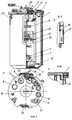
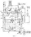
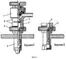
На фиг. 1 изображен общий вид МФУ, на фиг.2 - бокс установки, на фиг.3 а, б, в - общий вид ферментера и разрезы, на фиг.4 - схема соединений ферментера, на фиг. 5 - общий вид разъема, стерилизующегося электронагревом (РСЭН). In FIG. 1 shows a general view of the MFP, FIG. 2 shows a box of an installation, FIGS. 3 a, b, c shows a general view of the fermenter and sections; 5 is a general view of a connector sterilized by electric heating (RSEN).
Предлагаемая МФУ, фиг. 1, состоит из двух основных агрегатов - съемного, стерилизуемого в автоклаве ферментера 1 (рабочая вместимость 12 дм3, полная - 20 дм3) и стенда 2 (высота 1,9 м, ширина 0,7 м, длина 0,6 м). Стенд 2 включает стол-основание 3, изолирующий бокс 4 (объем 0,1 м3) и пульт управления 5. В последнем находятся быстросъемные блоки-модули 6-14 (подключающиеся к схеме, вставляющиеся спереди стенда и закрепляющиеся по месту посредством многоконтактных разъемов), обеспечивающие соответственно контроль и регулирование таких параметров как: температура (t) и интенсивность тепловыделения (qТ); частота вращения мешалки (nм); расход воздуха при аэрации (Qв); окислительно-восстановительный потенциал (eH); водородный показатель (pH); оптическая концентрация частиц (ОК); рабочий и аварийный уровни пены (Нп1 и Нп2 ); давление в ферментере (Pф) и боксе (Pб); продолжительность нагрева (τн) и сила тока (Iтр1) в первичной обмотке трансформатора - источника питания разъема стерилизующихся электронагревом разъемов (РСЭН), а также объемный расход инактивирующего раствора (Qр), подаваемого в форсунку бокса. Блок 15 обеспечивает программирование и включение проточных режимов культивирования, таких как: "qТ-СТАТ"; "eH-СТАТ", "pH-СТАТ", "ОК-СТАТ". Блок 16 - это общий блок питания. В столе-подставке 3 аналогичным образом размещены вторичные модули блоков 6-11, что обеспечивает компактность стенда 2. Исполнительные механизмы и системы обеспечения крепятся снизу, на задней стенке и сверху люка бокса 4. К ним относятся: электроприводы мешалки 17 и механического пеногасителя 18; регулирующий вентиль с электроприводом 19 и ротаметр 20, оборудованный фотоэлектрическим устройством контроля уровня поплавка и механизмом передвижения задатчика расхода QВ; соленоидные клапаны 21-25, приваренные на трубопроводах, предназначенных для подачи инактивирующего раствора и сжатого воздуха в форсунку, для подачи холодной и горячей воды в теплообменник ферментера из централизованной системы; соленоидные клапаны 26-29 - исполнительные механизмы систем дозирования растворов кислоты и щелочи, химического пеногасителя.The proposed MFP, FIG. 1, consists of two main units - removable, autoclavable fermenter 1 (working
В полость бокса герметично введены термометр сопротивления для ферментера и две электромагнитные катушки 30 от соленоидных клапанов, входящих в состав съемных дозаторов-трубопроводов, предназначенных для соединений ферментера с другими сосудами. На задней стенке бокса над уровнем стола и крышки ферментера герметично закреплены штеккеры разъемов для подключения датчиков pH и eH, вилки герметичных электроконтактных разъемов для подключения нефелометра, датчика уровней. Причем все разъемы и соединители, использованные в боксе, устойчивы и предназначены для работы в агрессивных условиях. A resistance thermometer for the fermenter and two electromagnetic coils 30 from the solenoid valves that are part of the removable pipettor designed for connecting the fermenter to other vessels are hermetically introduced into the cavity of the box. On the back wall of the box above the level of the table and the lid of the fermenter, the connectors plugs for connecting pH and eH sensors, plugs of sealed electrical connectors for connecting a nephelometer, level sensor are hermetically fixed. Moreover, all the connectors and connectors used in the box are stable and designed to work in aggressive conditions.
Бокс 4 (фиг. 1, 2) имеет: нижнюю камеру 31 с герметичной дверью для ферментера; два боковых и лобовое обзорное окна 32 и 33; две форкамеры 34 (проем высотой 180 мм, шириной 120 мм) с герметичными быстросъемными дверцами, подвешенными на петлях; один приточный фильтр 35 с пружинным клапаном для регулирования разрежения в боксе; два первичных фильтра 36 и два вторичных 37, герметично закрепляющихся соответственно изнутри и снаружи бокса. Причем каждый первичный фильтр 36 закрепляется в узкопрофильной камере, дном которой является крыша форкамеры. Форсунка для обработки инактивирующим раствором (аэрозолем) полости бокса и оборудования, находящегося в нем, подсоединена посредством вакуумных трубок к штуцерам входящих в бокс трубопроводов подачи раствора и сжатого воздуха. Box 4 (Fig. 1, 2) has: a lower chamber 31 with a sealed door for the fermenter; two side and frontal viewing windows 32 and 33; two 34 pre-chambers (aperture 180 mm high, 120 mm wide) with hermetic quick-release doors suspended on hinges; one
Герметичность силовой передачи и изоляции привода 17 от полости бокса обеспечивается магнитной муфтой (передача вращения через дно бокса и дно ферментера), а изоляция соединения привода МПГ: электродвигатель - промежуточный телескопический вал-магнитная муфта, обеспечивается телескопическим трубным кожухом 38 (см. фиг.1), в котором крепятся промежуточный вал с ведущей магнитной полумуфтой, при этом вращение магнитной муфтой передается через дно кожуха и крышку ферментера. The tightness of the power transmission and isolation of the
Ферментер (фиг.3, 4) представляет собой герметичный цилиндрический сосуд 1 с крышкой 2 и содержит перемешивающее устройство с двумя турбинными 6-лопастными мешалками 3, механический пеногаситель с рабочим органом в виде турбинной, закрытой двумя дисками, 4-лопастной мешалки 4, имеющими в качестве устройств для силовых передач магнитные муфты 5 и 6. Кроме того, ферментер содержит: трубчатый кольцевой барботер 7 с вентилем 8 и фильтром 9; сифон 10 (труба для заполнения-опорожнения с вентилем 11; трубчатый теплообменник 12 со штуцерами 13; два клапана 14 - для подсоединения внешнего (съемного) проточного контура; рубашку-конденсатосборник 15 и фильтр 16, обеспечивающие подсушку и стерилизацию выходящих газов; боковую камеру 17 для крепления электродов 18 (pH и eH); комбинированный датчик 19 рабочих уровней жидкости, пены и аварийного уровня пены; центробежный насос 20, предназначенный для деаэрации и прокачки КЖ через проточный контур и закрепленный на верхней опорной крестовине 21; окна 22 и 23 - для подсветки и обзора полости ферментера; четыре отражательные перегородки 24 (пластины, приваренные к трубам теплообменника, сифона и барботера); гильзу 25 - для датчика температуры. В качестве опорных подшипников использованы: для вала МПГ - подшипники качения 26; для вала мешалки - подшипники скольжения 27, 28. Оборудование 3-14, 16, 19-21, 24-28 входит в сборку крышки 2, остальное - в сборку сосуда 1. The fermenter (figure 3, 4) is a sealed
Корпусы фильтров 9, 16 закрываются герметичными крышками, снизу которых крепятся фильтр-патроны, а сверху имеются штуцеры 13 (как и на теплообменнике). The
Фильтр 9 соединен с барботером 7 через сквозное отверстие под седлом в корпусе сильфонного вентиля 8, так что при открытом вентиле воздух, подаваемый на аэрацию, поступает в ферментер (заполненный жидкостью) не из барботера, а из вентиля. Вместо вентиля в его корпусе может крепиться соленоидный клапан, при необходимости открываемый вручную с помощью постоянного магнита. Из ферментера аэрирующий воздух поступает вначале в рубашку 15 через отверстие в обечайке под крышкой 1 (где происходит конденсация влаги под действием отрицательного градиента температур наружной стенки рубашки и выходящего воздуха), затем выходит из рубашки через уплотнительную бобышку, расположенную с противоположной стороны (см. фиг.3, разрез А-А), проходит через радиальное отверстие в крышке и по соединительной трубе поступает в фильтр 16 и выходит в линию вакуума (см. фиг.4). При этом, поскольку температура крышки, соединительной трубы с фильтром выше температуры в рубашке, постольку исключается конденсация остаточной влаги в фильтре 16. Так как оптимальная температура большинства процессов более 28oC, нормальная температура в рабочем помещении 18-22oC, а температура крышки и фильтра 16 выше температуры полости при постоянно работающем МПГ (нагрев от трения в подшипниках 26).The
Штуцер 13 - это ответная часть самозапирающегося подпружиненным клапаном разъема. Вентиль 11 и клапан 14 - ответные части разъема, стерилизующегося электронагревом (РСЭН), посредством которого с ферментером соединяются дозаторы-трубопроводы и проточный контур. The fitting 13 is the counterpart of the self-locking spring-loaded valve connector.
Разъем РСЭН (фиг.5) состоит из двух основных частей - сильфонного вентиля 1 и пружинного клапана 2, герметично соединяющихся между собой через теплостойкую прокладку 3 накидной гайкой 4 или фланцами (возможный вариант). Вентиль и клапан могут соединяться с оборудованием посредством сварки. Клапан может крепиться на оборудовании по вариантам I или II. Вентиль 1 имеет запираемое снаружи седло, шток с прокладочным венцом 5 и с трехгранным толкателем 6, для последовательного открывания седла и подсоединенного к вентилю пружинного клапана, отрегулированного на заданное давление. Под седлом вентиля имеется цилиндрическая обечайка 7, образующая соединительную "глухую" камеру. Обечайка 7, выполняющая в разъеме, функцию электронагревательного элемента, изготовлена как одно целое с корпусом вентиля и имеет замыкающиеся через нее токосъемные контактные кольца 8, к которым посредством гибких изолированных кабелей с подпружиненными контактными клещами или посредством шин с хомутами подключается вторичная обмотка трансформатора сварочного типа - источника питания, закрепленного на задней стенке бокса МФУ. При включении с пульта управления установки трансформатора на заданное с помощью реле время (30 с) в короткозамкнутой через обечайку - нагревательный элемент цепи возникает электрический ток силой порядка 700 А, при напряжении 0,45 В и мощности трансформатора 0,63 кВт. При этом за 30 с обечайка 7 нагревается до температуры 500-550oC, обеспечивая прогрев воздуха в закрытой с двух сторон ("глухой") камере до 300-325oC, что вызывает стерилизацию камеры. Когда в полости камеры находится жидкость (например, при отсоединении дозатора-трубопровода или проточного контура при работающем насосе), проводится два последовательных 30-секундных нагрева, первый - для выброса и испарения жидкости (1,5 см3) из камеры через клапан, второй - для окончательной стерилизации полости камеры. При данных кратковременных нагревах разъема корпус вентиля нагревается за счет теплопередачи от обечайки до температуры не более 90oC при условии, что исходная температура корпуса не превышает 50oC. Быстрое охлаждение разъемов, после нагрева, осуществляется в боксе МФУ путем обливания их раствором и последующим обдувом воздуха из форсунки.The RSEN connector (Fig. 5) consists of two main parts - a
Обеспечение достаточных асептических условий при работе установки достигается следующим образом. Ensuring sufficient aseptic conditions during operation of the installation is achieved as follows.
Для мойки, проверки герметичности ферментера и его проточного контура, пробоотборников (основного и резервного комплектов) в рабочем помещении оборудуются специальные рабочие места (возможно создание автоматизированных мест). For washing, checking the tightness of the fermenter and its flow path, samplers (main and backup sets), special workplaces are equipped in the working room (the creation of automated places is possible).
Фильтр-патроны ферментера и фильтры бокса проверяют на проницаемость на специальных стендах. Fermenter filter cartridges and box filters are checked for permeability at special stands.
Изолирующую эффективность бокса проверяют при вводе в эксплуатацию установки и при ее периодическом техническом обслуживании по существующим отработанным методикам. Стерилизацию ферментера, проточного контура и пробоотборников в автоклаве и химическую стерилизацию бокса проводят по режимам, отработанным в процессе испытаний этого оборудования и указанным в паспорте установки. The insulating efficiency of the box is checked during the commissioning of the installation and during its periodic maintenance according to existing proven methods. Sterilization of the fermenter, flow path and samplers in the autoclave and chemical sterilization of the box is carried out according to the modes worked out during the testing of this equipment and indicated in the installation passport.
Аэрозольные обработки бокса инактивирующим раствором из форсунки проводятся перед выполнением стерильных соединений и после, а также после внесения в бокс из рабочего помещения заменяемых съемных пробоотборников, проточного контура и любых других элементов. Перед извлечением перечисленного оборудования из бокса проводится его обработка в форкамерах. По окончании работы проводится полная обработка бокса, включающая, при необходимости, обработку и асептическую замену первичных вытяжных фильтров. Для чего вентиль на линии барботера открывают (соединяя приточный фильтр непосредственно с воздушной полостью ферментера), к штуцеру этого фильтра подсоединяют резиновую грушу, сжимающуюся под разрежением - 0,2 кгс•см2, к штуцеру вытяжного фильтра подсоединяют резиновую трубку с зажимом и ответным штуцером от клапанного самозапирающегося разъема, через который ферментер вакуумируют до заданного значения включением побудителя аэрации.Aerosol treatments of the box with an inactivating solution from the nozzle are carried out before sterile connections are made and after, as well as after the introduction of replaceable removable samplers, flow path and any other elements into the box from the working room. Before removing the listed equipment from the box, it is processed in prechambers. At the end of the work, the box is completely processed, including, if necessary, processing and aseptic replacement of primary exhaust filters. For this, the valve on the bubbler line is opened (by connecting the supply filter directly to the air cavity of the fermenter), a rubber bulb is pressed to the nozzle of this filter, which is compressed under vacuum - 0.2 kgf • cm 2 , and a rubber tube with a clamp and a return fitting is connected to the exhaust filter nozzle from a valve self-locking connector through which the fermenter is evacuated to a predetermined value by turning on the aeration inducer.
Аналогичным образом в стерильном (подготовленном к работе) сменном ферментере создается небольшое избыточное давление с подсоединением вместо груши специального раздувающегося до заданного объема эластичного резинового баллончика. Similarly, in a sterile (ready-to-use) interchangeable fermenter, a slight excess pressure is created with the use of a special elastic rubber can swell to a predetermined volume instead of a pear.
Таким образом, транспортирование ферментера перед работой и после может осуществляться с обеспечением индикации его герметичности, а для транспортирования проточного контура, сосудов-дозаторов и пробоотборника могут использоваться герметичные пеналы. Thus, transportation of the fermenter before and after can be carried out with an indication of its tightness, and sealed canisters can be used to transport the flow path, metering vessels and sampler.
Список литературы
1. Кантере В.М., Крамм Э.А. Анализ лабораторных установок для культивирования микроорганизмов: Обзор,- М., 1973, сер. VI.List of references
1. Kantere V.M., Kramm E.A. Analysis of laboratory plants for the cultivation of microorganisms: Review, - M., 1973, ser. VI.
2. Брусиловский Л.П., Банникова Л.А, Вайнберг И.А. Управление процессами культивирования микроорганизмов заквасок и кисломолочных продуктов. - М.: Легкая и пищевая промышленность, 1982. 2. Brusilovsky L.P., Bannikova L.A., Weinberg I.A. Management of the cultivation of microorganisms of starter cultures and fermented milk products. - M .: Light and food industry, 1982.
3. Арзамасцев А.А. Современное оборудование для ферментационных исследований на выставке "Биохимия-84"// Ферментная и спиртовая промышленность, -1985, N5, с. 42-44. 3. Arzamastsev A.A. Modern equipment for fermentation research at the exhibition "Biochemistry-84" // Enzyme and alcohol industry, -1985, N5, p. 42-44.
4. Fermenters Etectrolux. //Proc.Biochem, -1977, vol. 12, N 3, p.9. 4. Fermenters Etectrolux. //Proc.Biochem, -1977, vol. 12,
5. Виестур У.Э и др. Культивирование микроорганизмов: Биоинженерные основы / Виестур У.Э., Кристапсонс М.Ж., Былинкина Е.С. - М.: Пищевая промышленность, 1980. 5. Viestur U.E. et al. Cultivation of microorganisms: Bioengineering fundamentals / Viestur U.E., Kristapsons M.Zh., Bylinkina ES - M.: Food Industry, 1980.
6. Чагин Б.А., Лосев В.А. Полупромышленная установка с аппаратурой АНКУМ-2М.: Тезисы докл. Всесоюзной конференции, посвященные контролю и управлению биохимическими процессами/ Всесоюзное микробиологическое общество. - Горький, 1985. 6. Chagin B.A., Losev V.A. Semi-industrial installation with ANKUM-2M equipment: Abstracts dokl. All-Union Conference on the Control and Management of Biochemical Processes / All-Union Microbiological Society. - Gorky, 1985.
7. Технические системы культивирования микроорганизмов. / [У.Э. Виестур, В.Д. Прокопенко, М.Ж. Кристапсон и др.; Под ред. У.Э. Виестура]. - Рига: Зинатне, 1978. 7. Technical systems for the cultivation of microorganisms. / [W.E. Viestur, V.D. Prokopenko, M.Zh. Kristapson et al .; Ed. W.E. Viestura]. - Riga: Zinatne, 1978.
8. Кристапсонс М.Ж., Виестур У.Э. Стенд ФС-5А для культивирования аэробных микроорганизмов. В кн.: Управляемый микробный синтез. - Рига: Зинатне, 1973, с.71-76. 8. Kristapsons M.Zh., Viestur U.E. Stand FS-5A for the cultivation of aerobic microorganisms. In: Guided Microbial Synthesis. - Riga: Zinatne, 1973, pp. 71-76.
9. Эксплуатация и усовершенствование ферментационных установок: [Сб.ст. / АН ЛатвССР, Ин-т микробиологии им. Августа Кирхенштейна; Редкол.: М.Ж. Кристапсонс (отв.ред.) и др.]. - Рига: Зинатне, 1986. 9. Operation and improvement of fermentation plants: [Sat. / Academy of Sciences of Latvia, Institute of Microbiology named after Augustus Kirchenstein; Editorial: M.Zh. Kristapsons (ed.), Etc.]. - Riga: Zinatne, 1986.
10. Блохина И. Н. и др. Управление процессами культивирования микроорганизмов: (Систем. подход) / И.Н.Блохина, В.И. Огарков, Г.А. Угодчиков. - Горький: Волго-Вятское книжное изд-во, 1983. 10. Blokhina I. N. and others. Management of the processes of cultivation of microorganisms: (System. Approach) / I. N. Blokhina, V. I. Ogarkov, G.A. Ugodchikov. - Gorky: Volga-Vyatka Book Publishing House, 1983.
11. Серия ферментеров "Биостат": Проспект / Фирма "B.BRAUN", - ФРГ. 11. A series of fermenters "Biostat": Prospect / Firm "B.BRAUN", - Germany.
12. Ферментеры: Проспект /Фирма "Biotek", Швеция. 12. Fermenters: Prospect / Firm "Biotek", Sweden.
13. Гительзон И.И., Терсков И.А., Ковров Б.К. и др. Экспериментальная, биологическая установка "Биостенд - I" - В кн.: Инженерные проблемы микробиологического синтеза / Под ред. Е.С. Былинкиной, В.В. Бирюкова. - М., 1969, с. 101-104. 13. Gitelzon I.I., Terskov I.A., Kovrov B.K. et al. Experimental, biological installation "Biostend - I" - In the book: Engineering Problems of Microbiological Synthesis / Ed. E.S. Bylinkina, V.V. Biryukova. - M., 1969, p. 101-104.
14. Ферментеры: Проспект / Фирма "Marubishi Trading Со ltd ", Япония. 14. Fermenters: Prospect / Firm "Marubishi Trading Co. ltd", Japan.
15. Установка для культивирования микроорганизмов "Дон-3": Проспект / МНТЦ "Биореактор". - М., 1991. 15. Installation for the cultivation of microorganisms "Don-3": Prospect / ISTC "Bioreactor". - M., 1991.
16. Special feature fermentation// Proc. Biochem, 1981, vol. 35, N 3, p. 36-41. 16. Special feature fermentation // Proc. Biochem, 1981, vol. 35,
17. Fermentation survey// Proc.Biochem, 1978, vol. 13, N 5, p. 38-43. 17. Fermentation survey // Proc. Biochem, 1978, vol. 13,
18. Solomons G. Survey of laboratory fermenters// Proc. Bochem, - 1970, vol. 6, N 8, р. 36-38. 18. Solomons G. Survey of laboratory fermenters // Proc. Bochem, - 1970, vol. 6,
19. Elsworth R. Safety in fermenters// Proc.Biochem, - 1970, vol. 5, N 6, р. 30-32. 19. Elsworth R. Safety in fermenters // Proc. Biochem, - 1970, vol. 5,
20. Комков А.С. и др. Проблемы современного лабораторного ферментера : Сборник / Прикладная биофизика микробов. - Горький, 1984, с. 113-114. 20. Komkov A.S. et al. Problems of a modern laboratory fermenter: Collection / Applied Biophysics of Microbes. - Gorky, 1984, p. 113-114.
21. Cameron G., Godfrey E.I. Magnetic drivers// Advances in microbiol. engineering, part 2, - 1974, p. 821-835. 21. Cameron G., Godfrey E.I. Magnetic drivers // Advances in microbiol. engineering,
22. Матвеев В.Е. Основы асептики в технологии чистых микробиологических препаратов. - М.: Легкая и пищевая промышленность, 1981. 22. Matveev V.E. The basics of asepsis in the technology of pure microbiological preparations. - M .: Light and food industry, 1981.
23. Lundell R., Laiho P. Engineering of fermentation plants. Design aspects// Proc. Biochem, - 1976, vol 11, p. 13-17. 23. Lundell R., Laiho P. Engineering of fermentation plants. Design aspects // Proc. Biochem, - 1976,
24. Sitting W. The present state of fermentation reactors// J.Chem.Technol. Biotechnol., - 1982, vol. 32, p. 47-58. 24. Sitting W. The present state of fermentation reactors // J. Chem. Technology. Biotechnol., 1982, vol. 32, p. 47-58.
25. Flickinger M.C., Sancone E.B. Pilot- and production - scale containment of cytotexic and oncogenic fermentation processes// Biotechnol. Bioeng. , - 1984, vol. 26, N 8, p. 860-870. 25. Flickinger M.C., Sancone E.B. Pilot- and production - scale containment of cytotexic and oncogenic fermentation processes // Biotechnol. Bioeng. , - 1984, vol. 26,
26. Harris-Smih P., Evans C.G. Bioengineering and protection during hazardous microbiological processes// Advances in microbiol. engineering, - 1974, part 2, p. 837-855. 26. Harris-Smih P., Evans C.G. Bioengineering and protection during hazardous microbiological processes // Advances in microbiol. engineering, - 1974,
27. Darlow H. M. , Elsworth R. Methods in Microbiology. - Academic Press-London and New York, - 1969, vol. 1, p. 123; 169. 27. Darlow H. M., Elsworth R. Methods in Microbiology. - Academic Press-London and New York, - 1969, vol. 1, p. 123; 169.
28. Heine W., Thunert A. Unterdruckisolatoren zur Arbeit mit Pathogenen Heimen// Ztschr. med. Mikrobiol. Immunol, - 1969. Bd, 155, H.1. s. 81-92. 28. Heine W., Thunert A. Unterdruckisolatoren zur Arbeit mit Pathogenen Heimen // Ztschr. med. Mikrobiol. Immunol, - 1969. Bd, 155, H.1. s. 81-92.
29. Осенькина В.А., Бойко В.И., Токарев И.А. Ферментационная аппаратура для стерильных микробиологических процессов. В кн.: Ферментационная аппаратура. - Рига: Зинатне, 1980, c. 11-20. 29. Ostankina V.A., Boyko V.I., Tokarev I.A. Fermentation apparatus for sterile microbiological processes. In: Fermentation apparatus. - Riga: Zinatne, 1980, p. 11-20.
30/ Kludas Н., Stache В., Stansch E. Die Verwendung des Ankum - 2 - Fermenters zur Locsung speriller Probleme der Bakterieneznachrung in der Impfstaffproduktion// Arch. Exp. veterinaermed, - 1983. Bd. 37, H. 4, s. 533-539. 30 / Kludas N., Stache B., Stansch E. Die Verwendung des Ankum - 2 - Fermenters zur Locsung speriller Probleme der Bakterieneznachrung in der Impfstaffproduktion // Arch. Exp. veterinaermed, - 1983. Bd. 37, H. 4, s. 533-539.
31. West D. L, Chatigny M.A. Design of microbiological and biochemical research facilities. - Laboratory Safety : Principles and Practices / Ed. B. M. Miller et al. - Washington, - 1986, p. 124-137. 31. West D. L, Chatigny M.A. Design of microbiological and biochemical research facilities. - Laboratory Safety: Principles and Practices / Ed. B. M. Miller et al. - Washington, - 1986, p. 124-137.
32. Fermenter// Nature, - 1982, vol. 298, N 5874, p. XV. 32. Fermenter // Nature, - 1982, vol. 298, N 5874, p. Xv.
33. Cnatigny M. Primarily Barriers. - Laboratory Safety: Priciples and Practices /Ed. B.M. Miller et al// Amer.Soc. of Microbiol., 1986, Ch.19, p. 144-163. 33. Cnatigny M. Primarily Barriers. - Laboratory Safety: Priciples and Practices / Ed. B.M. Miller et al // Amer.Soc. of Microbiol., 1986, Ch. 19, p. 144-163.
34. Бокс с форкамерой 4БП1-2М: Проспект / ВПО "Биопрепарат"; Изготовитель Опытно-конструк. бюро тонкого биол. машиностроения, - Кириши, 1975. 34. Boxing with 4BP1-2M prechamber: Prospect / VPO Biopreparat; Manufacturer Prototype. Bureau of Fine Biol. mechanical engineering, - Kirishi, 1975.
35. А. с. 1446519 [СССР]. Устройство для стерильного отбора микробиологических проб из аппаратов/ Грозненское НПО "Промавтоматика"; Авт. изобрет. Т. М. Керимов. - Заявл. 01.04.85, N 3877200/23-26; Опубл. в ОИ, 1988, N 47, МКИ A2 G 01 N 1/10. 35. A. p. 1446519 [USSR]. Device for sterile sampling of microbiological samples from devices / Grozny NPO Promavtomatika; Auth. invented T. M. Kerimov. - Declared. 04/01/85, N 3877200 / 23-26; Publ. in OI, 1988, N 47, MKI A2 G 01
36. Fichter A. Die kontinuierliche zuchtung von Mikroorganismes als apparatus Problem //Biotechn. Bioeng., - 1965, Bd. 7, H. 1, s. 101-128. 36. Fichter A. Die kontinuierliche zuchtung von Mikroorganismes als apparatus Problem // Biotechn. Bioeng., - 1965, Bd. 7, H. 1, s. 101-128.
37. А.с. 1536243 [СССР]. Устройство для стерильного отбора проб из ферментера/ Институт биохимии и физиологии микр.; Авт. В.А. Ежов, Д.Е.Лузин. - Заявл. 30.03.88, N 4395843/31-26; Опубл. в ОИ, 1990, N 2, МКИ G 01 N 1/10. 37. A.S. 1536243 [USSR]. A device for sterile sampling from a fermenter / Institute of Biochemistry and Physiology, mic .; Auth. V.A. Yezhov, D.E. Luzin. - Declared. 03/30/88, N 4395843 / 31-26; Publ. in OI, 1990,
38. А. с. 1495673 [СССР]. Сосуд для хранения и передачи стерильных жидкостей/ Всесоюз. научно-иссл. проект. ин-т приклад. биохимии; Авт. Л.И. Бережная, И.Д. Поляков. - Заявл. 22.07.87, N 4288970/28-13; Опубл. в ОИ, 1989, N 27, МКИ G 01 N 1/10. 38. A. p. 1495673 [USSR]. A vessel for the storage and transfer of sterile fluids / All-Union. scientific research project. institute butt. biochemistry; Auth. L.I. Berezhnaya, I.D. Poles. - Declared. 07.22.87, N 4288970 / 28-13; Publ. in OI, 1989,
39. А.с. 1465734 [СССР]. Устройство для отбора жидких проб из аппаратов культивирования/ Грозненское НПО "Промавтоматика"; Авт. В.Т. Пасиченко. - Заявл. 03.08.87, N 4293513/24-26; Опубл. в ОИ, 1989, N 10, МКИ G 01 N 1/10. 39. A.S. 1465734 [USSR]. Device for sampling liquid samples from cultivation apparatus / Grozny NPO Promavtomatika; Auth. V.T. Pasichenko. - Declared. 08/03/87, N 4293513 / 24-26; Publ. in OI, 1989,
40. А. с. 913121 [СССР]. Устройство для отбора проб культуры; Авт. Б.А. Клюшин, А. И. Воронин, С.Б. Сперанский. - Заявл. 14.07.80, N 2955328/23-26; Опубл. в ОИ, 1982, N 10, МКИ G 01 N 1/10. 40. A. p. 913121 [USSR]. Device for sampling culture; Auth. B.A. Klyushin, A.I. Voronin, S.B. Speransky. - Declared. 07/14/80, N 2955328 / 23-26; Publ. in OI, 1982,
41. А. с. 1543287 [СССР]. Устройство для герметичного отбора проб жидкости/ ВНИИ молекулярной биологии; Авт. В.М. Андрияхов. - Заявл. 21.12.87, N 4346409/23-26; Опубл. в ОИ, 1990, N 6, МКИ G 01 N 1/10. 41. A. p. 1543287 [USSR]. Device for tight sampling of liquid / All-Russian Research Institute of Molecular Biology; Auth. V.M. Andriyakhov. - Declared. 12.21.87, N 4346409 / 23-26; Publ. in OI, 1990,
42. Laboratory scale fermenter// Proc. Biochem., - 1975, vol. 10, N 4, p. 803-804. 42. Laboratory scale fermenter // Proc. Biochem., - 1975, vol. 10,
43. Raymahaasay S., Wase D.A. Sampling thick mycelial suspensions from an Air-lift fermenter// Biotechnol. and Bioeng., - 1984, vol. 26, N 7, p. 803-804. 43. Raymahaasay S., Wase D.A. Sampling thick mycelial suspensions from an Air-lift fermenter // Biotechnol. and Bioeng., - 1984, vol. 26,
44. Заявка 62-2796 [Япония]. Пробоотборник ферментационной среды/ Хитачи; Заяв. 06.11.81; Опубл. 21.01.87. 44. Application 62-2796 [Japan]. Fermentation Sampler / Hitachi;
45. Патент 222085 /ГДР/. Sterilisier-Bares Behalterventil/ D. Buchwald; Заявл. 23.03.84; Опубл. 08.05.85, A1 МКИ F 16 K 11/07. 45. Patent 222085 / GDR /. Sterilisier-Bares Behalterventil / D. Buchwald; Claim 03/23/84; Publ. 05/08/85, A1 MKI F 16
46. Патент DE 31074229 /ФРГ/. /Reiniglares Prolennventil; Заявл. 27.02.81; Опубл. 19.09.82, A1 МКИ F 16 K 51/00. 46. Patent DE 31074229 / Germany /. / Reiniglares Prolennventil; Claim 02/27/81; Publ. 09/19/82, A1 MKI F 16 K 51/00.
47. А. с. 952955 A [СССР] . Аппарат для выращивания микроорганизмов /Институт газа АН Украинской ССР; Авт. К.А. Лобуренко, С.И. Писарев, А.Е. Евсеев, П.В. Костогрыз. - Заявл. 22.02.80, N 2886807/28-13; МКИ G 01 N 1/10. 47. A. p. 952955 A [USSR]. Apparatus for growing microorganisms / Gas Institute of the Academy of Sciences of the Ukrainian SSR; Auth. K.A. Loburenko, S.I. Pisarev, A.E. Evseev, P.V. Bone-gnaw. - Declared. 02.22.80, N 2886807 / 28-13; MKI G 01
Claims (3)
Priority Applications (1)
| Application Number | Priority Date | Filing Date | Title |
|---|---|---|---|
| RU96123689A RU2142995C1 (en) | 1996-12-18 | 1996-12-18 | Smaller fermentation plant (versions) |
Applications Claiming Priority (1)
| Application Number | Priority Date | Filing Date | Title |
|---|---|---|---|
| RU96123689A RU2142995C1 (en) | 1996-12-18 | 1996-12-18 | Smaller fermentation plant (versions) |
Publications (2)
| Publication Number | Publication Date |
|---|---|
| RU96123689A RU96123689A (en) | 1999-02-27 |
| RU2142995C1 true RU2142995C1 (en) | 1999-12-20 |
Family
ID=20188198
Family Applications (1)
| Application Number | Title | Priority Date | Filing Date |
|---|---|---|---|
| RU96123689A RU2142995C1 (en) | 1996-12-18 | 1996-12-18 | Smaller fermentation plant (versions) |
Country Status (1)
| Country | Link |
|---|---|
| RU (1) | RU2142995C1 (en) |
Cited By (4)
| Publication number | Priority date | Publication date | Assignee | Title |
|---|---|---|---|---|
| RU2307166C2 (en) * | 2005-11-10 | 2007-09-27 | Всероссийский научно-исследовательский и технологический институт биологической промышленности | Method for proximate determination of non-sterility of broth for microorganism, animal cell and virus cultivation in bioreactors |
| EA010617B1 (en) * | 2007-02-12 | 2008-10-30 | Николай Федорович Парков | Protection module for process equipment |
| RU2415912C2 (en) * | 2005-05-30 | 2011-04-10 | Новартис Вэксинес Энд Дайэгностикс Гмбх Унд Ко. Кг | Fermenter system for bio-technical processes |
| RU2480520C1 (en) * | 2011-10-03 | 2013-04-27 | Федеральное государственное бюджетное образовательное учреждение высшего профессионального образования Воронежская государственная технологическая академия (ФГБОУ ВПО ВГТА) | Method of controlling processes of obtaining and drying enzyme preparations |
-
1996
- 1996-12-18 RU RU96123689A patent/RU2142995C1/en not_active IP Right Cessation
Non-Patent Citations (1)
| Title |
|---|
| Fermenter. "Nature", 1982, v.298, N 5974, P.XV. * |
Cited By (4)
| Publication number | Priority date | Publication date | Assignee | Title |
|---|---|---|---|---|
| RU2415912C2 (en) * | 2005-05-30 | 2011-04-10 | Новартис Вэксинес Энд Дайэгностикс Гмбх Унд Ко. Кг | Fermenter system for bio-technical processes |
| RU2307166C2 (en) * | 2005-11-10 | 2007-09-27 | Всероссийский научно-исследовательский и технологический институт биологической промышленности | Method for proximate determination of non-sterility of broth for microorganism, animal cell and virus cultivation in bioreactors |
| EA010617B1 (en) * | 2007-02-12 | 2008-10-30 | Николай Федорович Парков | Protection module for process equipment |
| RU2480520C1 (en) * | 2011-10-03 | 2013-04-27 | Федеральное государственное бюджетное образовательное учреждение высшего профессионального образования Воронежская государственная технологическая академия (ФГБОУ ВПО ВГТА) | Method of controlling processes of obtaining and drying enzyme preparations |
Similar Documents
| Publication | Publication Date | Title |
|---|---|---|
| CN105363051B (en) | Portable integrated Chlorine Dioxide Gas space disinfection device | |
| US20040168341A1 (en) | Methods for performing operations, a housing for such methods, and furnishings for such housing | |
| Elsworth et al. | A two litre scale continuous culture apparatus for micro‐organisms | |
| RU2142995C1 (en) | Smaller fermentation plant (versions) | |
| CN107586703A (en) | Microbial cultivation device | |
| CN109082377A (en) | A kind of medicine and pharmacology cell culture apparatus | |
| CN218951379U (en) | Indoor proliferation culture system of haematococcus pluvialis | |
| RU86184U1 (en) | FERMENTATION UNIT FOR CULTIVATION OF MICRO-ORGANISMS | |
| WO2016092073A1 (en) | Coupled systems of aeration, agitation and heat exchange for the culture of microorganisms in single use bioreactors | |
| CN212800015U (en) | Direct drinking water equipment integrating softening and sterilizing | |
| CN102973961B (en) | Ozone sterilization method for photobioreactor for culturing photosynthetic bacteria in large scale | |
| RU96123689A (en) | SMALL FERMENTATION UNIT | |
| CN210058100U (en) | Lactic acid bacteria preparation is with allotment jar | |
| Van Hemert | The “Bilthoven Unit” for submerged cultivation of microorganisms | |
| CN215517471U (en) | Carbon dioxide incubator | |
| US3445341A (en) | Fermentation apparatus with sterilization capabilities | |
| CN212610644U (en) | Laboratory small test device for microbial fermentation | |
| CN212713507U (en) | Filtering and sterilizing device for air inlet pipeline of fermentation tank | |
| CN211170693U (en) | Microorganism constant temperature culture integrated equipment | |
| CN222205222U (en) | Microorganism culture apparatus of circulation ventilation | |
| CN217516954U (en) | Automatic sealed shaking table case that disinfects | |
| Sharma et al. | Asepsis in bioreactors | |
| CN220597419U (en) | Culture device for anaerobic microorganisms | |
| CN217297876U (en) | Culture equipment for producing biological antibody | |
| CN115595241A (en) | Genetic engineering fermentation device and fermentation method |
Legal Events
| Date | Code | Title | Description |
|---|---|---|---|
| MM4A | The patent is invalid due to non-payment of fees |
Effective date: 20091219 |