RU2182995C2 - Apparatus for closing duct - Google Patents
Apparatus for closing duct Download PDFInfo
- Publication number
- RU2182995C2 RU2182995C2 RU2000116433A RU2000116433A RU2182995C2 RU 2182995 C2 RU2182995 C2 RU 2182995C2 RU 2000116433 A RU2000116433 A RU 2000116433A RU 2000116433 A RU2000116433 A RU 2000116433A RU 2182995 C2 RU2182995 C2 RU 2182995C2
- Authority
- RU
- Russia
- Prior art keywords
- axis
- cylindrical
- cavity
- diameter
- groove
- Prior art date
Links
- 238000004891 communication Methods 0.000 claims abstract description 4
- 230000000903 blocking effect Effects 0.000 claims description 8
- 241000282326 Felis catus Species 0.000 claims 1
- 238000007789 sealing Methods 0.000 abstract description 5
- 210000000056 organ Anatomy 0.000 abstract 4
- 238000000034 method Methods 0.000 abstract 1
- 239000000126 substance Substances 0.000 abstract 1
- 238000005516 engineering process Methods 0.000 description 3
- 230000007246 mechanism Effects 0.000 description 2
- 230000006835 compression Effects 0.000 description 1
- 238000007906 compression Methods 0.000 description 1
- 238000007667 floating Methods 0.000 description 1
- 238000011089 mechanical engineering Methods 0.000 description 1
- 230000000750 progressive effect Effects 0.000 description 1
Images
Landscapes
- Sealing Devices (AREA)
Abstract
Description
Изобретение относится к машиностроительной гидравлике и может быть использовано в гидравлических агрегатах и системах изделий авиационной и ракетной техники, а также в других областях техники. The invention relates to mechanical engineering hydraulics and can be used in hydraulic units and product systems of aviation and rocket technology, as well as in other fields of technology.
Известно устройство для перекрытия канала, содержащее корпус с полостью и пересекающим ее осесимметричным каналом, запорный орган, установленный в полости с возможностью возвратно-поступательного движения на величину Н в перпендикулярном оси канала направлении, перекрытия канала в одном из своих крайних положений и сообщения разделенных полостью частей канала в другом крайнем положении, и приводной шток, жестко связанный с запорным органом [1] . Недостатком этого устройства является большое гидравлическое сопротивление в открытом положении, вызванное внезапным расширением и последующим сужением канала в открытом положении. A device is known for blocking a channel, comprising a housing with a cavity and an axisymmetric channel crossing it, a locking member installed in the cavity with the possibility of reciprocating movement by a value of N in the direction perpendicular to the channel axis, blocking the channel in one of its extreme positions and communicating parts separated by the cavity channel in the other extreme position, and the drive rod, rigidly connected with the locking element [1]. The disadvantage of this device is the large hydraulic resistance in the open position caused by the sudden expansion and subsequent narrowing of the channel in the open position.
Указанного недостатка лишено устройство для перекрытия канала, содержащее корпус с цилиндрической полостью диаметром D1 и перпендикулярно пересекающим ее осесимметричным каналом, запорный орган в виде контактирующего с ней по своей наружной поверхности цилиндрического ползуна, установленный в полости с возможностью возвратно-поступательного движения на величину Н в перпендикулярном оси осесимметричного канала направлении, перекрытия осесимметричного канала в одном из своих крайних положений и сообщения разделенных полостью частей осесимметричного канала в другом крайнем положении посредством перепускного отверстия диаметра D в запорном органе, а также приводной шток, связанный с запорным органом, установленный с возможностью перемещения параллельно запорному органу на величину h, при этом ось цилиндрического ползуна пересечена с осью перепускного отверстия, которая, в свою очередь, параллельна оси осесимметричного канала, а также радиальное уплотнение, размещенное в канавке на цилиндрической поверхности одной из частей осесимметричного канала [2], выбранное в качестве прототипа.The indicated drawback is deprived of a device for blocking the channel, comprising a housing with a cylindrical cavity with a diameter of D 1 and an axisymmetric channel perpendicular to it, a locking member in the form of a cylindrical slide in contact with it on its outer surface, mounted in the cavity with the possibility of reciprocating movement by a value of N in perpendicular to the axisymmetric channel axis direction, overlapping the axisymmetric channel in one of its extreme positions and communication separated by a cavity part of the axisymmetric channel in the other extreme position by means of a bypass hole of diameter D in the locking body, and also a drive rod connected to the locking body, mounted to move parallel to the locking body by an amount h, while the axis of the cylindrical slider is crossed with the axis of the bypass hole, which, in turn, parallel to the axis of the axisymmetric channel, as well as a radial seal located in the groove on the cylindrical surface of one of the parts of the axisymmetric channel [2], selected in as a prototype.
Недостатками этого устройства являются сложность конструкции (из-за необходимости обработки пространственных уплотнительных поверхностей плавающих втулок), а также низкая надежность, вызванная неравномерным трением уплотнительных колец о запорный орган, имеющий остые кромки в местах выхода на его поверхность перепускного отверстия, что может привести к выходу колец из канавок, их скручиванию и заклиниванию в перепускном отверстии. The disadvantages of this device are the complexity of the design (due to the need for processing of the spatial sealing surfaces of the floating sleeves), as well as low reliability caused by uneven friction of the sealing rings on the locking member having remaining edges at the places where the bypass hole exits onto its surface, which can lead to exit rings from grooves, twisting and jamming in the bypass hole.
Техническим результатом, достигаемым с помощью заявленного изобретения, является упрощение конструкции и повышение надежности. The technical result achieved using the claimed invention is to simplify the design and increase reliability.
Этот результат достигается за счет того, что в известном устройстве для перекрытия канала, содержащем корпус с цилиндрической полостью диаметром D1 и перпендикулярно пересекающим ее осесимметричным каналом, запорный орган в виде контактирующего с ней по своей наружной поверхности цилиндрического ползуна, установленный в полости с возможностью возвратно-поступательного движения на величину Н в перпендикулярном оси осесимметричного канала направлении, перекрытия осесимметричного канала в одном из своих крайних положений и сообщения разделенных полостью частей осесимметричного канала в другом крайнем положении посредством перепускного отверстия диаметра D в запорном органе, а также приводной шток, связанный с запорным органом, установленный с возможностью перемещения параллельно запорному органу на величину h, при этом ось цилиндрического ползуна пересечена с осью перепускного отверстия, которая, в свою очередь, параллельна оси осесимметричного канала, а также радиальное уплотнение, размещенное в канавке на цилиндрической поверхности одной из частей осесимметричного канала, согласно изобретению в ползуне выполнено параллельное перепускному дополнительное отверстие диаметра D, ось которого размещена на расстоянии Н от оси перепускного отверстия и пересечена с осью ползуна, в дополнительном отверстии установлен контактирующий с ним по своей наружной поверхности цилиндрический плунжер с возможностью возвратно-поступательного движения относительно дополнительного отверстия, при этом в ползуне между дополнительным отверстием и ближайшем к нему торцем ползуна также выполнено соосное ему цилиндрическое отверстие, а в плунжере - сквозной паз, стенки которого параллельны оси ползуна, причем в цилиндрическом отверстии и пазе размещен приводной шток, в котором неподвижно установлен перпендикулярно осям плунжера и штока штифт диаметром d, а в боковых стенках паза выполнены перпендикулярные им наклонные под углом α по отношению к оси плунжера параллельные друг другу прорези шириной d со скругленными краями и размерами z и х в направлениях оси штока и оси плунжера соответственно, прорези выполнены с возможностью охвата выступающих из штока концов штифта, причем канавка с размещенным в ней радиальным уплотнением выполнена на цилиндрической поверхности диаметром D, ближайшей к наиболее удаленным от перепускного отверстия краям прорезей части осесимметричного канала, а дальний от оси полости торец канавки удален от нее на расстояние S, и конец плунжера, максимально удаленный от ближайших к перепускному отверстию краев прорезей на величину L, снабжен заходной фаской длиной f и минимальным диаметром D0, при этом ползун снабжен фиксатором углового положения по отношению к цилиндрической полости, и величины h и α определяются формулами
h=Н+z-d,
а величины длины плунжера R и L должны удовлетворять условиям
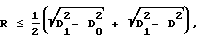
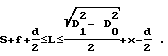
Так как заявленная совокупность существенных признаков устройства позволяет упростить конструкцию и повысить надежность, то заявленное устройство соответствует критерию "изобретательский уровень".This result is achieved due to the fact that in the known device for blocking the channel, comprising a body with a cylindrical cavity with a diameter D 1 and perpendicular to it intersecting the axisymmetric channel, a locking member in the form of a cylindrical slide in contact with it on its outer surface, mounted in the cavity with the possibility of return - progressive movement by the value of H in the direction perpendicular to the axis of the axisymmetric channel, overlapping the axisymmetric channel in one of its extreme positions and messages parts of the axisymmetric channel separated by a cavity in the other extreme position by means of a bypass hole of diameter D in the shut-off element, as well as a drive rod connected to the shut-off element, mounted to move parallel to the shut-off element by an amount h, while the axis of the cylindrical slider is crossed with the axis of the by-pass hole, which, in turn, is parallel to the axis of the axisymmetric channel, as well as a radial seal located in the groove on the cylindrical surface of one of the parts of the axisymmetric According to the invention, in the slider, an additional hole of diameter D parallel to the bypass is made, the axis of which is located at a distance H from the axis of the bypass hole and is crossed with the axis of the slider, a cylindrical plunger in contact with it on its outer surface is mounted with the possibility of reciprocating motion relative to the additional hole, while in the slider between the additional hole and the end face of the slider closest to it, also made coaxial to it a bore hole, and in the plunger there is a through groove, the walls of which are parallel to the axis of the slide, and in the cylindrical hole and groove there is a drive rod in which a pin with a diameter d is fixed perpendicular to the axes of the plunger and rod, and inclined at an angle perpendicular to them in the side walls of the groove α with respect to the axis of the plunger, slots parallel to each other with a width of d with rounded edges and dimensions z and x in the directions of the axis of the rod and the axis of the plunger, respectively, the slots are configured to cover protruding from the current of the ends of the pin, and the groove with the radial seal located in it is made on a cylindrical surface of diameter D closest to the edges of the slots of the axisymmetric channel that are farthest from the bypass hole, and the groove end farthest from the cavity axis is spaced from it by the distance S, and the end of the plunger, maximally distant from the edges of the slots closest to the bypass hole by an amount L, is equipped with a lead-in chamfer of length f and a minimum diameter D 0 , while the slider is equipped with a latch for the angular position with respect to of the cylindrical cavity, and the quantities h and α are determined by the formulas
h = H + zd,
and the plunger length values R and L must satisfy the conditions
Since the claimed combination of essential features of the device allows to simplify the design and increase reliability, the claimed device meets the criterion of "inventive step".
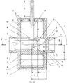
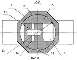
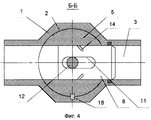
На фиг. 1 приведен пример конкретного выполнения устройства для перекрытия канала, продольный разрез, в открытом положении, на фиг.2 - то же, в перекрытом положении (штриховыми линиями изображен шток в положении, соответствующем фиг. 1), на фиг. 3 и 4 - поперечные сечения по А-А и Б-Б соответственно. In FIG. 1 shows an example of a specific embodiment of a device for blocking a channel, a longitudinal section, in the open position, FIG. 2 is the same in the blocked position (dashed lines show the rod in the position corresponding to FIG. 1), in FIG. 3 and 4 are cross-sections along A-A and B-B, respectively.
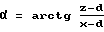
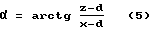
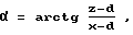
Устройство для перекрытия канала содержит сборный корпус 1 с цилиндрической полостью 2 диаметром D1 и пересекающим ее осесимметричным каналом 3. Ось полости 2 выполнена перпендикулярной оси канала 3. В полости 2 установлен запорный орган 4, выполненный в виде контактирующего с ней по своей наружной поверхности цилиндрического ползуна 5, в котором выполнены перепускное отверстие 6 диаметра D и параллельное перепускному дополнительное отверстие 7 диаметра D. Запорный орган 4 установлен с возможностью возвратно-поступательного движения на величину Н в перпендикулярном оси канала 3 направлении, что обеспечивается выполнением осевого размера полости 2, превышающим высоту ползуна 5 на величину Н. Запорный орган 4 установлен с возможностью сообщения разделенных полостью 2 частей канала 3 посредством перепускного отверстия 6 в одном своем крайнем положении (см. фиг.1). Оси отверстий 6 и 7 выполнены пересекающими ось ползуна 5 и параллельными оси канала 3. Ось дополнительного отверстия 7 размещена на расстоянии Н от оси перепускного отверстия 6. В отверстии 7 установлен контактирующий с ним по своей наружной поверхности цилиндрический плунжер 8 длиной R с возможностью возвратно-поступательного движения по отношению к дополнительному отверстию 7. В ползуне 5 между дополнительным отверстием 7 и ближайшем к нему торцем 9 ползуна 5 выполнено соосное ему цилиндрическое отверстие 10, а в плунжере 8 - сквозной паз 11 (на фиг. 1, 2 показан пунктиром), стенки которого параллельны оси ползуна 5. В цилиндрическом отверстии 10 и пазе 11 размещен приводной шток 12, связанный с запорным органом 4, установленный с возможностью перемещения параллельно запорному органу 4 на величину h. В штоке 12 неподвижно установлен перпендикулярно осям плунжера 8 и штока 12 штифт 13 диаметром d. В боковых стенках паза 11 выполнены перпендикулярные им наклонные под углом α по отношению к оси плунжера 8 параллельные друг другу прорези 14 шириной d со скругленными краями. Размеры прорезей 14 в направлениях оси штока 12 и оси плунжера 8 равны z и х соответственно. Прорези 14 охватывают выступающие из штока концы штифта 13. Поверхность ближайшей к наиболее удаленным от перепускного отверстия 6 краям прорезей части канала 3 (правой на фиг.1, 2, 3, 4) выполнена цилиндрической диаметром D и на ней выполнена канавка 15, в которой размещено радиальное уплотнение 16. Дальний от оси полости торец канавки 15 удален от этой оси на расстояние S, а конец плунжера, максимально удаленный от ближайших к перепускному отверстию 6 краев прорезей 14 (правый на фиг. 1, 2, 3, 4) на величину L, снабжен заходной фаской 17 длиной f и минимальным диаметром D0. Ползун 5 снабжен фиксатором 18 углового положения по отношению к цилиндрической полости 2, выполненном в виде штифта, входящего в паз ползуна 5. Из фиг.1 очевидно, что расстояния между центрами скругленных краев прорезей 14 равны (z-d) и (х-d) по направлению оси штока 12 и оси плунжера 8 соответственно. Так как ось прорезей наклонена под углом α по отношению к оси плунжера 8, то величина α определяется формулой:
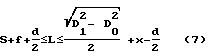
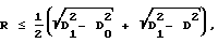
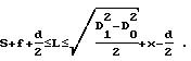
Величины R и L удовлетворяют условиям:

Устройство работает следующим образом. В исходном положении (см. фиг.1 и 3) части канала 3 сообщены перепускным отверстием 6, ползун 5 и шток 12 находятся в крайних верхних (по фиг.1) положениях. При этом плунжер 8 размещен внутри отверстия 7 и не выходит за пределы цилиндрической полости 2. Штифт 13 расположен в верхних, наиболее удаленных от перепускного отверстия 6 краях прорезей 14. При приведении штока 12 посредством одного из известных приводных механизмов, например механизма "винт-гайка" (на иллюстрациях не показан), в вертикальное движение сверху вниз (в общем случае по направлению от дополнительного отверстия к перепускному) штифт 13 нажимает на нижние края прорезей 14, создаваемое им усилие раскладывается на составляющие, параллельные оси ползуна и оси плунжера. Поскольку плунжер в исходном положении ограничен в своем движении цилиндрической стенкой полости 2, то он вместе с ползуном 5 опускается вниз до тех пор, пока его край с фаской минимальным диаметром D0 полностью не зайдет в отверстие правой части канала 3. Совмещение осей плунжера 8 и канала 3 в угловом направлении обеспечивается фиксатором 18. Совмещение осей плунжера 8 и канала 3 в вертикальном направлении обеспечивается благодаря тому, что межосевое расстояние между отверстиями 6 и 7 равно величине хода ползуна Н. Теперь плунжер 8 имеет возможность смещения вправо, что он и делает под воздействием составляющей, параллельной оси плунжера. При этом заходная фаска 17 обеспечивает равномерное сжатие радиального уплотнения 16 и вход в него наружной поверхности плунжера 8. Конечное положение устройства, при котором канал 3 перекрыт плунжером 8, показано на фиг.2 и 4. При необходимости открыть канал 3 шток 12 приводят в вертикальное движение снизу вверх (в общем случае по направлению от перепускного отверстия к дополнительному), штифт 13 нажимает на верхние края прорезей 14. Плунжер 8 передвигается влево, пока он не выйдет из правой части канала, и далее ползун 5 передвигается вверх, пока не упрется в верхнюю часть корпуса 1 и обе части канала 3 не сообщатся посредством перепускного отверстия 6. При этом ползун 5 и шток 12 находятся в крайних нижних положениях, а штифт 13 расположен в нижних, наиболее приближенных к перепускному отверстию 6 краях прорезей 14. Очевидно, что при перемещении штока вниз он сначала перемещается вместе с ползуном на величину Н, а затем дополнительно опускается на величину (z-d) при выдвижении плунжера вправо на величину (х-d), т.е. h= Н+z-d.The device for blocking the channel contains a
The values of R and L satisfy the conditions:
The device operates as follows. In the initial position (see FIGS. 1 and 3), the portions of the
Ограничения, накладываемые на величины S, R и L, обусловлены двумя условиями, необходимыми для функционирования устройства. The restrictions imposed on the values of S, R and L are due to two conditions necessary for the operation of the device.
Во-первых, в открытом состоянии плунжер 8 вписан в окружность сечения ползуна 5, т. е. в окружность диаметром D1, при этом штифт находится в верхнем правом крае прорезей. В предельном случае, когда плунжер краями заходной фаски касается стенок полости 2, правый край плунжера удален от оси ползуна на величину Q, определяемую по теореме Пифагора:
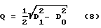
В то же время это расстояние (см. фиг.1) равно:
Q=L-x+0,5d (9)
Очевидно, что правый край плунжера всегда будет вписан в окружность диаметром D1 при условии:
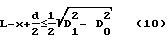
Аналогичным образом, в предельном случае, когда плунжер своим левым краем касается стенок полости 2, левый край плунжера удален от оси ползуна на величину W, определяемую по теореме Пифагора:
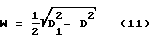
В то же время это расстояние (см. фиг.1) равно:
W=R-L+x-0,5d (12)
Очевидно, что левый край плунжера всегда будет вписан в окружность диаметром D1 при условии:
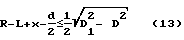
Сложив два вышеприведенных неравенства, получим приведенное в формуле изобретения ограничение для величины R.Firstly, in the open state, the
At the same time, this distance (see figure 1) is equal to:
Q = L-x + 0.5d (9)
Obviously, the right edge of the plunger will always be inscribed in a circle with a diameter of D 1 provided:
Similarly, in the extreme case, when the plunger touches the walls of the
At the same time, this distance (see figure 1) is equal to:
W = R-L + x-0.5d (12)
Obviously, the left edge of the plunger will always be inscribed in a circle with a diameter of D 1 provided:
Adding the above two inequalities, we obtain the restriction for R. given in the claims.
Во-вторых, в перекрытом состоянии плунжер 8 уплотнен по своей цилиндрической поверхности уплотнением 16, т.е. линия пересечения заходной фаски с наружным диаметром плунжера находится на расстоянии S или большем от оси ползуна, при этом штифт находится в нижнем левом крае прорезей. Это условие выполняется, если (см. фиг.2)
L-0,5d-f≥S, т.е. L≥S+0,5d+f
Объединив полученное неравенство с первым неравенством подпункта 1, получим приведенное в формуле изобретения ограничение для L.Secondly, in the closed state, the
L-0.5d-f≥S, i.e. L≥S + 0.5d + f
Combining the resulting inequality with the first inequality of
В результате использования заявленного изобретения существенно упрощается конструкция устройства - устраняются пространственные уплотнительные поверхности, они заменяются цилиндрическими, обработка которых существенно проще. Повышается надежность устройства, т.к. уплотнение при перекрытии канала испытывает полностью осесимметричную деформацию, что предотвращает возможность скручивания и заклинивания уплотнения в перепускном отверстии. Получение данного технического результата позволяет рекомендовать заявленное изобретение к внедрению в изделиях авиационной и космической техники, где повышение надежности агрегатов имеет приоритетное значение. As a result of using the claimed invention, the design of the device is greatly simplified - spatial sealing surfaces are eliminated, they are replaced by cylindrical ones, the processing of which is much simpler. The reliability of the device increases, because the seal when blocking the channel experiences a completely axisymmetric deformation, which prevents the possibility of twisting and jamming of the seal in the bypass hole. The receipt of this technical result allows us to recommend the claimed invention for implementation in aviation and space technology products, where improving the reliability of units is of priority.
Источники информации
1. Д. Ф.Гуревич, О.Н.Шпаков. Справочник конструктора трубопроводной арматуры. Л.: Машиностроение, 1987 г., стр. 111, рис.2.65,а.Sources of information
1. D.F. Gurevich, O.N. Shpakov. Handbook of pipeline fittings. L .: Engineering, 1987, p. 111, Fig. 2.65, a.
2. Заявка WO 85/01999 А1, 1985 г. (прототип). 2. Application WO 85/01999 A1, 1985 (prototype).
Claims (1)
h= Н+z-d,
а величины длины плунжера R и L должны удовлетворять условиям
h = H + zd,
and the plunger length values R and L must satisfy the conditions
Priority Applications (1)
| Application Number | Priority Date | Filing Date | Title |
|---|---|---|---|
| RU2000116433A RU2182995C2 (en) | 2000-06-27 | 2000-06-27 | Apparatus for closing duct |
Applications Claiming Priority (1)
| Application Number | Priority Date | Filing Date | Title |
|---|---|---|---|
| RU2000116433A RU2182995C2 (en) | 2000-06-27 | 2000-06-27 | Apparatus for closing duct |
Publications (2)
| Publication Number | Publication Date |
|---|---|
| RU2000116433A RU2000116433A (en) | 2002-04-27 |
| RU2182995C2 true RU2182995C2 (en) | 2002-05-27 |
Family
ID=20236699
Family Applications (1)
| Application Number | Title | Priority Date | Filing Date |
|---|---|---|---|
| RU2000116433A RU2182995C2 (en) | 2000-06-27 | 2000-06-27 | Apparatus for closing duct |
Country Status (1)
| Country | Link |
|---|---|
| RU (1) | RU2182995C2 (en) |
Cited By (2)
| Publication number | Priority date | Publication date | Assignee | Title |
|---|---|---|---|---|
| RU2597348C2 (en) * | 2014-09-10 | 2016-09-10 | Открытое акционерное общество "Ракетно-космическая корпорация "Энергия" имени С.П. Королева" | Channel shutoff device |
| RU2707789C1 (en) * | 2019-05-22 | 2019-11-29 | Публичное акционерное общество "Ракетно-космическая корпорация "Энергия" имени С.П. Королёва" | Channel shutoff device |
Citations (3)
| Publication number | Priority date | Publication date | Assignee | Title |
|---|---|---|---|---|
| US3605792A (en) * | 1969-10-31 | 1971-09-20 | Allied Ind Components | Valve with leak collector |
| GB1530579A (en) * | 1976-10-12 | 1978-11-01 | Valve Co Inc | Fluid control valve |
| WO1985001999A1 (en) * | 1983-11-04 | 1985-05-09 | Hydril Company | Cylindrical gate valve apparatus and method |
-
2000
- 2000-06-27 RU RU2000116433A patent/RU2182995C2/en active
Patent Citations (3)
| Publication number | Priority date | Publication date | Assignee | Title |
|---|---|---|---|---|
| US3605792A (en) * | 1969-10-31 | 1971-09-20 | Allied Ind Components | Valve with leak collector |
| GB1530579A (en) * | 1976-10-12 | 1978-11-01 | Valve Co Inc | Fluid control valve |
| WO1985001999A1 (en) * | 1983-11-04 | 1985-05-09 | Hydril Company | Cylindrical gate valve apparatus and method |
Non-Patent Citations (1)
| Title |
|---|
| ГУРЕВИЧ Д.Ф., ШПАКОВ О.Н. Справочник конструктора трубопроводной арматуры. - Л.: Машиностроение, 1987, с.108, рис.2.60. * |
Cited By (2)
| Publication number | Priority date | Publication date | Assignee | Title |
|---|---|---|---|---|
| RU2597348C2 (en) * | 2014-09-10 | 2016-09-10 | Открытое акционерное общество "Ракетно-космическая корпорация "Энергия" имени С.П. Королева" | Channel shutoff device |
| RU2707789C1 (en) * | 2019-05-22 | 2019-11-29 | Публичное акционерное общество "Ракетно-космическая корпорация "Энергия" имени С.П. Королёва" | Channel shutoff device |
Similar Documents
| Publication | Publication Date | Title |
|---|---|---|
| DE69804501T2 (en) | DISPLACEMENT PUMP | |
| DE102008027155B4 (en) | Solenoid valve | |
| DE102006000204A1 (en) | Linear electromagnet with stator core and piston | |
| DE4330616A1 (en) | Solenoid valve for vehicle ABS braking system - is sealed and retained in bore of aluminium@ housing by two caulked joints, one part-way down valve body and one at bore mouth | |
| EP3551512B1 (en) | Master cylinder arrangement with position sensor and sealing arrangement | |
| WO2011124198A1 (en) | Linear-travel measuring system | |
| EP4229245B1 (en) | Use of a hose for the fluidic connection of an outlet piece to a valve on a sanitary fitting, fluidic arrangement and corresponding sanitary fitting | |
| EP0633415B1 (en) | Electromagnetic switch valve | |
| DE112008001817B4 (en) | Linear actuator unit | |
| DE19635294A1 (en) | Solenoid-actuated 3/2 fluid power valve | |
| EP1774177B1 (en) | Piston pump with improved efficiency | |
| DE19915210A1 (en) | Fuel injection valve for internal combustion engine, with actuator acting via needle carrier on valve needle | |
| EP0666809B1 (en) | Hydraulic pressure relief valve | |
| EP1899634B1 (en) | Valve device | |
| DE19845346C2 (en) | Flow sensors, especially inductive flow sensors | |
| DE4405026A1 (en) | Micro fluid manipulator | |
| DE10065016A1 (en) | Electromagnet with magnetic armature | |
| EP3267080B1 (en) | Fluid valve with axial flow | |
| EP0786143B1 (en) | Quick break micro-switch with wedge profile on the contact lever swivellingly mounted in the switch | |
| DE102015118451B4 (en) | Solenoid valve | |
| EP0931964B1 (en) | Directional valve | |
| DE69408084T2 (en) | Electromagnetically actuated fuel metering and atomizing valve | |
| US5050781A (en) | Device for dosing a liquid contained in a first chamber and for transferring small doses thereof into a fluid flowing in a second chamber | |
| EP2164081A2 (en) | Switching magnet | |
| RU2597348C2 (en) | Channel shutoff device |