RU2192995C2 - Packing machine filling system and machine for filling container with main and additional products (versions) - Google Patents
Packing machine filling system and machine for filling container with main and additional products (versions) Download PDFInfo
- Publication number
- RU2192995C2 RU2192995C2 RU98123943/13A RU98123943A RU2192995C2 RU 2192995 C2 RU2192995 C2 RU 2192995C2 RU 98123943/13 A RU98123943/13 A RU 98123943/13A RU 98123943 A RU98123943 A RU 98123943A RU 2192995 C2 RU2192995 C2 RU 2192995C2
- Authority
- RU
- Russia
- Prior art keywords
- valve
- filling pipe
- filling
- main
- product
- Prior art date
Links
Images
Classifications
-
- B—PERFORMING OPERATIONS; TRANSPORTING
- B65—CONVEYING; PACKING; STORING; HANDLING THIN OR FILAMENTARY MATERIAL
- B65B—MACHINES, APPARATUS OR DEVICES FOR, OR METHODS OF, PACKAGING ARTICLES OR MATERIALS; UNPACKING
- B65B3/00—Packaging plastic material, semiliquids, liquids or mixed solids and liquids, in individual containers or receptacles, e.g. bags, sacks, boxes, cartons, cans, or jars
- B65B3/26—Methods or devices for controlling the quantity of the material fed or filled
- B65B3/30—Methods or devices for controlling the quantity of the material fed or filled by volumetric measurement
- B65B3/32—Methods or devices for controlling the quantity of the material fed or filled by volumetric measurement by pistons co-operating with measuring chambers
- B65B3/326—Methods or devices for controlling the quantity of the material fed or filled by volumetric measurement by pistons co-operating with measuring chambers for dosing several products to be mixed
-
- B—PERFORMING OPERATIONS; TRANSPORTING
- B65—CONVEYING; PACKING; STORING; HANDLING THIN OR FILAMENTARY MATERIAL
- B65B—MACHINES, APPARATUS OR DEVICES FOR, OR METHODS OF, PACKAGING ARTICLES OR MATERIALS; UNPACKING
- B65B39/00—Nozzles, funnels or guides for introducing articles or materials into containers or wrappers
- B65B39/001—Nozzles, funnels or guides for introducing articles or materials into containers or wrappers with flow cut-off means, e.g. valves
- B65B39/004—Nozzles, funnels or guides for introducing articles or materials into containers or wrappers with flow cut-off means, e.g. valves moving linearly
Landscapes
- Engineering & Computer Science (AREA)
- Mechanical Engineering (AREA)
- Supply Of Fluid Materials To The Packaging Location (AREA)
- Basic Packing Technique (AREA)
- Fluid-Pressure Circuits (AREA)
- Containers And Plastic Fillers For Packaging (AREA)
- Supplying Of Containers To The Packaging Station (AREA)
Abstract
Description
Настоящее изобретение относится к системе наполнения упаковочной машины для заполнения контейнера основным и дополнительным продуктом. The present invention relates to a filling system for a packaging machine for filling a container with a primary and secondary product.
Более точно изобретение относится к системе наполнения упаковочной машины, в которой используется многоступенчатый линейный исполнительный механизм клапана для обеспечения различных скоростей и объемов наполнения. More precisely, the invention relates to a filling system for a packaging machine that uses a multi-stage linear valve actuator to provide various filling speeds and volumes.
Ранее были предложены системы упаковочных машин, такие как раскрытая в международной публикации WO 96/09957, озаглавленной "Система упаковочной машины, предназначенная для заполнения контейнера основным и добавочным продуктами" и опубликованной 4 апреля 1996 года. Packaging machine systems have previously been proposed, such as disclosed in the international publication WO 96/09957, entitled “Packaging Machine System Designed to Fill a Container with Basic and Secondary Products” and published on April 4, 1996.
В данной отрасли сохраняется потребность в усовершенствованном устройстве для налива продукта, которое имеет повышенную точность наполнения и которое способно обеспечить наполнение контейнеров с различной величиной объема. In the industry, there remains a need for an improved product filling device that has improved filling accuracy and is capable of filling containers with different volume sizes.
Техническим результатом настоящего изобретения является создание системы наполнения упаковочной машины для заполнения контейнера основным и добавочным продуктом, имеющего многоступенчатый линейный исполнительный механизм клапана, обеспечивающий точность и равномерное наполнение контейнеров различных объемов и позволяющий получить повышенную точность при соединении двух продуктов, таких как сливки и сепарированное молоко, тем самым обеспечивая получение конечного продукта лучшего качества. The technical result of the present invention is the creation of a filling system for a packaging machine for filling a container with a main and additional product, having a multi-stage linear actuator valve, which ensures the accuracy and uniform filling of containers of various volumes and allows for increased accuracy when connecting two products, such as cream and separated milk, thereby providing the final product of the best quality.
Этот технический результат достигается тем, что в системе наполнения упаковочной машины для заполнения контейнера основным продуктом и добавочным продуктом, содержащей наполняющую трубу с клапаном на нижнем конце наполняющей трубы, находящимся в открытом состоянии в процессе наполнения, согласно изобретению имеется многоступенчатый линейный исполнительный механизм, присоединенный к клапану для приведения клапана в движение между закрытым положением и одним из первых выдвинутым открытым положением и вторым выдвинутым открытым положением для выборочного создания соответственно, по меньшей мере, первой и второй ширины отверстия клапана. This technical result is achieved in that in the filling system of a packaging machine for filling a container with a main product and an additional product containing a filling pipe with a valve at the lower end of the filling pipe in the open state during the filling process, according to the invention, there is a multi-stage linear actuator connected to a valve for driving the valve between the closed position and one of the first extended open position and the second extended open polo For selective creation, respectively, of at least the first and second widths of the valve openings.
Указанный технический результат достигается и тем, что в упаковочной машине для заполнения контейнера основным продуктом и добавочным продуктом, содержащей наполняющую трубу, имеющую внутреннюю полость, проходящую до выходного отверстия, клапанный узел, расположенный во внутренней полости наполняющей трубы и имеющий верхний конец и клапан, расположенный на нижнем конце, согласно изобретению имеется линейный исполнительный механизм клапана, присоединенный в рабочем положении к верхнему концу клапанного узла для установки клапана в множество дискретных положений относительно выходного отверстия наполняющей трубы для регулирования потока продукта через него. The specified technical result is achieved by the fact that in the packaging machine for filling the container with a main product and an additional product containing a filling pipe having an internal cavity extending to the outlet, a valve assembly located in the internal cavity of the filling pipe and having an upper end and a valve located at the lower end, according to the invention, there is a linear valve actuator connected in the working position to the upper end of the valve assembly for mounting the valve in m ozhestvo discrete positions with respect to the outlet opening of the fill pipe for controlling the flow of product therethrough.
Указанный технический результат достигается и тем, что в упаковочной машине для заполнения контейнера основным продуктом и добавочным продуктом, содержащей основную наполняющую трубу, имеющую внутреннюю полость, проходящую до выходного отверстия, вспомогательную наполняющую трубу, расположенную внутри внутренней полости основной наполняющей трубы и имеющую отверстие, расположенное вблизи выходного отверстия основной наполняющей трубы, многоступенчатый клапан, расположенный у отверстия вспомогательной наполняющей трубы, согласно изобретению имеется линейный исполнительный механизм клапана, присоединенный в рабочем положении к клапану для открытия клапана с обеспечением множества дискретных стадий открытия относительно отверстия вспомогательной наполняющей трубы, тем самым обеспечивая регулирование потока добавочного продукта через него. The specified technical result is achieved by the fact that in the packaging machine for filling the container with a main product and an additional product containing a main filling pipe having an internal cavity extending to the outlet, an auxiliary filling pipe located inside the internal cavity of the main filling pipe and having an opening located near the outlet of the main filling pipe, a multi-stage valve located at the opening of the auxiliary filling pipe, according to The invention has a linear valve actuator attached in the working position to the valve for opening the valve, providing a plurality of discrete opening steps relative to the opening of the auxiliary filling pipe, thereby controlling the flow of additional product through it.
Вспомогательная наполняющая труба может быть расположена концентрично внутри основной наполняющей трубы. The auxiliary filling pipe may be arranged concentrically inside the main filling pipe.
Линейный исполнительный механизм клапана может быть приспособлен для установки клапана в, по меньшей мере, два положения или в множество выбираемых положений. The linear valve actuator may be adapted to position the valve in at least two positions or in a plurality of selectable positions.
Основная наполняющая труба может быть подсоединена к источнику основного продукта. The main filling pipe may be connected to the source of the main product.
Вспомогательная наполняющая труба может быть подсоединена к источнику добавочного продукта. The auxiliary filling pipe may be connected to a source of additional product.
Отверстие вспомогательной наполняющей трубы может быть расположено вблизи выходного отверстия основной наполняющей трубы. The opening of the auxiliary filling pipe may be located near the outlet of the main filling pipe.
Линейный исполнительный механизм может быть приспособлен для пневматической установки клапана в, по меньшей мере, два выбираемых положения. The linear actuator may be adapted to pneumatically position the valve in at least two selectable positions.
Далее приводится более подробное описание изобретения со ссылками на чертежи, на которых изображено следующее:
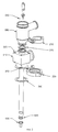
фиг. 1 изображает перспективный вид наполняющего устройства упаковочной машины в соответствии с настоящим изобретением;
фиг.2 - перспективный вид с пространственным разделением деталей наполняющего устройства в соответствии с настоящим изобретением;
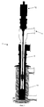
фиг.3 - боковое сечение наполняющего устройства в соответствии с настоящим изобретением, выполненное вдоль линии III-III на фиг.1;
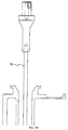
фиг. 4А - боковое сечение самой верхней части наполняющего устройства, показанного на фиг.3;
фиг. 4В - боковое сечение промежуточной секции наполняющего устройства, показанного на фиг.3;
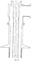
фиг. 4С - боковое сечение нижней концевой части наполняющего устройства, показанного на фиг.3, в закрытом положении;
фиг. 5 - боковое сечение нижней концевой части наполняющего устройства, показанного на фиг.3, при первой ступени или стадии его открытия;
фиг. 6 - боковое сечение нижней концевой части наполняющего устройства, показанного на фиг.3, при второй ступени или стадии его открытия.The following is a more detailed description of the invention with reference to the drawings, which depict the following:
FIG. 1 is a perspective view of a filling device of a packaging machine in accordance with the present invention;
figure 2 is a perspective view with a spatial separation of the parts of the filling device in accordance with the present invention;
figure 3 is a side section of the filling device in accordance with the present invention, made along the line III-III in figure 1;
FIG. 4A is a side section of the uppermost part of the filling device shown in FIG. 3;
FIG. 4B is a side section of an intermediate section of the filling device shown in FIG. 3;
FIG. 4C is a side section of the lower end portion of the filling device shown in FIG. 3 in the closed position;
FIG. 5 is a lateral section of the lower end portion of the filling device shown in FIG. 3 at the first stage or stage of its opening;
FIG. 6 is a lateral section of the lower end portion of the filling device shown in FIG. 3 during the second stage or stage of its opening.
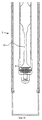
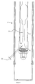
На фиг. 3 в целом показано наполняющее устройство 2 упаковочной машины в соответствии с предпочтительным вариантом осуществления настоящего изобретения. Общая конструкция наполняющего устройства 2 заявлена и описана в вышеупомянутой, одновременно находящейся на рассмотрении заявке на патент США 08/315246, поданной 29 сентября 1994 и в международной публикации WO 96/09957, опубликованной 4 апреля 1996. Поскольку заявка на патент США 08/315246 и международная публикация WO 96/09957 были включены в данную заявку в качестве ссылки, детали наполняющего устройства здесь далее не описаны. In FIG. 3 generally shows a
В целом наполняющее устройство 2 включает в себя впускное отверстие 4 для добавочного продукта, сообщенное с наполняющей трубой 6. Наполняющая труба 6 имеет открытый нижний конец 8 (фиг.4С). Вдоль внутренней полости наполняющей трубы 6 внутри нее проходит шток 10. Верхний конец штока 10 надежно сцеплен с линейным исполнительным механизмом 12 клапана (фиг.3). Исполнительный механизм 12 обеспечивает линейный привод штока 10 и его возвратно-поступательное перемещение вдоль его продольной оси. Линейный исполнительный механизм 12 может иметь одну из известных конструкций, таких как исполнительный механизм с механическим приводом, исполнительный механизм с пневмоприводом, исполнительный механизм с гидроприводом и т.п. В предпочтительном варианте осуществления исполнительный механизм выполнен с гидроприводом. Линейный исполнительный механизм 12 клапана может быть выдвинут для осуществления множества дискретных ступеней или стадий. Например, линейный исполнительный механизм 12 клапана может представлять собой двухступенчатый или двухстадийный исполнительный механизм, выполненный с возможностью приведения его в движение между отведенным положением, первым выдвинутым положением и вторым выдвинутым положением. In general, the
В качестве возможного варианта исполнительный механизм 12 может иметь более двух ступеней или стадий в зависимости от потребностей наполняющего устройства. Alternatively, the
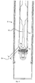
На фиг. 4С показана нижняя концевая часть наполняющего устройства 2, причем исполнительный механизм 12 показан в отведенном положении, следовательно, шток 10 герметично закрывает открытый конец 8 с помощью клапана 18. In FIG. 4C shows the lower end of the
На фиг. 5 показана нижняя концевая часть наполняющего устройства 2, причем линейный исполнительный механизм 12 выдвинут до первой ступени или стадии. При выдвижении его до первой ступени исполнительный механизм 12 приводит шток 10 в движение вниз, и шток 10 смещается на первое расстояние или ход клапана до первого положения. При первом выдвинутом положении создается отверстие 16 между клапаном 18 и нижним концом 8 наполняющей трубы 6. Ширина отверстия 16 обозначена D1.In FIG. 5 shows the lower end portion of the
На фиг. 6 показана нижняя часть наполняющего устройства 2, причем исполнительный механизм 12 выдвинут до второй ступени или стадии. При выдвижении его до второй ступени или стадии исполнительный механизм 12 приводит шток 10 в движение вниз, и шток 10 смещается до второго выдвинутого положения. При второй стадии отверстие 16 расширяется до ширины, обозначенной D2.In FIG. 6 shows the lower part of the
Как разъяснено выше, линейный исполнительный механизм 12 может иметь более двух ступеней выдвижения, и, таким образом, ширину отверстия 16 можно дискретно изменять на расстояния, отличные от D1 и D2. Значения D1 и D2 ширины зазора можно изменять в зависимости от конкретного случая применения. Ширина D1 может составлять 4 мм, в то время как ширина D2 может быть равна 10 мм, причем данные значения приведены исключительно в качестве примера.As explained above, the
За счет использования линейного исполнительного механизма 12, который выполнен с возможностью выдвижения на множество ступеней, устройство по предпочтительному варианту осуществления настоящего изобретения обеспечивает большую точность при заполнении контейнеров различных объемов, тем самым обеспечивается более равномерный профиль заполнения. Through the use of a
Несмотря на то что были показаны и описаны конкретные элементы, варианты осуществления и случаи применения настоящего изобретения, естественно, следует понимать, что изобретение не ограничено ими, поскольку специалисты в данной области могут выполнить модификации, особенно с учетом вышеизложенных идей. Следовательно, подразумевается, что приложенная формула изобретения охватывает такие модификации, которые обладают признаками, находящимися в рамках идеи и объема изобретения. Although specific elements, embodiments, and applications of the present invention have been shown and described, it should naturally be understood that the invention is not limited to them, as those skilled in the art can make modifications, especially in view of the above ideas. Therefore, it is understood that the appended claims cover such modifications that possess features that are within the spirit and scope of the invention.
Claims (10)
Applications Claiming Priority (2)
| Application Number | Priority Date | Filing Date | Title |
|---|---|---|---|
| US1866396P | 1996-05-30 | 1996-05-30 | |
| US60/018,663 | 1996-05-30 |
Publications (2)
| Publication Number | Publication Date |
|---|---|
| RU98123943A RU98123943A (en) | 2000-10-20 |
| RU2192995C2 true RU2192995C2 (en) | 2002-11-20 |
Family
ID=21789136
Family Applications (1)
| Application Number | Title | Priority Date | Filing Date |
|---|---|---|---|
| RU98123943/13A RU2192995C2 (en) | 1996-05-30 | 1997-05-30 | Packing machine filling system and machine for filling container with main and additional products (versions) |
Country Status (8)
| Country | Link |
|---|---|
| US (1) | US6158195A (en) |
| EP (1) | EP0929443A4 (en) |
| JP (1) | JP2000511498A (en) |
| AU (1) | AU725780B2 (en) |
| CA (1) | CA2253616C (en) |
| NO (1) | NO319100B1 (en) |
| RU (1) | RU2192995C2 (en) |
| WO (1) | WO1997045321A1 (en) |
Families Citing this family (9)
| Publication number | Priority date | Publication date | Assignee | Title |
|---|---|---|---|---|
| USD755928S1 (en) * | 2013-07-15 | 2016-05-10 | Bevcorp Llc | Filling valve |
| JP1628049S (en) * | 2017-05-19 | 2019-04-01 | ||
| US11104461B2 (en) | 2017-09-15 | 2021-08-31 | Campbell Soup Company | Two-phase filling apparatus and methods |
| USD905823S1 (en) * | 2017-11-06 | 2020-12-22 | Gema Switzerland Gmbh | Injector, in particular for spray coating devices |
| USD909531S1 (en) * | 2018-04-16 | 2021-02-02 | Amiad Water System Ltd. | Filtration system |
| USD907172S1 (en) * | 2018-04-16 | 2021-01-05 | Amiad Water System Ltd. | Filtration system |
| USD856480S1 (en) * | 2018-04-30 | 2019-08-13 | Eaton Intelligent Power Limited | Fluid conduit |
| USD856479S1 (en) * | 2018-04-30 | 2019-08-13 | Eaton Intelligent Power Limited | Fluid conduit |
| TWI847242B (en) * | 2022-08-31 | 2024-07-01 | 財團法人工業技術研究院 | Automatic liquid changing device and fluid delivery joint |
Citations (2)
| Publication number | Priority date | Publication date | Assignee | Title |
|---|---|---|---|---|
| US3559700A (en) * | 1969-01-21 | 1971-02-02 | Big Drum Inc | Method and apparatus for filling containers with multiple separate streams of viscous material |
| US5094276A (en) * | 1988-09-26 | 1992-03-10 | Fluid Packaging Co., Inc. | Mixing valve nozzle |
Family Cites Families (10)
| Publication number | Priority date | Publication date | Assignee | Title |
|---|---|---|---|---|
| US3952782A (en) * | 1973-11-28 | 1976-04-27 | Colgate-Palmolive Company | Apparatus for filling containers with composite fluent material |
| US4211263A (en) * | 1978-10-16 | 1980-07-08 | Velasco Scale Company | Dual fill rate liquid filler apparatus having a single control valve |
| US4337802A (en) * | 1980-09-30 | 1982-07-06 | Velasco Scale Company, Inc. | Method and apparatus for liquid filling of containers |
| EP0117329A3 (en) * | 1983-02-28 | 1984-12-27 | Liquipak International B.V. | Fluid dispensing nozzle and feeding apparatus, particularly for a packaging machine |
| SE437136B (en) * | 1984-03-08 | 1985-02-11 | Tetra Pak Int | SET AND DEVICE FOR MANUFACTURING AND FILLING OF PACKAGING CONTAINERS |
| US4630654A (en) * | 1984-08-10 | 1986-12-23 | Patrick Howard Gibson | Apparatus for liquid filling of containers |
| US5016687A (en) * | 1989-06-15 | 1991-05-21 | Shikoku Kakoki Co., Ltd. | Device for preventing liquid from dripping from filling nozzle of liquid filling machine |
| AU636198B2 (en) * | 1991-02-19 | 1993-04-22 | Shikoku Kakoki Co., Ltd. | Filling nozzle |
| US5687779A (en) * | 1992-09-17 | 1997-11-18 | Tetra Laval Holdings & Finance S.A. | Packaging machine system for filling primary and secondary products into a container |
| DE69532387T2 (en) * | 1994-09-29 | 2004-06-03 | Tetra Laval Holdings & Finance S.A. | Process for filling a container with cream and skimmed milk |
-
1997
- 1997-05-30 AU AU32984/97A patent/AU725780B2/en not_active Expired
- 1997-05-30 US US08/866,809 patent/US6158195A/en not_active Expired - Lifetime
- 1997-05-30 CA CA002253616A patent/CA2253616C/en not_active Expired - Lifetime
- 1997-05-30 WO PCT/US1997/009611 patent/WO1997045321A1/en not_active Ceased
- 1997-05-30 EP EP97928820A patent/EP0929443A4/en not_active Withdrawn
- 1997-05-30 RU RU98123943/13A patent/RU2192995C2/en active
- 1997-05-30 JP JP09543072A patent/JP2000511498A/en active Pending
-
1998
- 1998-11-16 NO NO19985333A patent/NO319100B1/en not_active IP Right Cessation
Patent Citations (2)
| Publication number | Priority date | Publication date | Assignee | Title |
|---|---|---|---|---|
| US3559700A (en) * | 1969-01-21 | 1971-02-02 | Big Drum Inc | Method and apparatus for filling containers with multiple separate streams of viscous material |
| US5094276A (en) * | 1988-09-26 | 1992-03-10 | Fluid Packaging Co., Inc. | Mixing valve nozzle |
Also Published As
| Publication number | Publication date |
|---|---|
| CA2253616A1 (en) | 1997-12-04 |
| JP2000511498A (en) | 2000-09-05 |
| EP0929443A4 (en) | 2006-09-20 |
| NO319100B1 (en) | 2005-06-20 |
| AU3298497A (en) | 1998-01-05 |
| US6158195A (en) | 2000-12-12 |
| NO985333L (en) | 1998-11-16 |
| AU725780B2 (en) | 2000-10-19 |
| WO1997045321A1 (en) | 1997-12-04 |
| EP0929443A1 (en) | 1999-07-21 |
| NO985333D0 (en) | 1998-11-16 |
| CA2253616C (en) | 2007-09-25 |
Similar Documents
| Publication | Publication Date | Title |
|---|---|---|
| RU2192995C2 (en) | Packing machine filling system and machine for filling container with main and additional products (versions) | |
| EP1310454B1 (en) | Valve unit for filling machines | |
| JP3809103B2 (en) | Booster pilot valve | |
| CA2410546C (en) | Actuator having dual piston surfaces | |
| US5758698A (en) | Fill system including a valve assembly and corresponding structure for reducing the mixing of product and air during container filling | |
| US5024584A (en) | Pump unit with adjustable piston stroke length | |
| EP0268458B1 (en) | Apparatus for driving piston by fluid pressure | |
| EP0299592A2 (en) | Driving device and method for double bellows dispensing unit | |
| EP1036598B1 (en) | High flow pneumatic adhesive applicator valve | |
| CN1175196C (en) | Valve with a valve body | |
| RU98123943A (en) | MULTI-STAGE EXECUTIVE VALVE MECHANISM FOR PACKING MACHINES | |
| EP3891402B1 (en) | Flow controller and driving apparatus including the same | |
| EP3698053A1 (en) | Oscillation cylinder arrangement | |
| CA2721905C (en) | Method and apparatus for dosing products | |
| EP0428406A1 (en) | Reciprocating actuator | |
| EP0488781B1 (en) | Pumping device and containers fitted therewith | |
| US6079596A (en) | Metering and dispensing assembly | |
| US5562018A (en) | Hydraulic valve | |
| KR0127421Y1 (en) | Gas spring with adjustable reaction force | |
| KR200392892Y1 (en) | Speed control apparatus of air cylinder | |
| JP2665071B2 (en) | Liquid control valve | |
| KR20050063237A (en) | Cylindrical cam type pneumator for ball valve | |
| JPH0783340A (en) | Exhaust valve | |
| WO2004057222A1 (en) | Valve actuation velocity control device | |
| GB2214241A (en) | Improvements in metering pumps |