RU2193473C1 - Adjustable chuck for holding broach - Google Patents
Adjustable chuck for holding broach Download PDFInfo
- Publication number
- RU2193473C1 RU2193473C1 RU2001119072A RU2001119072A RU2193473C1 RU 2193473 C1 RU2193473 C1 RU 2193473C1 RU 2001119072 A RU2001119072 A RU 2001119072A RU 2001119072 A RU2001119072 A RU 2001119072A RU 2193473 C1 RU2193473 C1 RU 2193473C1
- Authority
- RU
- Russia
- Prior art keywords
- wedge
- broach
- cartridge
- cams
- shaped
- Prior art date
Links
Images
Landscapes
- Milling, Broaching, Filing, Reaming, And Others (AREA)
Abstract
Description
Изобретение относится к механической обработке металлов резанием и может быть использовано в машиностроении, в частности, для крепления инструмента на протяжных станках. The invention relates to the machining of metals by cutting and can be used in mechanical engineering, in particular, for mounting the tool on broaching machines.
Известен вспомогательный патрон для захвата протяжки, содержащий корпус, выполненный из хвостовика и втулки, соединенный посредством гильзы, кулачки, расположенные во втулке, и пакет тарельчатых пружин, причем указанный пакет пружин размещен между втулкой и хвостовиком (патент РФ 2049606, B 23 D 41/04). Known auxiliary cartridge for gripping the broach, comprising a housing made of a shank and a sleeve, connected by a sleeve, cams located in the sleeve, and a package of Belleville springs, and this package of springs is placed between the sleeve and the shank (RF patent 2049606, B 23 D 41 / 04).
Недостатком известного вспомогательного патрона является невозможность регулирования расстояния между кулачками при установке различных протяжек и наличие боковых нагрузок на протяжке при ее захвате патроном. A disadvantage of the known auxiliary cartridge is the inability to control the distance between the cams when installing various broaches and the presence of lateral loads on the broach when it is captured by the cartridge.
Известен патрон для захвата протяжки, содержащий установленный в корпусе механизм захвата протяжки, выполненный в виде ползуна со штифтом. Установленный с возможностью перемещения посредством введенного в патрон ступенчатого толкателя, с верхней ступени которого выполнен наклонный паз, предназначенный для взаимодействия со штифтом ползуна, а в нижней ступени - скос, предназначенный для взаимодействия с введенным в патрон подпружиненным упором, установленным в корпусе с возможностью поворота (а.с. СССР 933308, B 23 D 41/04). Known cartridge for gripping the broach, containing installed in the housing mechanism for gripping the broach, made in the form of a slide with a pin. It is installed with the possibility of movement by means of a stepped pusher inserted into the cartridge, from the upper stage of which an inclined groove is made, designed to interact with the slide pin, and in the lower stage, a bevel, designed to interact with a spring-loaded stop installed in the housing with the possibility of rotation ( A.S. USSR 933308, B 23 D 41/04).
Недостатком известного патрона является необходимость замены деталей патрона при изменении размеров хвостовика протяжки и использование только хвостовиков протяжек со сквозным пазом для снятия с хвостовика боковых нагрузок. A disadvantage of the known cartridge is the need to replace the parts of the cartridge when changing the size of the shank of the broach and the use of only shanks of broaches with a through groove to remove lateral loads from the shank.
Известен патрон-кронштейн для захвата и удержания протяжки (прототип), выполненный в виде обоймы, в которой расположены подпружиненные кулачки, раздвигаемые в стороны под воздействием штырей, установленных неподвижно в корпусе стола (а.с. 141051, B 23 D 41/04). Known cartridge holder for gripping and holding a broach (prototype), made in the form of a cage, in which are located spring-loaded cams that can be moved apart to the sides under the influence of pins mounted motionless in the table case (A.S. 141051, B 23 D 41/04) .
Недостатками данной разработки являются большие затраты времени на установку втулок при смене протяжек, недостаточная надежность работы патрона, наличие боковых нагрузок на протяжке при ее захвате. The disadvantages of this development are the large time spent on installing the bushings when changing broaches, insufficient reliability of the cartridge, the presence of lateral loads on the broach when it is gripped.
Задачей предлагаемого изобретения является обеспечение регулирования расстояния между кулачками при установке различных протяжек, повышение надежности работы патрона, снятие с хвостовика протяжки боковых нагрузок. The objective of the invention is to provide control of the distance between the cams when installing various broaches, increasing the reliability of the cartridge, removing from the shank broaches side loads.
Технический результат достигается тем, что патрон, регулируемый для захвата протяжки, содержит размещенные в корпусе подпружиненные кулачки, механизм их разжима, выполненный с возможностью взаимодействия с упорами, закрепленными на станке. Механизм разжима клиновидных кулачков выполнен с возможностью их раздельного регулирования и состоит из двух пар ползунов, шаров, установленных в контакте с двумя подпружиненными сухарями с ограничителями бокового хода, закрепленными на корпусе, при этом каждая пара ползунов соединена винтами соответственно с правой и левой резьбой на концах и образует со стороны кулачков клиновую поверхность, обратную клиновой поверхности кулачков, и установлена в контакте этой поверхностью с клиновой поверхностью каждого из кулачков, с противоположной стороны каждой ползун имеет конусное углубление, а каждый сухарь паз под шары. The technical result is achieved in that the cartridge, adjustable for gripping the broach, contains spring-loaded cams located in the housing, a mechanism for expanding them, made with the possibility of interaction with the stops fixed on the machine. The mechanism for expanding the wedge-shaped cams is made with the possibility of their separate regulation and consists of two pairs of sliders, balls installed in contact with two spring-loaded crackers with side-stroke limiters mounted on the housing, each pair of sliders being screwed to the right and left threads respectively at the ends and forms on the cams side a wedge surface opposite to the wedge surface of the cams, and is installed in contact with this surface with the wedge surface of each of the cams, against hydrochloric side of each slider has a conical recess and each groove under rusk balls.
С помощью винтов, имеющими на своих концах правую и левую резьбу, приводят в движение ползуны, имеющие отверстия с правой и левой резьбой соответственно, раздвигая или сдвигая кулачки, тем самым настраивают патрон на определенный размер протяжек с небольшим зазором, предохраняющим протяжку от боковых нагрузок. Кулачки имеют раздельный привод. Using screws with right and left-hand threads at their ends, sliders having holes with right and left-hand threads are respectively moved by spreading or shifting the cams, thereby adjusting the cartridge to a certain size of broaches with a small clearance that protects the broach from side loads. Cams have a separate drive.
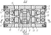
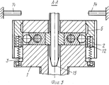
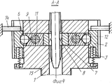
На фиг. 1 изображен патрон в разрезе, на фиг.2 - разрез Б-Б, на фиг.3 - разрез А-А в рабочем положении, на фиг.4 - разрез А-А с разжатыми кулачками. In FIG. 1 shows a cartridge in a section, FIG. 2 is a section B-B, FIG. 3 is a section AA in a working position, and FIG. 4 is a section AA with open cams.
Патрон состоит из корпуса 1. Двух сухарей 2, подпружиненных пружинами 3 и ограниченных от бокового перемещения пластинами 4, соединенных с корпусом 1 винтами 5. Каждый сухарь 2 имеет паз 6 в верхней части с внутренней стороны под шары. Внутри корпуса 1 установлены клиновидные кулачки 7, подпружиненные друг относительно друга пружинами 8. Клиновые поверхности кулачков 7 контактируют с клиновыми поверхностями ползунов 9, имеющих резьбовые отверстия с правой резьбой и клиновыми поверхностями ползунов 10, имеющих резьбовые отверстия с левой резьбой. Ползуны 9 и 10 имеют клиновую поверхность со стороны кулачков, обратную клиновой поверхности последних, и установлены в контакте этой поверхностью с клиновой поверхностью каждого из кулачков. Ползуны 9 и 10 соединены между собой винтами 11, имеющими правую и левую резьбу соответственно, а с противоположной стороны имеют конусные отверстия, под шары 12, контактирующие с сухарями 2. В корпусе 1 выполнены отверстия 13 для подхода инструмента к винтам 11 с наиболее удобной стороны. Упоры 14 находятся на протяжном станке (не показан) и расположены с двух сторон выше патрона в положении, обеспечивающем разжим кулачков 7 в верхнем крайнем положении патрона при нахождении плоской протяжки 15 в патроне без ее захвата. The cartridge consists of a
Подготовка патрона к работе. Preparing the cartridge for work.
В рабочем положении, когда сухари 2 не взаимодействуют с упорами 14, в отверстия 13 вставляется инструмент (не показан) и вращением винтов 11 устанавливается наибольший размер "В" (фиг.2). В исходном положении (фиг.4), когда упоры 14 взаимодействуют с сухарями 2, хвостовик протяжки 15 входит в патрон и они двигаются совместно до прекращения взаимодействия упоров 14 с сухарями 2. Затем совместное движение патрона и протяжки прекращается, вращают винты 11 до упора, т.е. до касания кулачками 7 хвостовика протяжки 15. После определения момента упора поворачивают каждый винт 11 в противоположную сторону на 10o...15o. Таким образом устанавливается требуемый размер "В" для данной протяжки. Далее патрон с протяжкой вновь перемещается в исходное положение и хвостовик протяжки 15 выходит из патрона. В итоге патрон готов к работе с протяжкой и размер "В" соответствует данной протяжке.In the working position, when the
Патрон работает следующим образом. The cartridge works as follows.
В исходном положении упоры 14 нажимают на сухари 2. Шары 12 попадают в пазы 6 и кулачки 7 под действием пружин 8 расходятся в противоположные стороны. Хвостовик протяжки 15 входит в патрон и далее они двигаются совместно. При этом упоры 14 перестают взаимодействовать с сухарями 2, под действием пружин 3 сухари 2 перемещаются вверх и шары 12 выходят из пазов 6. Затем шары 12 взаимодействуют с внутренней поверхностью сухарей 2 и посредством кинематической связи с ползунами 9 и 10 кулачки 7 перемещаются к хвостовику протяжки 15 и захватывают последний для выполнения рабочего хода протягивания. In the initial position, the stops 14 press on the
При холостом ходе протягивания хвостовик протяжки 15 будет захвачен кулачками 7 до момента попадания шаров 12 в пазы 6, которые смещаются к шарам 12 вследствие контакта сухарей 2 с упорами 14. Затем протяжка свободно выходит из патрона. When idling, the shank of the
При замене одной протяжки на другую с отличительными размерами хвостовика необходимо регулировать размер "В", как описано выше. When replacing one broach with another with the distinctive dimensions of the shank, it is necessary to adjust the size "B", as described above.
Как известно, при наличии эксцентриситета между осями патрона и хвостовика протяжки последний испытывает боковые нагрузки. Возникновение боковых нагрузок приводит к снижению качества протягиваемого шпоночного паза, возникновению усталостных напряжений в протяжке и даже возможна поломка хвостовика протяжки. Наличие у патрона раздельной регулировки размера "В" каждым кулачком 7 независимо друг от друга позволяет компенсировать межосевой эксцентриситет и ликвидировать боковые нагрузки на хвостовик протяжки 15 при выполнении рабочего хода протягивания. As you know, in the presence of eccentricity between the axes of the cartridge and the shank of the broach, the latter experiences lateral loads. The occurrence of lateral loads leads to a decrease in the quality of the drawn keyway, the occurrence of fatigue stresses in the broach, and even a breakage of the shank of the broach is possible. The presence of a cartridge of separate adjustment of size “B” by each
Использование предлагаемого изобретения в патронах протяжных станков позволило одним патроном выполнять несколько шпоночных пазов с применением различных протяжек. Патрон работает на вертикально-протяжном станке, результаты эксплуатации положительные. The use of the invention in cartridges of broaching machines allowed one cartridge to perform several keyways with various broaches. The cartridge works on a vertical broaching machine, the operating results are positive.
Claims (1)
Priority Applications (1)
| Application Number | Priority Date | Filing Date | Title |
|---|---|---|---|
| RU2001119072A RU2193473C1 (en) | 2001-07-11 | 2001-07-11 | Adjustable chuck for holding broach |
Applications Claiming Priority (1)
| Application Number | Priority Date | Filing Date | Title |
|---|---|---|---|
| RU2001119072A RU2193473C1 (en) | 2001-07-11 | 2001-07-11 | Adjustable chuck for holding broach |
Publications (1)
| Publication Number | Publication Date |
|---|---|
| RU2193473C1 true RU2193473C1 (en) | 2002-11-27 |
Family
ID=20251566
Family Applications (1)
| Application Number | Title | Priority Date | Filing Date |
|---|---|---|---|
| RU2001119072A RU2193473C1 (en) | 2001-07-11 | 2001-07-11 | Adjustable chuck for holding broach |
Country Status (1)
| Country | Link |
|---|---|
| RU (1) | RU2193473C1 (en) |
Citations (3)
| Publication number | Priority date | Publication date | Assignee | Title |
|---|---|---|---|---|
| SU141051A1 (en) * | 1961-02-16 | 1961-11-30 | Е.А. Гладкий | Chuck holder for gripping and holding broach |
| US4859125A (en) * | 1988-10-31 | 1989-08-22 | Crankshaft Machine Company | Helical broach puller |
| SU1540964A1 (en) * | 1987-05-20 | 1990-02-07 | Ярославский Завод Топливной Аппаратуры | Automatic check for broaching machines |
-
2001
- 2001-07-11 RU RU2001119072A patent/RU2193473C1/en not_active IP Right Cessation
Patent Citations (3)
| Publication number | Priority date | Publication date | Assignee | Title |
|---|---|---|---|---|
| SU141051A1 (en) * | 1961-02-16 | 1961-11-30 | Е.А. Гладкий | Chuck holder for gripping and holding broach |
| SU1540964A1 (en) * | 1987-05-20 | 1990-02-07 | Ярославский Завод Топливной Аппаратуры | Automatic check for broaching machines |
| US4859125A (en) * | 1988-10-31 | 1989-08-22 | Crankshaft Machine Company | Helical broach puller |
Similar Documents
| Publication | Publication Date | Title |
|---|---|---|
| US4519279A (en) | Selfcentering work-rest | |
| EP2536531B2 (en) | Machine tool and method for machining a workpiece | |
| US5292139A (en) | Clamping chuck for a machine tool, especially an automatic machine tool, and a method for preparing it | |
| DE1752510C3 (en) | Device for centric clamping of an annular workpiece on a faceplate | |
| GB2081158A (en) | Vibration threading lathe for precision screw cutting | |
| KR0173479B1 (en) | Device for removably securing a tool to a machine spindle | |
| DE69809439T2 (en) | TOOL HOLDER | |
| CN217166510U (en) | Numerical control lathe machining center | |
| DE102017110547B4 (en) | Method for clamping a component | |
| CH625449A5 (en) | ||
| US3494627A (en) | Jaw chuck | |
| EP1238730B1 (en) | Chuck | |
| EP4635657A1 (en) | Friction cone tensioning system for a machine tool, machine tool and method for machining a workpiece with a machine tool | |
| DE2852875A1 (en) | Multi-spindle drill head for simultaneous boring - operates using drive tool shaft separate from drive gear | |
| CA1288936C (en) | Nipple chuck | |
| DE2611923A1 (en) | Small dia. power operated chuck - has three weighted arms to compensate for centrifugal force on jaw operating mechanism | |
| US4479292A (en) | Polygon box tools applied to automatic screw machines | |
| RU2087237C1 (en) | Thread rolling head with flat threading dies for making ultimately fine threads (its variants) | |
| RU2060138C1 (en) | Device for reclaiming openings | |
| EP0423425B1 (en) | Collet chuck for automatic machine tools | |
| US2678825A (en) | Grip | |
| EP4491330B1 (en) | Supporting device | |
| RU2047425C1 (en) | Switch-free drill chuck | |
| RU2201847C2 (en) | Method of and device for workpiece mounting and turning | |
| RU2049606C1 (en) | Subsidiary chuck for clamping broach |
Legal Events
| Date | Code | Title | Description |
|---|---|---|---|
| MM4A | The patent is invalid due to non-payment of fees |
Effective date: 20100712 |