RU2196403C2 - Tillage module - Google Patents
Tillage module Download PDFInfo
- Publication number
- RU2196403C2 RU2196403C2 RU2001100768/13A RU2001100768A RU2196403C2 RU 2196403 C2 RU2196403 C2 RU 2196403C2 RU 2001100768/13 A RU2001100768/13 A RU 2001100768/13A RU 2001100768 A RU2001100768 A RU 2001100768A RU 2196403 C2 RU2196403 C2 RU 2196403C2
- Authority
- RU
- Russia
- Prior art keywords
- soil
- drag
- tillage
- pin
- rods
- Prior art date
Links
- 238000003971 tillage Methods 0.000 title claims abstract description 17
- 239000002689 soil Substances 0.000 claims abstract description 32
- 238000003825 pressing Methods 0.000 claims description 4
- 230000000694 effects Effects 0.000 abstract 1
- 239000000126 substance Substances 0.000 abstract 1
- 239000002344 surface layer Substances 0.000 abstract 1
- 230000006378 damage Effects 0.000 description 6
- 239000002184 metal Substances 0.000 description 4
- 238000004140 cleaning Methods 0.000 description 3
- 238000009331 sowing Methods 0.000 description 3
- 230000009418 agronomic effect Effects 0.000 description 2
- 238000005096 rolling process Methods 0.000 description 2
- 244000241257 Cucumis melo Species 0.000 description 1
- 235000015510 Cucumis melo subsp melo Nutrition 0.000 description 1
- 241000196324 Embryophyta Species 0.000 description 1
- 244000061456 Solanum tuberosum Species 0.000 description 1
- 235000002595 Solanum tuberosum Nutrition 0.000 description 1
- 230000006978 adaptation Effects 0.000 description 1
- 238000004220 aggregation Methods 0.000 description 1
- 230000002776 aggregation Effects 0.000 description 1
- 230000015572 biosynthetic process Effects 0.000 description 1
- 238000009313 farming Methods 0.000 description 1
- 239000000446 fuel Substances 0.000 description 1
- 238000009499 grossing Methods 0.000 description 1
- 238000003306 harvesting Methods 0.000 description 1
- 235000021374 legumes Nutrition 0.000 description 1
- 238000004519 manufacturing process Methods 0.000 description 1
- 210000003739 neck Anatomy 0.000 description 1
- 210000000056 organ Anatomy 0.000 description 1
- 230000035515 penetration Effects 0.000 description 1
- 235000012015 potatoes Nutrition 0.000 description 1
- 230000001105 regulatory effect Effects 0.000 description 1
- 235000013311 vegetables Nutrition 0.000 description 1
Images
Landscapes
- Agricultural Machines (AREA)
- Soil Working Implements (AREA)
Abstract
Description
Изобретение относится к почвообрабатывающим орудиям, в частности к выравнивателям поверхностного слоя почвы после ее рыхления. The invention relates to tillage implements, in particular to levelers of the surface soil layer after loosening.
Одной из операций обработки почвы, входящей в комплекс последовательно выполняемых работ, является операция выравнивания поверхности взрыхленного поля с разрушением комьев выравнивающими и прикатывающими приспособлениями, которые могут использоваться как в одномерном модульном варианте, так и в составе комбинированных агрегатов, совмещающих вспашку (рыхление), выравнивание (планирование), боронование, прикатывание. One of the tillage operations, which is part of a series of sequentially performed works, is the operation of leveling the surface of a loosened field with the destruction of clods by leveling and rolling tools, which can be used both in a one-dimensional modular version, and as part of combined units combining plowing (cultivation), leveling (planning), harrowing, rolling.
Известно выравнивающее орудие ВПН-5, 6, входящее в состав комбинированного устройства обработки почвы [1]. Оно включает раму, выравнивающие рабочие органы, бороны и разравниватели. Рабочие органы выравнивателя представляют собой шесть отрезков металлических органов, жестко закрепленных на подрамник под углом 70-90o к направлению движения, последний - к общей несущей раме орудия. Недостатком этого выравнивателя является неизменная (постоянная) нагрузка давления на поверхность почвы через раму, подрамник, уголки. Это приводит к следующему. При повышенной влажности верхнего слоя почвы происходит налипание с последующим прессованием почвы вместе с растительными остатками на рабочие органы, что влечет за собой нагорт и забивание выравнивателя. При сухом верхнем слое почвы разрушение комьев почвы, как правило, не обеспечивается. При нормальной влажности верхнего слоя почвы по зяблевой вспашке засыпание глубоких борозд, которые всегда присутствуют, не обеспечивается, что отрицательно влияет на качество посева семян, на урожайность. Для достижения нужного качества работы выравнивателя дополнительно используют, в частности, бороны или катки. Вместе с тем, если выравниватель натолкнется на посторонний предмет, что имеет место в практике, с большим заглублением в почве, то неизбежно из-за жесткости конструкции произойдет поломка рабочего органа выравнивателя.Known leveling tool VPN-5, 6, which is part of a combined soil treatment device [1]. It includes a frame, leveling tools, harrows and levelers. The working bodies of the equalizer are six pieces of metal organs, rigidly fixed to the subframe at an angle of 70-90 o to the direction of movement, the latter to the general bearing frame of the gun. The disadvantage of this equalizer is the constant (constant) pressure load on the soil surface through the frame, subframe, corners. This leads to the following. With increased humidity of the upper soil layer, sticking occurs, followed by pressing the soil together with the plant residues on the working bodies, which entails the loading and clogging of the leveler. With a dry topsoil, the destruction of clods of soil, as a rule, is not ensured. With normal moisture in the upper soil layer, it is not ensured to fall asleep during deep plowing, which are always present, which negatively affects the quality of seed sowing and yield. To achieve the desired quality of the equalizer, additionally, in particular, harrows or rollers are used. At the same time, if the equalizer runs into a foreign object, which is the case in practice, with a large penetration in the soil, then inevitably due to the rigidity of the structure, the working element of the equalizer will break.
Известен комбинированный пахотный агрегат с приспособлением ПКА-2А для выравнивания поверхности поля [2]. Он включает плуг, волокушу, каток и сцепки для них. Волокуша представляет собой металлический уголок 80•80 мм, установленный под углом к линии движения плуга посредством тяг гибких и кронштейнов. Тяги жестко прикреплены своими концами к волокуше и кронштейнам, т. е. с постоянным нерегулирующим углом. Поскольку волокуша не обеспечивает нужного разрушения комьев, выравнивания поверхности и засыпания глубоких борозд по зяблевой вспашке, поэтому агрегат дополнительно оснащается кольчатым катком, но и после катка остаются следы глубоких борозд. Known combined arable unit with adaptation PKA-2A for leveling the surface of the field [2]. It includes a plow, drag, roller and hitch for them. The draper is a metal angle of 80 • 80 mm, mounted at an angle to the line of movement of the plow by means of flexible rods and brackets. The rods are rigidly attached with their ends to the drag and brackets, i.e. with a constant non-regulating angle. Since the scraper does not provide the necessary destruction of clods, leveling the surface and falling asleep deep furrows along the plowing, so the unit is additionally equipped with a ring roller, but traces of deep furrows remain after the roller.
Наиболее близким техническим решением является выравниватель ПЛН-4-35 [3] в составе комбинированного пахотного агрегата. Он состоит из рамы, на которой смонтированы катки и выравниватели. Выравниватель состоит из швеллера металлического или доски толщиной 50 мм и шириной 200 мм, окантованной металлическим уголком, а также рычагов, шарнирно крепящихся к раме. Нижние концы рычагов жестко связаны с доской, верхние - через пружину растяжения - с рамой. Это позволяет в определенной мере оказывать воздействие выравнивателя на гребни. В этой конструкции сделана попытка создания свободных переменных нагрузок. Но поскольку задача получения нужного качества не достигается, дополнительно ввели катки с ящиками для загрузки балласта, увеличивая давление на поверхность почвы. Но при повышенной влажности по верхнему слою почвы происходит ее налипание на рабочие органы вместе с остатками растительности и дальнейшим прессованием; в результате образуются нагорты и агрегат забивается. Это требует остановки агрегата для его очистки, что связано с большими потерями рабочего времени и тяжелым ручным трудом. К тому же слишком металлоемкая конструкция и большая габаритность по длине в целом влияют на экономические показатели - производительность и расход топлива. The closest technical solution is the equalizer PLN-4-35 [3] as part of a combined arable unit. It consists of a frame on which rollers and levelers are mounted. The leveler consists of a channel of a metal or board 50 mm thick and 200 mm wide, edged with a metal corner, as well as levers pivotally attached to the frame. The lower ends of the levers are rigidly connected to the board, the upper ones, through the tension spring, to the frame. This allows to a certain extent to influence the equalizer on the ridges. This design attempts to create free variable loads. But since the task of obtaining the desired quality is not achieved, we additionally introduced rollers with boxes for loading ballast, increasing pressure on the soil surface. But with increased humidity on the upper soil layer, it sticks to the working bodies together with the remains of the vegetation and further pressing; as a result, nagorytes are formed and the unit is clogged. This requires stopping the unit to clean it, which is associated with large losses of working time and heavy manual labor. In addition, a too metal-consuming design and a large overall length affect the overall economic performance - productivity and fuel consumption.
В основу настоящего изобретения поставлены задачи создания самоочищающегося, малогабаритного и мобильного в работе орудия (почвовыравнивателя) с разрушением комьев почвы, завалом глубоких борозд, с возможностью дистанционного механизированного управления усилием, прилагаемого к волокуше принудительно в необходимых случаях. Модульное исполнение позволяет его использовать как автономно, так и в комплексе с почвообрабатывающими агрегатами. The basis of the present invention is the task of creating a self-cleaning, small-sized and mobile tool (soil leveler) with the destruction of clods of soil, blockage of deep furrows, with the possibility of remote mechanized control of the force applied to the drag by force if necessary. The modular design allows it to be used both autonomously and in combination with tillage units.
Поставленная задача решается тем, что выравниватель поверхностного слоя почвы, содержащий волокушу, гибкие тяги, связанные с волокушей, отличающийся тем, что он снабжен механизмом дистанционного управления усилием прижима волокуши к поверхности почвы, выполненного в виде платформы, на которой в подшипниковых опорах установлена с возможностью поворота ось, кулиса, которая одним концом жестко связана с осью, а другим - шарнирно со штоком силового цилиндра, рычагов, закрепленных на упомянутой оси и связанных с гибкими регулируемыми по длине тягами, противоположные концы которых соединены с подшипниковыми корпусами волокуши. The problem is solved in that the equalizer of the surface soil layer containing the drag, flexible traction associated with the drag, characterized in that it is equipped with a remote control mechanism for pressing the drag to the soil surface, made in the form of a platform on which the bearings are mounted with turning axis, the link, which is rigidly connected to the axis at one end and pivotally connected to the rod of the power cylinder at the other end; rods, opposite ends of which are connected to the bearing housing scraper.
Изобретение характеризуется тем, что волокуша выполнена в виде цилиндрической балки с мерными ребордами вдоль ее оси на наружной поверхности, в шахматном порядке по ее окружности. Посредством такого конструктивного решения стало возможным дистанционное управление работой волокуши, создающее принудительно изменяемую нагрузку на волокушу в зависимости от состояния поверхностного слоя почвы (гребни, комья, борозды) и требуемых условий планирования поверхностного слоя почвы. The invention is characterized in that the drag is made in the form of a cylindrical beam with measuring flanges along its axis on the outer surface, in a checkerboard pattern around its circumference. By means of such a constructive solution, it became possible to remote control the operation of the drag, creating a force-changing load on the drag depending on the state of the surface soil layer (ridges, clods, grooves) and the required planning conditions for the surface soil layer.
Изменение нагрузки достигается изменением углов подъема, образованных между линиями горизонта обрабатываемого поля и гибкими тягами волокуши. Изменение углов подъема в свою очередь достигается поворотом оси, смонтированной на платформе, посредством кулисы, связанной шарнирно с силовым цилиндром, управляемым непосредственно из кабины трактора. Благодаря принципиальному изменению нагрузки на волокушу достигается нужное качество сглаживания гребней, разрушения комьев и частичного завала (засыпания) более глубоких борозд. Полное засыпание глубоких борозд достигается разностью длин тяг, которые образуют угол схода почвы относительно планируемой поверхности поля. Вращение волокуши в подшипниках обеспечивает ее самоочищение и исключает образование нагортов. The change in load is achieved by changing the lifting angles formed between the horizon lines of the treated field and the flexible traction of the drag. Changing the lifting angles, in turn, is achieved by turning the axis mounted on the platform, through the wings, pivotally connected to the power cylinder, controlled directly from the tractor cab. Due to the fundamental change in the load on the drag, the desired quality of smoothing ridges, destruction of lumps and partial blockage (falling asleep) of deeper furrows is achieved. Complete falling asleep of deep furrows is achieved by the difference in the lengths of the rods, which form the angle of descent of the soil relative to the planned field surface. The rotation of the drag in the bearings ensures its self-cleaning and eliminates the formation of deposits.
Регулируемое усилие, прикладываемое к волокуше, позволило исключить использование дополнительно устанавливаемых за выравнивателем катков с балластным грузом, различных борон и других приспособлений. Это один из главных экономических показателей в агрегатировании почвообрабатывающих комплексов. К тому же предложенная конструкция придала агрегату повышенную маневренность из-за значительного сокращения габаритности по длине, дала возможность работать на повышенных скоростях, добиться качества рыхления (вспашки) почвы с соблюдением агрономических требований, независимо от состава и содержания обрабатываемого поля, упразднить ненужные затраты на производство в сельхозмашиностроении дополнительных приспособлений. Для регионов рискованного земледелия, в частности Северного Кавказа, почвообрабатывающий модуль повышает качество мульчирования поверхностно обработанного слоя почвы, что непосредственно влияет на влагосбережение, а значит - на обеспечение урожайности возделываемых культур - зерново-бобовых, овощных, бахчевых, пропашных и картофеля. Adjustable force applied to the drag, made it possible to exclude the use of rollers with ballast weights additionally installed behind the equalizer, various harrows and other devices. This is one of the main economic indicators in the aggregation of tillage complexes. In addition, the proposed design gave the unit increased maneuverability due to a significant reduction in overall length, made it possible to work at higher speeds, to achieve the quality of loosening (plowing) of the soil in compliance with agronomic requirements, regardless of the composition and content of the treated field, to eliminate unnecessary production costs in agricultural machinery for additional devices. For risky farming regions, in particular, the North Caucasus, the tillage module improves the quality of mulching of the surface treated soil layer, which directly affects moisture conservation, and therefore, ensures the yield of cultivated crops - legumes, vegetables, melons, row crops and potatoes.
Предложенная конструкция прошла испытания в составе послойно-почвообрабатывающего агрегата (см. заявку 99109495 от 11.05.99, по которой принято решение о выдаче патента) на полях Краснодарского края с различным их содержанием и при различных погодных условиях. Акт по результатам испытания прилагается. The proposed design has been tested as part of a layered tillage unit (see application 99109495 of 05/11/99, according to which a decision was made to grant a patent) in the fields of the Krasnodar Territory with different contents and under different weather conditions. The test report is attached.
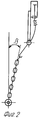
На чертежах схематически изображен почвообрабатывающий модуль. Вид сверху - фиг. 1, вид сбоку - фиг. 2. The drawings schematically depict a tillage module. Top view - FIG. 1, side view - FIG. 2.
Почвообрабатывающий модуль, одновременно производящий выравнивание поверхностного слоя почвы с разрушением комьев и завалов глубоких борозд после рыхления (вспышки), выполнен в виде платформы 1, на которой смонтированы подшипниковые опоры 2 и 3, силовой цилиндр 4, например гидравлический; в опорах 2 и 3 установлена с возможностью поворота ось 5, на которой закреплена дугообразная кулиса 6, шарнирно связанная со штоком 7 цилиндра 4. По краям оси 5 закреплены жестко рычаги 8 и 9, связанные с гибкими тягами 10 и 11, выполненными, например, из круглозвенных цепей. Волокуша 12 установлена в подшипники 13 и 14, смонтированные известным способом в корпусах, к которым крепятся тяги 10 и 11. Волокуша 12 выполнена в виде цилиндрической балки с шейками на концах под подшипники. На наружной поверхности балки вдоль ее оси имеются мерные реборды 15, расположенные по окружности в шахматном порядке. Тяги 10 и 11 каждая в отдельности могут регулироваться по длине, для чего на рычагах 8 и 9 предусмотрены крючья. Шарнирная связь штока 7 с кулисой 6 может быть выполнена в виде серьги и соединительного пальца или другим известным способом. The tillage module, simultaneously leveling the surface soil layer with the destruction of clods and blockages of deep grooves after loosening (flash), is made in the form of a platform 1, on which bearing bearings 2 and 3 are mounted, a power cylinder 4, for example, a hydraulic one; in the supports 2 and 3, the axis 5 is mounted for rotation, on which an arc-shaped link 6 is fixed, pivotally connected to the rod 7 of the cylinder 4. At the edges of the axis 5, levers 8 and 9 are rigidly fixed, connected with flexible rods 10 and 11, made, for example, from round link chains. The drag 12 is installed in bearings 13 and 14, mounted in a known manner in the housings to which the rods 10 and 11 are attached. The drag 12 is made in the form of a cylindrical beam with necks at the ends under the bearings. On the outer surface of the beam along its axis there are measuring flanges 15, located around the circumference in a checkerboard pattern. The rods 10 and 11 individually can be adjusted in length, for which hooks are provided on the levers 8 and 9. The hinge connection of the rod 7 with the link 6 can be made in the form of an earring and a connecting finger or in another known manner.
Почвообрабатывающий модуль работает следующим образом. К известному послойно почвообрабатывающиму агрегату (на чертеже не показан) крепится на раму платформа 1 выравнивателя, гидроцилиндр 4 шлангами связывается с гидросистемой трактора для получения требуемого усилия прижима волокуши к поверхности почвы, тяги 10 и 11 предварительно устанавливаются на угол подъема β к поверхности почвы, который определяется визуально в зависимости от содержания поля и состояния почвы. Подбирается угол схода α по направлению движения волокуши 12, обеспечивающий засыпание борозд и сглаживание гребней на взрыхленной почве путем изменения длины одной из тяг 10 и 11. При движении агрегата волокуша 12, установленная под углом схода α к линии движения с отрегулированными углами подъема β давлением на поверхности почвы, разрушает комья, засыпает борозды и планирует поверхность почвы с одновременным самоочищением. Таким образом достигается соответствие взрыхленной и спланированной поверхности почвы агрономическим требованиям. Tillage module works as follows. To the well-known layer-by-layer tillage unit (not shown in the drawing), the equalizer platform 1 is attached to the frame, the hydraulic cylinder 4 is connected by hoses to the hydraulic system of the tractor to obtain the required clamping force of the drag to the soil surface, rods 10 and 11 are pre-set to the angle of elevation β to the soil surface, which determined visually depending on the field content and soil condition. The vanishing angle α is selected in the direction of movement of the drag 12, which ensures that the furrows fall asleep and the ridges are smoothed out on loosened soil by changing the length of one of the rods 10 and 11. When the aggregate moves, the drag 12 mounted at the vanishing angle α to the movement line with adjusted elevation angles β surface of the soil, destroys clods, falls asleep furrows and plans the surface of the soil with simultaneous self-cleaning. Thus, the compliance of the loosened and planned soil surface with agronomic requirements is achieved.
Источники информации
1. В.Н. Дроздов, В.Ф. Кондеев. Комбинированные почвобрабатывающие посевные машины. М.: Нива России, 1992 г., стр. 53-54, рис. 20.Sources of information
1. V.N. Drozdov, V.F. Kondeev. Combined tillage sowing machines. M .: Niva of Russia, 1992, pp. 53-54, Fig. 20.
2. Там же. Стр. 30-31, рис.13. 2. There. Page 30-31, Fig. 13.
3. Там же. Стр. 32-33, рис.14 (прототип)
4. SU 519154, А 01 В 49/02, 30.06.76.3. There. Page 32-33, Fig. 14 (prototype)
4. SU 519154, A 01 B 49/02, 06.30.76.
5. SU 302059, А 01 В 49/02, 28.04.71. 5. SU 302059, A 01 B 49/02, 04/28/71.
6. Мацепуро О. М. Механизация предпосевного выравнивания почвы. Урожай 1987 г. 6. Matsepuro OM. Mechanization of pre-sowing soil leveling. Harvest 1987
7. П.А. Забазный, Ю.П. Буряков, Ю.Г. Карцев и др. Краткий справочник агронома. М.: Колос, 1983 г., стр. 13. 7. P.A. Zabazny, Yu.P. Buryakov, Yu.G. Kartsev et al. Agronomist's quick reference. M .: Kolos, 1983, p. 13.
Claims (2)
Priority Applications (1)
| Application Number | Priority Date | Filing Date | Title |
|---|---|---|---|
| RU2001100768/13A RU2196403C2 (en) | 2001-01-09 | 2001-01-09 | Tillage module |
Applications Claiming Priority (1)
| Application Number | Priority Date | Filing Date | Title |
|---|---|---|---|
| RU2001100768/13A RU2196403C2 (en) | 2001-01-09 | 2001-01-09 | Tillage module |
Publications (2)
| Publication Number | Publication Date |
|---|---|
| RU2001100768A RU2001100768A (en) | 2002-12-27 |
| RU2196403C2 true RU2196403C2 (en) | 2003-01-20 |
Family
ID=20244635
Family Applications (1)
| Application Number | Title | Priority Date | Filing Date |
|---|---|---|---|
| RU2001100768/13A RU2196403C2 (en) | 2001-01-09 | 2001-01-09 | Tillage module |
Country Status (1)
| Country | Link |
|---|---|
| RU (1) | RU2196403C2 (en) |
Cited By (2)
| Publication number | Priority date | Publication date | Assignee | Title |
|---|---|---|---|---|
| RU2383122C2 (en) * | 2008-03-24 | 2010-03-10 | Федеральное государственное образовательное учреждение высшего профессионального образования "Брянская государственная сельскохозяйственная академия" | Method for preparation of soil for potato plant |
| RU233355U1 (en) * | 2025-01-17 | 2025-04-16 | Федеральное Государственное Бюджетное Образовательное Учреждение Высшего Образования "Дальневосточный Государственный Аграрный Университет" | Device for automatic adjustment of load on soil-cultivating roller |
Citations (4)
| Publication number | Priority date | Publication date | Assignee | Title |
|---|---|---|---|---|
| SU519154A1 (en) * | 1974-11-13 | 1976-06-30 | Всесоюзный Ордена Трудового Красного Знамени Научно-Исследовательский Институт Механизации Сельского Хозяйства | Combined tillage implement |
| SU873903A1 (en) * | 1980-03-17 | 1981-10-23 | Белорусская Ордена Трудового Красного Знамени Сельскохозяйственная Академия | Soil microrelief leveller |
| RU2053615C1 (en) * | 1993-04-23 | 1996-02-10 | Всероссийский научно-исследовательский и проектно-технологический институт механизации и электрификации сельского хозяйства | Combination soil-tilling unit |
| RU2148897C1 (en) * | 1999-09-29 | 2000-05-20 | Бурбель Анатолий Федорович | Tillage unit |
-
2001
- 2001-01-09 RU RU2001100768/13A patent/RU2196403C2/en not_active IP Right Cessation
Patent Citations (4)
| Publication number | Priority date | Publication date | Assignee | Title |
|---|---|---|---|---|
| SU519154A1 (en) * | 1974-11-13 | 1976-06-30 | Всесоюзный Ордена Трудового Красного Знамени Научно-Исследовательский Институт Механизации Сельского Хозяйства | Combined tillage implement |
| SU873903A1 (en) * | 1980-03-17 | 1981-10-23 | Белорусская Ордена Трудового Красного Знамени Сельскохозяйственная Академия | Soil microrelief leveller |
| RU2053615C1 (en) * | 1993-04-23 | 1996-02-10 | Всероссийский научно-исследовательский и проектно-технологический институт механизации и электрификации сельского хозяйства | Combination soil-tilling unit |
| RU2148897C1 (en) * | 1999-09-29 | 2000-05-20 | Бурбель Анатолий Федорович | Tillage unit |
Non-Patent Citations (1)
| Title |
|---|
| ДРОЗДОВ В.Н. И КАНДЕЕВ В.Ф. Комбинированные почвообрабатывающие и посевные машины. - М.: Нива России, 1992, с.32-33, рис.14. * |
Cited By (3)
| Publication number | Priority date | Publication date | Assignee | Title |
|---|---|---|---|---|
| RU2383122C2 (en) * | 2008-03-24 | 2010-03-10 | Федеральное государственное образовательное учреждение высшего профессионального образования "Брянская государственная сельскохозяйственная академия" | Method for preparation of soil for potato plant |
| RU233355U1 (en) * | 2025-01-17 | 2025-04-16 | Федеральное Государственное Бюджетное Образовательное Учреждение Высшего Образования "Дальневосточный Государственный Аграрный Университет" | Device for automatic adjustment of load on soil-cultivating roller |
| RU241402U1 (en) * | 2025-11-21 | 2026-02-24 | Федеральное Государственное Бюджетное Образовательное Учреждение Высшего Образования "Дальневосточный Государственный Аграрный Университет" | Corrector-regulator of the loosening depth of the surface soil layer after the passage of the seeder |
Similar Documents
| Publication | Publication Date | Title |
|---|---|---|
| US4054007A (en) | Row-crop tillage and treating device | |
| US5862764A (en) | Method and apparatus for a floating frame field harrow | |
| EP0407896B1 (en) | Groundworking machine for row cultures | |
| US5318134A (en) | Irrigation furrow and raised seed bed forming machine | |
| Søgaard | Automatic control of a finger weeder with respect to the harrowing intensity at varying soil structures | |
| CZ307814B6 (en) | Potato harvester working unit and cultivator with this working unit | |
| RU2196403C2 (en) | Tillage module | |
| RU2352095C1 (en) | Combined unit for soil preparation and applying liquid organic fertilisers | |
| RU2256312C1 (en) | Tillage tool | |
| Tullberg | Developments in mechanization technology: controlled traffic farming | |
| RU2239296C2 (en) | Tilling-and-seeding unit | |
| RU2101892C1 (en) | Cultivating implement | |
| RU2193832C2 (en) | Agricultural unit for surface tillage of soil | |
| KR100746604B1 (en) | Agricultural vinyl coating machine | |
| RU2172576C1 (en) | Digging out clip | |
| RU2110165C1 (en) | Slit cutting apparatus | |
| RU20813U1 (en) | COMBINED SOIL PROCESSING UNIT | |
| RU2091998C1 (en) | Tillage unit | |
| RU2048712C1 (en) | Mouldboard tine | |
| RU216042U1 (en) | CULTIVATOR FOR TREATMENT OF PROTECTIVE ZONES OF POTATO GRIDGES | |
| Raffaelli et al. | Physical weed control in protected leaf-beet in central Italy | |
| RU2045144C1 (en) | Tillage device | |
| RU2227965C1 (en) | Method and apparatus for cultivation of cucurbitaceous crops | |
| RU211831U1 (en) | Bed former for the cultivation of garden strawberries | |
| RU19988U1 (en) | UNIVERSAL UNIT FOR TILLING SOIL |
Legal Events
| Date | Code | Title | Description |
|---|---|---|---|
| MM4A | The patent is invalid due to non-payment of fees |
Effective date: 20040110 |