RU2199480C2 - Feeder for delivering viscous difficult-to-flow materials - Google Patents
Feeder for delivering viscous difficult-to-flow materials Download PDFInfo
- Publication number
- RU2199480C2 RU2199480C2 RU2000130347A RU2000130347A RU2199480C2 RU 2199480 C2 RU2199480 C2 RU 2199480C2 RU 2000130347 A RU2000130347 A RU 2000130347A RU 2000130347 A RU2000130347 A RU 2000130347A RU 2199480 C2 RU2199480 C2 RU 2199480C2
- Authority
- RU
- Russia
- Prior art keywords
- conveyor
- auger
- shaft
- pulser
- feeder
- Prior art date
Links
- 239000000463 material Substances 0.000 title claims abstract description 30
- 230000001681 protective effect Effects 0.000 claims abstract description 5
- 230000010355 oscillation Effects 0.000 claims description 2
- 230000000694 effects Effects 0.000 abstract description 4
- 239000000126 substance Substances 0.000 abstract description 3
- 238000010276 construction Methods 0.000 abstract description 2
- 230000012173 estrus Effects 0.000 description 4
- 239000013590 bulk material Substances 0.000 description 2
- 238000009434 installation Methods 0.000 description 2
- 238000012271 agricultural production Methods 0.000 description 1
- 238000005056 compaction Methods 0.000 description 1
- 239000000470 constituent Substances 0.000 description 1
- 230000006378 damage Effects 0.000 description 1
- 239000002245 particle Substances 0.000 description 1
- 230000000737 periodic effect Effects 0.000 description 1
Images
Landscapes
- Screw Conveyors (AREA)
- Filling Or Emptying Of Bunkers, Hoppers, And Tanks (AREA)
Abstract
Description
Изобретение относится к перегрузке сильносвязных плохосыпучих материалов и может быть использовано для равномерной подачи материала в технологические установки и аппараты, применяемые в сельскохозяйственном производстве, в химической, пищевой, строительной промышленности и других отраслях народного хозяйства. The invention relates to the overload of strongly bonded low-flowing materials and can be used to uniformly supply material to technological installations and apparatuses used in agricultural production, in the chemical, food, construction industry and other sectors of the national economy.
Известен питатель для подачи сильносвязных плохосыпучих материалов, содержащий бункер с выпускной течкой, установленный под ней конвейер с головным и натяжным барабанами, охватывающий конвейер защитный кожух с приемным коробом в зоне головного барабана, и установленный в кожухе перед течкой бункера регулятор толщины слоя подаваемого материала (авт. свид. СССР 963943, кл. В 65 G 65/30, 1979). A well-known feeder for supplying highly-bonded low-flowing materials, containing a hopper with an exhaust chute, a conveyor with a head and tension drums mounted under it, a protective casing covering the conveyor with a receiving box in the head drum zone, and a layer thickness regulator installed in the casing before the chute estrus (automatic certificate of the USSR 963943, class B 65 G 65/30, 1979).
Недостаток известной конструкции - объемная масса сильносвязных плохосыпучих материалов при неорганизованной их подачи из бункера поступает к месту разгрузки неравномерным потоком, что снижает эксплуатационные характеристики питателя. A disadvantage of the known design is that the bulk mass of strongly bonded low-flowing materials, when they are unorganized from the hopper, enters the discharge point in an uneven flow, which reduces the operational characteristics of the feeder.
Наиболее близким по технической сущности и достигаемому результату к предлагаемому изобретению является питатель для подачи сильносвязных плохосыпучих материалов, содержащий бункер с выпускной течкой и регулятором толщины слоя подаваемого материала, смонтированный под ней конвейер с головным и натяжным барабанами, охватывающий конвейер защитный кожух с приемным коробом и установленный на приводном валу шнек, причем последний расположен над головным барабаном конвейера в зоне осыпания материала (авт. свид. СССР 1426913, кл. В 65 G 65/30, 1987). The closest in technical essence and the achieved result to the proposed invention is a feeder for supplying highly bonded low-flowing materials, containing a hopper with an outlet chute and a regulator of the thickness of the feed material layer, a conveyor mounted under it with a head and tension drums, a protective casing covering the conveyor with a receiving box and installed auger on the drive shaft, the latter being located above the conveyor head drum in the zone of material shedding (ed. certificate of the USSR 1426913, class B 65 G 65/30, 1987).
Схемно-конструктивное решение указанного питателя при динамической активности воздействия со стороны спиральных витков шнека на поток перемещаемого материала в зоне разгрузки позволяет несколько снизить неравномерность подачи материала с низкой сыпучестью, связанностью его компонентов и повышенным уплотнением. The schematic design solution of the specified feeder with dynamic activity of the spiral side turns of the screw on the flow of the transported material in the unloading zone allows to somewhat reduce the unevenness of the material supply with low flowability, cohesion of its components and increased compaction.
Однако практика эксплуатации такого питателя показала, что отсутствие режима подвижности шнека в угловых направлениях при вращательном его движении не в полной мере позволяет реализовать положительно доминирующий фактор - объемный и сдвиговый характер деформации материала при знакопеременных силовых воздействиях со стороны спиральных витков шнека и во взаимосвязи с периодическими изменениями сил сопротивления перегружаемой массы материала в соответствии с фазами ее деформации, разрушения связанности и рыхления. However, the practice of operating such a feeder showed that the lack of auger mobility in angular directions during its rotational movement does not fully allow the positively dominant factor to be realized - the volumetric and shear nature of the material deformation under alternating force effects from the spiral turns of the auger and in conjunction with periodic changes resistance forces of the overloaded mass of material in accordance with the phases of its deformation, fracture of bonding and loosening.
Задача предлагаемого изобретения - улучшение эксплуатационно-технологических характеристик питателя за счет кинематических параметров относительных движений шнека и силового поля воздействия его спиральных витков на поток перегружаемого материала. The objective of the invention is to improve the operational and technological characteristics of the feeder due to the kinematic parameters of the relative movements of the screw and the force field of the impact of its spiral turns on the flow of overloaded material.
Поставленная задача решается тем, что в питателе для подачи сильносвязных плохосыпучих материалов, содержащем бункер с выпускной течкой, смонтированный под ней конвейер с головным и натяжным барабанами, охватывающий конвейер защитный кожух с приемным коробом и установленный на приводном валу шнек, причем последний расположен над головным барабаном конвейера в зоне осыпания материала, согласно изобретению шнек со стороны привода снабжен последовательно установленными на его валу импульсатором крутильных колебаний и инерционным механизмом. При этом импульсатор крутильных колебаний шнека выполнен в виде планетарно-зубчатого механизма с центральным зубчатым колесом и контактирующих с ним смонтированных на водиле противофазно неуравновешенных сателлитов, причем водило кинематически связано с валом шнека, инерционный механизм установлен на валу шнека и выполнен в виде размещенного в корпусе кривошипа, соединенного посредством противоположно размещенных шатунов с ползунами, смонтированными в направляющих и связанными с упругими элементами, закрепленными на корпусе механизма. The problem is solved in that in a feeder for supplying highly-bonded low-flowing materials containing a hopper with an outlet heat, a conveyor with a head and tension drums mounted under it, a protective cover covering the conveyor with a receiving box and a screw mounted on the drive shaft, the latter being located above the head drum conveyor in the zone of material shedding, according to the invention, the auger on the drive side is equipped with a torsional vibration pulser and an inertial fur ism. In this case, the auger torsion oscillator is made in the form of a planetary-gear mechanism with a central gear and contacting mounted on the carrier antiphase unbalanced satellites, the carrier being kinematically connected with the screw shaft, the inertial mechanism mounted on the screw shaft and made in the form of a crank placed in the housing connected by means of oppositely placed connecting rods with sliders mounted in guides and connected with elastic elements fixed to a mechanical housing ism.
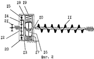
На фиг. 1 схематично показан питатель для подачи сильносвязных плохосыпучих материалов; на фиг. 2 - шнек с приводом, установленный над головным барабаном конвейера. In FIG. 1 schematically shows a feeder for supplying highly bonded low-bulk materials; in FIG. 2 - auger with a drive mounted above the head drum of the conveyor.
Питатель для подачи сильносвязных плохосыпучих материалов содержит расходный бункер 1 с выгрузной течкой 2 и смонтированный под ней конвейер с головным 3 и натяжным 4 барабанами, огибаемые бесконечной транспортерной лентой 5, грузонесущая ветвь которой лежит на поддерживающих роликах 6, при этом выгрузная течка бункера снабжена регулятором 7 толщины слоя подаваемого материала, выполненного в виде шиберной заслонки. Конвейер заключен в кожух 8, переходящий в приемный короб 9, в котором над головным барабаном 3 у границы осыпания материала с ленты питателя установлен на приводном валу 10 шнек 11. При этом шнек содержит два участка, расходящихся от центра спиральных витков с левой и правой навивками. The feeder for supplying highly-bonded low-flowing materials contains a feed hopper 1 with unloading estrus 2 and a conveyor mounted under it with a head 3 and tension 4 reels, enveloped by an endless conveyor belt 5, the load-bearing branch of which lies on the supporting rollers 6, while the unloading estrus of the hopper is equipped with a regulator 7 the thickness of the layer of feed material made in the form of a slide gate. The conveyor is enclosed in a casing 8, passing into a receiving box 9, in which a screw 11 is installed on the drive shaft 10 above the head drum 3 at the boundary of material sprinkling from the feeder belt. In this case, the screw contains two sections diverging from the center of the spiral turns with left and right coils .
Головной барабан 3 кинематически связан с приводом (не показан), обеспечивающим постоянную, либо регулируемую скорость движения транспортерной ленты 5 конвейера. Привод шнека 11 осуществляется либо от вала барабана питателя, либо автономно от электродвигателя через редуктор. The head drum 3 is kinematically connected with a drive (not shown), providing a constant or adjustable speed of the conveyor belt 5 of the conveyor. The drive of the screw 11 is carried out either from the shaft of the drum of the feeder, or independently from the electric motor through the gearbox.
Шнек со стороны привода снабжен последовательно установленными на валу 10 импульсатором крутильных колебаний и инерционным механизмом. Импульсатор крутильных колебаний выполнен в виде плане-тарно-зубчатого механизма, содержащего корпус, центральное зубчатое колесо 12, и находящихся с ним в зацеплении диаметрально расположенных на водиле 13 сателлитов 14 с противофазно неуравновешенными дебалансами 15. Водило 13 кинематически связано с валом 10 шнека 11. The auger on the drive side is equipped with a torsion oscillator and an inertial mechanism sequentially mounted on the shaft 10. The torsional vibration pulser is made in the form of a planetary-gear mechanism containing a housing, a
Инерционный механизм, установленный на валу шнека, выполнен в виде кривошипа, с которым соединены шатуны 16, а с последним связаны ползуны 17, при этом ползуны смонтированы в направляющих 18 и соединены с упругими элементами 19, закрепленными на неподвижном корпусе 20 механизма. The inertial mechanism mounted on the screw shaft is made in the form of a crank, to which the connecting
Питатель работает следующим образом. The feeder operates as follows.
Материал из бункера 1 через течку 2 поступает на грузонесущую поверхность ленты 5 конвейера и движется к приемному коробу 9. Перед осыпанием в приемный короб поток материала вступает в контакт со шнеком 11, который от привода через шестерню 21 получает вращательное движение. При этом вращение от привода на вал 10 шнека 11 осуществляется через импульсатор крутильных колебаний, выполненный в виде планетарно-зубчатого механизма, ведущее центральное зубчатое колесо 12 которого передает вращение сателлитам 14. Противофазная неуравновешенность сателлитов 14 дебалансами 15 вызывает на водило 13 знакопеременный вращающий момент - его крутильные колебания, которые передаются валу 10 шнека. При этом размах крутильных колебаний ограничивается линейной деформацией упругих элементов 19, которые попеременно сжимаются - разжимаются от поворота кривошипа, движения шатунов 16 и ползунов 17, скользящих по направляющим 18. Деформация упругих элементов 19 позволяет создать размах крутильных колебаний вала 10 и соответственно шнека 11 до 90o без применения ускоряющих механических передач. Оптимальность работы инерционного механизма предусматривает противоположное расположение направляющих 18.Material from the hopper 1 through the estrus 2 enters the load-bearing surface of the conveyor belt 5 and moves to the receiving box 9. Before shedding into the receiving box, the material flow comes into contact with the screw 11, which receives rotational movement from the drive through the gear 21. In this case, the rotation from the drive to the shaft 10 of the screw 11 is carried out through a torsional vibration pulser made in the form of a planetary gear mechanism, the leading
Таким образом, вал 10 с жестко закрепленным шнеком 11 совершает, помимо вращательного движения вокруг своей оси, дополнительно еще и угловые колебания. Импульсные угловые колебания шнека и знакопеременные силовые воздействия его спиральных витков на поток перемещаемого материала в зоне головного барабана ослабляют структуру локально-слежавшихся масс сыпучего материала и способствуют интенсивному разрушению связанности составляющих его частиц и слоев, обеспечивая при этом наиболее эффективное рыхление объемной массы материала и ее равномерное рассредоточение по ширине питателя. Разрыхленный материал проходит между шнеком 11 и транспортерной лентой на головном барабане 3 и далее сбрасывается в течку приемного короба 9, сохраняя при этом равномерную линию схода материала с поверхности ленты при огибании барабана питателя. Thus, the shaft 10 with the rigidly fixed screw 11 performs, in addition to the rotational movement around its axis, also angular oscillations. Impulse angular vibrations of the screw and alternating force effects of its spiral turns on the flow of the transported material in the head drum zone weaken the structure of locally packed masses of bulk material and contribute to the intensive destruction of the cohesion of its constituent particles and layers, while ensuring the most effective loosening of the bulk material mass and its uniform dispersal across the width of the feeder. Loosened material passes between the screw 11 and the conveyor belt on the head drum 3 and then is discharged into the heat of the intake box 9, while maintaining a uniform line of descent of the material from the surface of the belt when the feeder drum is enveloped.
Равномерная подача материала через перегрузочные устройства в технологические установки и аппараты, в свою очередь, улучшает эксплуатационно-технологические характеристики питателя при перегрузке и дозировании сильносвязных плохосыпучих материалов, в том числе имеющих в своей структуре волокнистые включения. A uniform supply of material through reloading devices to technological installations and devices, in turn, improves the operational and technological characteristics of the feeder during overloading and dosing of highly bonded low-flowing materials, including those with fibrous inclusions in their structure.
Claims (1)
Priority Applications (1)
| Application Number | Priority Date | Filing Date | Title |
|---|---|---|---|
| RU2000130347A RU2199480C2 (en) | 2000-12-04 | 2000-12-04 | Feeder for delivering viscous difficult-to-flow materials |
Applications Claiming Priority (1)
| Application Number | Priority Date | Filing Date | Title |
|---|---|---|---|
| RU2000130347A RU2199480C2 (en) | 2000-12-04 | 2000-12-04 | Feeder for delivering viscous difficult-to-flow materials |
Publications (2)
| Publication Number | Publication Date |
|---|---|
| RU2000130347A RU2000130347A (en) | 2002-11-10 |
| RU2199480C2 true RU2199480C2 (en) | 2003-02-27 |
Family
ID=20242914
Family Applications (1)
| Application Number | Title | Priority Date | Filing Date |
|---|---|---|---|
| RU2000130347A RU2199480C2 (en) | 2000-12-04 | 2000-12-04 | Feeder for delivering viscous difficult-to-flow materials |
Country Status (1)
| Country | Link |
|---|---|
| RU (1) | RU2199480C2 (en) |
Cited By (1)
| Publication number | Priority date | Publication date | Assignee | Title |
|---|---|---|---|---|
| CN107010384A (en) * | 2017-05-27 | 2017-08-04 | 河南中业重工机械有限公司 | The anti-stick feeding device of New type detachable |
Citations (4)
| Publication number | Priority date | Publication date | Assignee | Title |
|---|---|---|---|---|
| US3473702A (en) * | 1966-10-31 | 1969-10-21 | Arvid A Molitor | Vibrating feeder |
| SU1426913A1 (en) * | 1987-03-30 | 1988-09-30 | Сибирский Филиал Всесоюзного Научно-Исследовательского Теплотехнического Института Им.Ф.Э.Дзержинского | Feeder for cohesive semiloose materials |
| RU2009970C1 (en) * | 1989-09-05 | 1994-03-30 | Сибирский филиал Всероссийского научно-исследовательского теплотехнического института | Device for loose material feeding |
| RU2021961C1 (en) * | 1989-09-05 | 1994-10-30 | Сибирский филиал Всероссийского теплотехнического научно-исследовательского института | Loose material feeding device |
-
2000
- 2000-12-04 RU RU2000130347A patent/RU2199480C2/en active
Patent Citations (4)
| Publication number | Priority date | Publication date | Assignee | Title |
|---|---|---|---|---|
| US3473702A (en) * | 1966-10-31 | 1969-10-21 | Arvid A Molitor | Vibrating feeder |
| SU1426913A1 (en) * | 1987-03-30 | 1988-09-30 | Сибирский Филиал Всесоюзного Научно-Исследовательского Теплотехнического Института Им.Ф.Э.Дзержинского | Feeder for cohesive semiloose materials |
| RU2009970C1 (en) * | 1989-09-05 | 1994-03-30 | Сибирский филиал Всероссийского научно-исследовательского теплотехнического института | Device for loose material feeding |
| RU2021961C1 (en) * | 1989-09-05 | 1994-10-30 | Сибирский филиал Всероссийского теплотехнического научно-исследовательского института | Loose material feeding device |
Cited By (1)
| Publication number | Priority date | Publication date | Assignee | Title |
|---|---|---|---|---|
| CN107010384A (en) * | 2017-05-27 | 2017-08-04 | 河南中业重工机械有限公司 | The anti-stick feeding device of New type detachable |
Similar Documents
| Publication | Publication Date | Title |
|---|---|---|
| US5131525A (en) | Vibratory conveyor | |
| US2144382A (en) | Low head vibrating screen | |
| US5762176A (en) | Belt driven vibratory apparatus | |
| US3287983A (en) | Variable force oscillator | |
| US4527747A (en) | Method and vibratory chute for treating goods | |
| US11285511B2 (en) | Vibration generating mechanism for a vibrating screen box | |
| US5301844A (en) | Dry solids materials feeder with vibrating mechanism and a method of vibrating various component parts of the feeder | |
| RU2301005C2 (en) | Belt conveyor for transportation of tobacco materials | |
| RU2191729C2 (en) | Feeder for delivering coherent hard-to-flow materials | |
| US2684754A (en) | Vibratory conveyer | |
| US4662306A (en) | Fluffer mechanism for breading machine | |
| RU2238896C2 (en) | Device for supplying strongly bonded difficult-to-pour materials | |
| RU2294890C1 (en) | Feeder for delivering cohesive poorly flowing materials | |
| US2771179A (en) | Oscillating feeders | |
| RU2147289C1 (en) | Feeder-mixer | |
| US972761A (en) | Feeding device. | |
| US2688473A (en) | Arrangement for mixing and conveying plaster or the like | |
| RU2166366C1 (en) | Grinding device | |
| US3122930A (en) | Vibrating mechanism and unbalancing rotor | |
| RU2503606C1 (en) | Screw conveyor | |
| CH642283A5 (en) | MECHANICAL RUETTLER WITH DIRECTIONALITY AND ITS USE. | |
| RU2153919C1 (en) | Air cleaner | |
| RU2066289C1 (en) | Hopper for loose materials | |
| RU1787648C (en) | Bulk material mixing and discharging device | |
| RU2000130347A (en) | NUTRITION FEEDER |