RU2201059C2 - Instrument for investigating centrifuges of bulk material spreading units - Google Patents
Instrument for investigating centrifuges of bulk material spreading units Download PDFInfo
- Publication number
- RU2201059C2 RU2201059C2 RU2001111104/13A RU2001111104A RU2201059C2 RU 2201059 C2 RU2201059 C2 RU 2201059C2 RU 2001111104/13 A RU2001111104/13 A RU 2001111104/13A RU 2001111104 A RU2001111104 A RU 2001111104A RU 2201059 C2 RU2201059 C2 RU 2201059C2
- Authority
- RU
- Russia
- Prior art keywords
- cell
- bulk material
- instrument
- investigating
- ring
- Prior art date
Links
Images
Landscapes
- Catching Or Destruction (AREA)
Abstract
Description
Изобретение относится к сельскохозяйственному машиностроению, в частности к приборам для исследования центробежных аппаратов разбрасывателей сыпучих материалов, например минеральных удобрений. The invention relates to agricultural machinery, in particular to devices for the study of centrifugal apparatus of spreaders of bulk materials, for example mineral fertilizers.
Известен прибор для исследования центробежных аппаратов разбрасывателей сыпучих материалов, выполненный в виде кольца с закрепленными внутри него тонкими вертикальными перегородками, образующими с внутренней стороны кольца ячейки (см. авт. свид. СССР 214897, А 01 С 15/00, 1967). При помощи прибора можно в стационарных условиях экспериментально исследовать центробежные аппараты при разработке перспективных конструкций разбрасывателей сыпучих материалов. A known device for the study of centrifugal devices of spreaders of bulk materials, made in the form of a ring with thin vertical partitions fixed inside it, forming on the inside of the cell ring (see ed. Certificate of the USSR 214897, A 01 C 15/00, 1967). Using the device, it is possible to experimentally study centrifugal apparatuses in stationary conditions when developing promising structures for spreaders of bulk materials.
Недостатком указанного устройства является большая погрешность проводимых измерений и трудоемкость в его обслуживании. Погрешность измерений обусловлена тем, что вертикальные перегородки закреплены радиально и в процессе улавливания сыпучего материала ячейками часть материала отражается от перегородок и не собирается в приборе. Трудоемкость в обслуживании прибора вызвана тем, что он не снабжен разгрузочным поддоном и поэтому для извлечения собранного в ячейках прибора сыпучего материала требуются большие затраты труда и времени. The disadvantage of this device is the large error of the measurements and the complexity in its maintenance. The measurement error is due to the fact that the vertical partitions are fixed radially and in the process of collecting bulk material by cells, part of the material is reflected from the partitions and is not collected in the device. The complexity of the maintenance of the device is due to the fact that it is not equipped with an unloading pallet and therefore it takes a lot of labor and time to extract the bulk material collected in the cells of the device.
Наиболее близким по технической сущности к изобретению является прибор для исследования центробежных аппаратов разбрасывателей сыпучих материалов, выполненный в виде полого кольца с закрепленными внутри него отклоненными от радиального положения тонкими вертикальными перегородками, образующими с внутренней стороны кольца ячейки, каждая из которых снабжена разгрузочным поддоном (см. Информационный листок Краснодарского ЦНТИ 223-81 от 20.04.81, составители Ю. И. Якимов и А.П. Карабаницкий "Прибор для регулировки туконаправителей разбрасывателей минеральных удобрений КСА-3" - прототип). При помощи прибора можно проводить исследования центробежных аппаратов с меньшей погрешностью, так как вертикальные перегородки отклонены от радиального положения и поэтому отражения сыпучего материала от перегородок практически не происходит. Каждая ячейка прибора снабжена разгрузочным поддоном, что снижает трудоемкость при извлечении сыпучего материала из ячеек. The closest in technical essence to the invention is a device for the study of centrifugal devices of spreaders of bulk materials, made in the form of a hollow ring with thin vertical partitions deflected from the radial position fixed inside it, forming cells on the inner side of the ring, each of which is equipped with a discharge pan (see Information leaflet of Krasnodar TsNTI 223-81 dated 04/20/81, compiled by Yu. I. Yakimov and AP Karabanitsky "Device for adjusting the weight guides are scattered fir mineral fertilizers KSA-3 "- prototype). Using the device, it is possible to study centrifugal apparatuses with a smaller error, since the vertical partitions are deviated from the radial position and therefore practically no reflection of bulk material from the partitions occurs. Each cell of the device is equipped with an unloading tray, which reduces the complexity when removing bulk material from the cells.
Недостатком известного устройства является большая погрешность проводимых измерений при исследовании распределения сыпучего материала по углу разбрасывания, то есть по ячейкам прибора. Погрешность измерений вызвана тем, что при работе центробежного аппарата часть сыпучего материала отражается от задней стенки прибора и вылетает из ячеек. При этом диск центробежного аппарата, вращаясь с большой скоростью в непосредственной близости от ячеек прибора, создает мощный воздушный поток, который выносит из ячеек часть сыпучего материала. A disadvantage of the known device is the large error of the measurements when studying the distribution of bulk material by the angle of spread, that is, in the cells of the device. The measurement error is caused by the fact that during the operation of the centrifugal apparatus a part of the bulk material is reflected from the back wall of the device and flies out of the cells. In this case, the centrifugal apparatus disk, rotating at high speed in the immediate vicinity of the device’s cells, creates a powerful air flow that removes part of the bulk material from the cells.
Техническим решением задачи является снижение погрешности проводимых с помощью прибора измерений при исследовании распределения сыпучего материала по углу разбрасывания центробежного аппарата. The technical solution to the problem is to reduce the error of measurements taken using the device when studying the distribution of bulk material by the angle of spread of a centrifugal apparatus.
Задача достигается тем, что прибор выполнен в виде полого кольца с закрепленными внутри него отклоненными от радиального положения тонкими вертикальными перегородками, образующими с внутренней стороны кольца ячейки, каждая из которых снабжена разгрузочным поддоном, задняя стенка прибора выполнена в виде расширяющегося книзу усеченного конуса и над передней частью разгрузочного поддона к его верхней кромке консольно прикреплена отклоненная вниз пластина, а в средней по глубине части каждой ячейки по всему поперечному ее сечению установлен успокоитель, который прикреплен к верхней части ячейки и выполнен в виде набора лент из прочного эластичного материала. The task is achieved in that the device is made in the form of a hollow ring with thin vertical partitions deflected from the radial position inside it and forming cells on the inner side of the ring, each of which is equipped with a discharge pan, the rear wall of the device is made in the form of a truncated cone expanding downward and above the front part of the unloading pallet, a plate deflected downwardly attached to its upper edge is cantilevered, and in the middle-deep part of each cell along its entire cross section A damper is attached, which is attached to the upper part of the cell and is made in the form of a set of tapes made of durable elastic material.
Новизну авторы и заявитель усматривают в том, что такое решение обеспечивает повышение точности измерений при исследовании распределения сыпучего материала по углу разбрасывания центробежного аппарата. Эффект достигается за счет практически полного улавливания ячейками прибора сыпучего материала, слетевшего с вращающегося диска центробежного аппарата. Этому содействует то, что скорость слетевших с вращающегося диска частиц сыпучего материала первоначально значительно гасится успокоителем, который установлен в средней по глубине части каждой ячейки по всему ее поперечному сечению и выполнен в виде набора лент из прочного эластичного материала. При этом часть сыпучего материала, потеряв скорость, оседает и скапливается в разгрузочном поддоне, а другая его часть, отразившись от наклонной задней стенки прибора, также улавливается ячейками. Воздушные вихревые потоки гасятся как успокоителем, так и пластиной, которая прикреплена консольно к верхней передней кромке разгрузочного поддона, размещена внутри ячейки и отклонена вниз. The authors and the applicant see the novelty in that such a solution provides an increase in the accuracy of measurements when studying the distribution of bulk material over the angle of spread of a centrifugal apparatus. The effect is achieved due to the almost complete capture by the cells of the device of bulk material flown from a rotating disk of a centrifugal apparatus. This is facilitated by the fact that the speed of the particles of bulk material flying from a rotating disk is initially significantly extinguished by a damper, which is installed in the middle-depth part of each cell over its entire cross section and is made in the form of a set of tapes made of durable elastic material. At the same time, part of the bulk material, having lost speed, settles and accumulates in the unloading tray, and another part of it, reflected from the inclined back wall of the device, is also captured by the cells. Vortex air flows are quenched by both a damper and a plate that is attached cantilever to the upper front edge of the discharge pan, placed inside the cell and tilted down.
Заявленное решение не следует явным образом из уровня техники, что позволяет сделать вывод о соответствии данного решения критерию "изобретательский уровень". The claimed solution does not follow explicitly from the prior art, which allows us to conclude that this solution meets the criterion of "inventive step".
Данное техническое решение может быть использовано в сельскохозяйственном машиностроении при разработке разбрасывателей минеральных удобрений и разбросных сеялок, что позволяет сделать вывод о соответствии решения критерию "промышленная применимость". This technical solution can be used in agricultural engineering in the development of mineral fertilizer spreaders and spread seeders, which allows us to conclude that the solution meets the criterion of "industrial applicability".
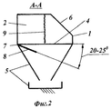
Сущность изобретения поясняется чертежом, где на фиг.1 показан прибор на виде сверху; на фиг.2 - прибор в разрезе по А-А на фиг.1. The invention is illustrated in the drawing, where figure 1 shows the device in a plan view; figure 2 - the device in section along aa in figure 1.
Прибор для исследования центробежных аппаратов разбрасывателей сыпучих материалов выполнен в виде полого кольца 1. Внутри кольца 1 закреплены тонкие вертикальные перегородки 2, задние части которых отклонены от радиального положения в сторону вращения диска 3. Перегородки 2 образуют с внутренней стороны кольца 1 ячейки 4, каждая из которых снабжена разгрузочным поддоном 5. Задняя стенка 6 прибора выполнена в виде расширяющегося книзу усеченного конуса. Над передней частью разгрузочного поддона 5 к его верхней кромке 7 консольно прикреплена пластина 8, которая отклонена вниз. В средней по глубине части каждой ячейки 4 по всему поперечному ее сечению установлен успокоитель 9, который прикреплен к верхней части ячейки 4 и выполнен в виде набора лент из прочного эластичного материала. The device for studying centrifugal apparatuses for spreaders of bulk materials is made in the form of a
Устройство работает следующим образом. The device operates as follows.
Прибор закрепляется на раме разбрасывателя соосно с диском 3. Исследования центробежного аппарата выполняются при неподвижном разбрасывателе, то есть в стационарных условиях. The device is mounted on the spreader frame coaxially with the disk 3. Studies of the centrifugal apparatus are carried out with the spreader stationary, that is, under stationary conditions.
Поданный на вращающийся диск 3 сыпучий материал под воздействием центробежных сил слетает в сторону ячеек 4 прибора. Он разделяется вертикальными перегородками 2 и практически полностью улавливается ячейками 4. Этому содействует то, что скорость частиц сыпучего материала гасится в результате их ударов по успокоителю 9, который установлен поперек к направлению полета частиц. Часть материала сразу оседает в разгрузочном поддоне 5. Другая его часть, потеряв скорость после встречи с успокоителем 9 и отразившись от задней стенки 6, а возможно и вновь от успокоителя 9, также попадает в поддон 5. Воздушные вихревые потоки, встретив сопротивление со стороны успокоителя 9 и отклоненной вниз пластины 8, гасятся и теряют способность к выносу частиц сыпучего материала из ячеек 4 прибора. Сыпучий материал на пластине 8 не скапливается, так как он сдувается в ячейку 4 прибора воздушным потоком. Кроме того, пластина 8 закреплена консольно, отклонена вниз и в результате ее автоколебаний, вызванных вибрацией рамы разбрасывателя и воздушными вихревыми потоками, она самоочищается. После прекращения подачи на диск 3 сыпучего материала диск 3 выключают из работы. Сыпучий материал собирают из поддонов 5 каждой ячейки 4 прибора и путем взвешивания определяют такие важнейшие технологические параметры работы центробежного аппарата, как угол разбрасывания и распределение сыпучего материала по углу разбрасывания. Результаты этих замеров используют в дальнейшем при совершенствовании конструкции центробежного аппарата разбрасывателя сыпучих материалов. The bulk material fed to the rotating disk 3 under the influence of centrifugal forces flies towards the cells 4 of the device. It is separated by
Задние части вертикальных перегородок 2 отклонены от радиального положения в сторону вращения диска 3 на угол 55-65o. В противном случае будет происходить отражение частиц сыпучего материала от перегородок 2. Задняя стенка 6 прибора может быть выполнена из плотной ткани и отклонена от вертикали на угол 40-50o. Значение этого угла менее 40o может привести к вылету из ячеек 4 прибора отраженных от стенки 6 частиц, а более 50o - к увеличению габаритов прибора. Пластина 8 выполнена из жесткого материала и перекрывает верхнюю часть разгрузочного поддона 5 на 0,25-0,33 глубины ячейки 4. Пластина 8 меньшей длины не будет способна эффективно гасить воздушные вихревые потоки, а при большей ее длине над пластиной 8 создаются дополнительно воздушные потоки, которыми выдуваются из ячеек 4 частицы сыпучего материала. Пластина 8 должна быть отклонена вниз от горизонтали на угол 20-25o. Меньший угол отклонения может вызвать заторы сыпучего материала на пластине 8, а больший - значительно снижает ее эффективность как гасителя воздушных вихревых потоков. Успокоитель 9 может быть выполнен в виде набора лент, установленных, по меньшей мере, в два ряда с перекрытием друг друга по ширине. Ленты успокоителя 9 должны быть такой длины, чтобы нижние их края были на уровне верхней части разгрузочного поддона 5. Ширина лент успокоителя 9 должна составлять 15-25 мм. Ленты меньшей ширины неэффективно гасят скорость частиц сыпучего материала и воздушные вихревые потоки, а большей - создают частицам сыпучего материала непреодолимое препятствие, отразившись от которого частицы покидают ячейки.The rear parts of the
Использование предлагаемого устройства позволяет снизить погрешности проводимых с помощью прибора измерений при исследовании распределения сыпучего материала по углу разбрасывания центробежного аппарата, а в результате повысить равномерность распределения сыпучего материала по поверхности почвы и увеличить ширину захвата разбрасывателя. Это способствует повышению урожайности сельскохозяйственных культур, увеличению производительности машин, экономии топлива и снижению затрат труда. Using the proposed device can reduce the errors carried out using the device measurements when studying the distribution of bulk material by the angle of spread of the centrifugal apparatus, and as a result to increase the uniformity of the distribution of bulk material on the surface of the soil and increase the width of the spreader. This helps to increase crop yields, increase machine productivity, save fuel and reduce labor costs.
Claims (1)
Priority Applications (1)
| Application Number | Priority Date | Filing Date | Title |
|---|---|---|---|
| RU2001111104/13A RU2201059C2 (en) | 2001-04-20 | 2001-04-20 | Instrument for investigating centrifuges of bulk material spreading units |
Applications Claiming Priority (1)
| Application Number | Priority Date | Filing Date | Title |
|---|---|---|---|
| RU2001111104/13A RU2201059C2 (en) | 2001-04-20 | 2001-04-20 | Instrument for investigating centrifuges of bulk material spreading units |
Publications (2)
| Publication Number | Publication Date |
|---|---|
| RU2001111104A RU2001111104A (en) | 2003-03-27 |
| RU2201059C2 true RU2201059C2 (en) | 2003-03-27 |
Family
ID=20248841
Family Applications (1)
| Application Number | Title | Priority Date | Filing Date |
|---|---|---|---|
| RU2001111104/13A RU2201059C2 (en) | 2001-04-20 | 2001-04-20 | Instrument for investigating centrifuges of bulk material spreading units |
Country Status (1)
| Country | Link |
|---|---|
| RU (1) | RU2201059C2 (en) |
Cited By (1)
| Publication number | Priority date | Publication date | Assignee | Title |
|---|---|---|---|---|
| RU241974U1 (en) * | 2025-12-11 | 2026-03-06 | Федеральное государственное бюджетное образовательное учреждение высшего образования "Национальный исследовательский Мордовский государственный университет им. Н.П. Огарёва" | A test bench for studying the uniformity of application of mineral fertilizers by centrifugal working bodies |
Citations (4)
| Publication number | Priority date | Publication date | Assignee | Title |
|---|---|---|---|---|
| GB2074832B (en) * | 1980-05-02 | 1984-05-02 | Teagle W T | Broadcaster |
| EP0379103A1 (en) * | 1989-01-20 | 1990-07-25 | Amazonen-Werke H. Dreyer GmbH & Co. KG | Fertilizer broadcaster |
| DE3641080C2 (en) * | 1986-12-02 | 1994-05-19 | Amazonen Werke Dreyer H | Centrifugal fertilizer spreader |
| RU2104629C1 (en) * | 1991-01-18 | 1998-02-20 | Амазонен-Верке Х.Драйер ГмбХ унд Ко. КГ | Method and apparatus for determining fertilizer thrower adjustment parameters for providing required throwing width and amounts of fertilizer to be thrown depending on kind of fertilizer, method for adjustment of fertilizer thrower dosing devices mounted above throwing units, and fertilizer thrower |
-
2001
- 2001-04-20 RU RU2001111104/13A patent/RU2201059C2/en not_active IP Right Cessation
Patent Citations (4)
| Publication number | Priority date | Publication date | Assignee | Title |
|---|---|---|---|---|
| GB2074832B (en) * | 1980-05-02 | 1984-05-02 | Teagle W T | Broadcaster |
| DE3641080C2 (en) * | 1986-12-02 | 1994-05-19 | Amazonen Werke Dreyer H | Centrifugal fertilizer spreader |
| EP0379103A1 (en) * | 1989-01-20 | 1990-07-25 | Amazonen-Werke H. Dreyer GmbH & Co. KG | Fertilizer broadcaster |
| RU2104629C1 (en) * | 1991-01-18 | 1998-02-20 | Амазонен-Верке Х.Драйер ГмбХ унд Ко. КГ | Method and apparatus for determining fertilizer thrower adjustment parameters for providing required throwing width and amounts of fertilizer to be thrown depending on kind of fertilizer, method for adjustment of fertilizer thrower dosing devices mounted above throwing units, and fertilizer thrower |
Non-Patent Citations (1)
| Title |
|---|
| Информационный листок Краснодарского ЦНТИ №223-81. КАРАБАНИЦКИЙ А.П., ЯКИМОВ Ю.И. Прибор для регулирования туконаправителей разбрасывателей минеральных удобрений КСА-3. - 20.04.1981. * |
Cited By (1)
| Publication number | Priority date | Publication date | Assignee | Title |
|---|---|---|---|---|
| RU241974U1 (en) * | 2025-12-11 | 2026-03-06 | Федеральное государственное бюджетное образовательное учреждение высшего образования "Национальный исследовательский Мордовский государственный университет им. Н.П. Огарёва" | A test bench for studying the uniformity of application of mineral fertilizers by centrifugal working bodies |
Similar Documents
| Publication | Publication Date | Title |
|---|---|---|
| JP2008504195A (en) | Apparatus and method for loading a divided solid into a chamber | |
| US20130108366A1 (en) | Spreading device, particularly for spreading chippings | |
| US4062496A (en) | Spreader for particulate material | |
| EP0241982B1 (en) | A device for spreading material and a method of collecting same | |
| US4646910A (en) | Generalized high speed belt to belt transfer chute | |
| RU2205529C1 (en) | Pneumatic seeding unit | |
| RU2210201C1 (en) | Seeding unit for drill | |
| CN216102788U (en) | Unmanned plane | |
| RU2492615C2 (en) | Pneumatic-mechanical planting unit with vibration-orienting feeder for planting seed onion oriented with its disc downwards | |
| GB2055533A (en) | Centrifugal fertiliser spreader | |
| JPS5949860B2 (en) | Cutting piece discharge device | |
| JP7009235B2 (en) | Combination scale | |
| SU1521337A1 (en) | Centrifugal device for disseminating fertilizers | |
| SU1697904A1 (en) | Air separator | |
| US4391359A (en) | Sample splitter | |
| CN218706634U (en) | Vibration blanking chute for solving material blockage | |
| CN117426189B (en) | A method and device for improving the uniformity of centrifugal disc spreading | |
| SU1667681A1 (en) | Particulate material spreading device | |
| JP2021181065A (en) | Food sorting equipment | |
| SU1323000A1 (en) | Fertilizer distributor | |
| RU2748068C1 (en) | Laboratory stand for the study of the physical and mechanical properties of various types of solid mineral fertilizers and working bodies of centrifugal spreaders | |
| JP2714679B2 (en) | Vibratory seeder | |
| CN109396027B (en) | Double-shaking seed fine separator | |
| US2849122A (en) | Pan filter construction | |
| JPH048738Y2 (en) |
Legal Events
| Date | Code | Title | Description |
|---|---|---|---|
| MM4A | The patent is invalid due to non-payment of fees |
Effective date: 20030421 |