RU2201082C2 - Charging mechanism for grain processing apparatus - Google Patents
Charging mechanism for grain processing apparatus Download PDFInfo
- Publication number
- RU2201082C2 RU2201082C2 RU2001101180/13A RU2001101180A RU2201082C2 RU 2201082 C2 RU2201082 C2 RU 2201082C2 RU 2001101180/13 A RU2001101180/13 A RU 2001101180/13A RU 2001101180 A RU2001101180 A RU 2001101180A RU 2201082 C2 RU2201082 C2 RU 2201082C2
- Authority
- RU
- Russia
- Prior art keywords
- grain
- ejector
- gate
- hopper
- hole
- Prior art date
Links
Images
Landscapes
- Adjustment And Processing Of Grains (AREA)
Abstract
Description
Изобретение относится к области пищевой промышленности и может быть использовано при разработке автоматических устройств, предназначенных для прямой переработки крахмалосодержащего зерна в готовый к употреблению в пищу продукт. The invention relates to the field of food industry and can be used in the development of automatic devices for direct processing of starch-containing grain into a ready-to-eat food product.
Известен механизм загрузки устройства для переработки зерна (заявка Великобритании 2165437, 1985), содержащий бункер и выбрасыватель с отверстием, связанный с приводом. Механизм работает следующим образом. После окончания выпечки очередного зернового ломтика ломтик оказывается в свободном пространстве между верхней нагревательной головкой (поз. 43) и нижней нагревательной головкой (поз. 34) устройства для переработки зерна. Выбрасыватель (поз. 52) находится в исходном положении. Причем имеющиеся в нем отверстия (поз. 51) находятся под бункером (поз. 54) и заполнены зерном. Затем приводом (поз. 55, 56) выбрасыватель перемещается в зону между нагревательными головками, сбрасывает оттуда готовый зерновой ломтик и перемещает находящееся в его отверстиях зерно на нижнюю головку. Затем нижняя головка отводится вниз (фиг.6 описания к патенту Великобритании), образуя совестно со стаканом (поз. 31) рабочий объем для выпечки нового ломтика. При этом отверстия выбрасывателя освобождаются от зерна. Далее выбрасыватель возвращается приводом в исходное положение, где отверстия выбрасывателя заполняются новым зерном из бункера. При кажущейся простоте конструкции механизма он имеет существенные недостатки, а именно усложняет конструкцию устройства для переработки зерна и снижает его производительность. A known loading mechanism of a device for processing grain (application UK 2165437, 1985), containing a hopper and ejector with a hole associated with the drive. The mechanism works as follows. After baking the next grain slice, the slice is in the free space between the upper heating head (pos. 43) and the lower heating head (pos. 34) of the grain processing device. The ejector (key 52) is in its original position. Moreover, the holes in it (key 51) are located under the hopper (key 54) and are filled with grain. Then, with a drive (pos. 55, 56), the ejector moves into the zone between the heating heads, discards the finished grain slice from there and moves the grain located in its openings to the lower head. Then the lower head is retracted downward (FIG. 6 of the description of the patent of Great Britain), forming, conscientiously with a glass (key 31), a working volume for baking a new slice. In this case, the ejector holes are freed from grain. Then the ejector returns to the initial position by the drive, where the ejector holes are filled with new grain from the hopper. Despite the apparent simplicity of the design of the mechanism, it has significant drawbacks, namely, it complicates the design of the device for processing grain and reduces its productivity.
Поскольку доставка зерна выбрасывателем на нижнюю головку осуществляется перемещением зерна по элементам конструкции устройства для переработки зерна, то в этой зоне элементы конструкции устройства должны представлять собой одну плоскость без выемок и желательно без стыков. Выполнение этих требований приводит к усложнению конструкции устройства и росту его габаритов и веса. Кроме того, поскольку перед отводом выбрасывателя в исходное положение необходимо отвести нижнюю головку вниз, на что необходимо время, снижается производительность устройства и усложняется его конструкция. Since the delivery of grain by the ejector to the lower head is carried out by moving the grain along the structural elements of the device for processing grain, in this zone the structural elements of the device should be one plane without recesses and preferably without joints. The fulfillment of these requirements leads to a complication of the design of the device and an increase in its dimensions and weight. In addition, since before lowering the ejector to the initial position, it is necessary to take the lower head down, which takes time, the performance of the device is reduced and its design is complicated.
Известен механизм загрузки устройства для переработки зерна (заявка ЕПВ 0006575, 1979, прототип), содержащий бункер, выбрасыватель с отверстием, оснащенный упором, подпружиненный относительно выбрасывателя шибер с отверстием, связанный с приводом. Механизм работает следующим образом. После окончания выпечки очередного зернового ломтика ломтик оказывается в свободном пространстве между верхней нагревательной головкой (поз. 1) и нижней нагревательной головкой (поз. 5) устройства для переработки зерна. Выбрасыватель (поз. 37) находится в исходном положении, причем имеющееся в нем отверстие (поз. 40) находится под бункером (поз. 42) и заполнено зерном. Шибер (поз. 38) размещен в направляющих, выполненных в выбрасывателе, подпружинен относительно выбрасывателя пружиной сжатия (поз. 49) и связан с приводом (поз. 55). При этом отверстие (поз. 41) в шибере не совпадает с отверстием в выбрасывателе. A known loading mechanism of a device for processing grain (application EPO 0006575, 1979, prototype), comprising a hopper, an ejector with a hole, equipped with a stop, spring-loaded relative to the ejector, a gate with a hole associated with the drive. The mechanism works as follows. After baking the next grain slice, the slice is in the free space between the upper heating head (pos. 1) and the lower heating head (pos. 5) of the grain processing device. The ejector (pos. 37) is in the initial position, and the hole in it (pos. 40) is located under the hopper (pos. 42) and is filled with grain. The gate (pos. 38) is placed in the guides made in the ejector, is spring loaded relative to the ejector with a compression spring (pos. 49) and connected to the drive (pos. 55). In this case, the hole (pos. 41) in the gate does not coincide with the hole in the ejector.
Механизм работает следующим образом. Включается привод и начинает перемещать шибер, который через пружину двигает выбрасыватель. В ходе этого движения выбрасыватель сбрасывает готовый зерновой ломтик, а в тот момент, когда отверстие выбрасывателя с находящимся в нем зерном оказывается над нижней головкой, выполненный на выбрасывателе упор (поз. 45) упирается в бункер, и движение выбрасывателя прекращается. В то же время перемещение шибера продолжается, происходит сжатие пружины, и по мере совмещения отверстий выбрасывателя и шибера зерно из отверстия выбрасывателя, через отверстие в шибере перегружается на нижнюю головку. В момент полного совмещения отверстий выбрасывателя и шибера привод выключается. Затем привод включается в обратном направлении, шибер начинает двигаться к исходному положению. Отверстие шибера сдвигается относительно отверстия выбрасывателя. В это время пружина продолжает удерживать выбрасыватель в конечном положении, с момента, когда свободный ход пружины выбран, шибер начинает перемещать к исходному положению выбрасыватель. При совмещении отверстия выбрасывателя с отверстием бункера зерно из бункера заполняет отверстие выбрасывателя. Привод при этом отключается. The mechanism works as follows. The drive turns on and begins to move the gate, which moves the ejector through the spring. During this movement, the ejector drops the finished grain slice, and at the moment when the ejector hole with the grain located in it is above the lower head, the stop made on the ejector (key 45) rests on the hopper, and the ejector movement stops. At the same time, the movement of the gate continues, the spring is compressed, and as the holes of the ejector and the gate are combined, the grain from the hole of the ejector passes through the hole in the gate to the lower head. When the holes of the ejector and the gate are completely combined, the drive turns off. Then the drive turns on in the opposite direction, the gate begins to move to its original position. The gate of the gate moves relative to the hole of the ejector. At this time, the spring continues to hold the ejector in the final position, from the moment when the free stroke of the spring is selected, the gate begins to move the ejector to its original position. When combining the ejector hole with the hopper hole, the grain from the hopper fills the ejector hole. The drive shuts down.
Этот механизм также имеет существенные недостатки, а именно значительное время срабатывания и пониженную надежность. Легко видеть, что после достижения выбрасывателем конечного положения, для выгрузки зерна на нижнюю головку, шибер необходимо продолжать сдвигать вперед до совмещения отверстий выбрасывателя и шибера. Аналогично, началу отвода выбрасывателя в исходное положение предшествует сдвиг шибера назад. Вследствие этого время срабатывания механизма загрузки завышено, что уменьшает в целом производительность устройства для переработки зерна. Кроме того, поскольку в процессе эксплуатации возможно заклинивание выбрасывателя относительно бункера (например, из-за загрязнения направляющих), то в этой ситуации, при заклинивании выбрасывателя в исходном положении, в результате движения шибера относительно выбрасывателя, произойдет совмещение отверстий выбрасывателя и шибера и, как следствие, сброс всего зерна из бункера в зону рабочих органов устройства для переработки зерна, что недопустимо. This mechanism also has significant drawbacks, namely, a significant response time and reduced reliability. It is easy to see that after the ejector reaches its final position, to unload the grain on the lower head, the gate must be continued to move forward until the holes of the ejector and the gate are aligned. Similarly, the beginning of the removal of the ejector to its original position is preceded by a shift of the gate back. As a result, the response time of the loading mechanism is overestimated, which reduces the overall performance of the device for processing grain. In addition, since during operation it is possible to jam the ejector relative to the hopper (for example, due to contamination of the guides), in this situation, when the ejector is jammed in its original position, as a result of the gate movement relative to the ejector, the holes of the ejector and the gate will be combined and, as consequence, the discharge of all grain from the hopper into the area of the working bodies of the device for processing grain, which is unacceptable.
Задачами создания изобретения является уменьшение времени срабатывания механизма загрузки и повышение его надежности. The objectives of the invention is to reduce the response time of the loading mechanism and increase its reliability.
Решение поставленных задач достигается тем, что механизм загрузки устройства для переработки зерна содержит бункер, выбрасыватель с отверстием, связанный с приводом и оснащенный упором, подпружиненный относительно выбрасывателя шибер с фиксатором и ограничитель начального и конечного положения шибера. The solution of the tasks is achieved by the fact that the loading mechanism of the device for processing grain contains a hopper, an ejector with an opening connected to the drive and equipped with a stop, a spring-loaded gate with a lock spring and a limiter of the initial and final position of the gate.
Суть изобретения поясняется чертежами, где изображены:
на фиг.1 - вид сбоку на механизм в исходном положении,
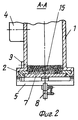
на фиг.2 - поперечный разрез механизма,
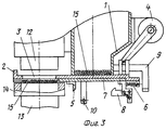
на фиг.3 - вид сбоку на механизм в конечном положении.The essence of the invention is illustrated by drawings, which depict:
figure 1 is a side view of the mechanism in its original position,
figure 2 is a transverse section of the mechanism,
figure 3 is a side view of the mechanism in the final position.
Механизм загрузки устройства для переработки зерна (фиг.1-3) содержит бункер 1, размещенный в направляющих бункера 1 выбрасыватель 2 с отверстием 3, связанный с приводом 4 и оснащенный упором 5, подпружиненный пружиной 6 относительно выбрасывателя 2 шибер 7 с фиксатором 8 и установленные на бункере 1 ограничители начального положения 9 и конечного положения 10 шибера 7. Рабочая зона механизма загрузки, где при его исходном положении находится готовый зерновой ломтик 11, размещается между верхней нагревательной головкой 12 и нижней нагревательной головкой 13 со стаканом 14 устройства для переработки зерна. Бункер 1 заполнен зерном 15. The loading mechanism of the device for processing grain (Figs. 1-3) contains a
Механизм устройства для переработки зерна функционирует следующим образом. В конце цикла изготовления зернового ломтика 11 он оказывается в зоне между верхней нагревательной головкой 12 и нижней нагревательной головкой 13 устройства для переработки зерна. Включается привод 4 и начинает перемещать относительно бункера 1 выбрасыватель 2 вместе с размещенным на направляющих выбрасывателя 2 шибером 7. Выбрасыватель 2 выбрасывает готовый зерновой ломтик 11 из зоны между нагревательными головками 12 и 13. При этом зерно 15, размещенное в отверстии 3 выбрасывателя 2, подается выбрасывателем 2 в зону между нагревательными головками 12 и 13. В результате взаимодействия фиксатора 8 с ограничителем конечного положения 10 шибера 7 фиксатор 8 выходит из зацепления с упором 5, пружина 6 смещает шибер 7 относительно выбрасывателя 2 на величину свободного хода шибера 7, в результате чего зерно 15 из отверстия 3 выбрасывателя 2 пересыпается на рабочую поверхность нижней головки 13. Одновременно происходит выключение привода 4. Затем привод 4 включается в обратном направлении и начинает перемещать выбрасыватель 2 вместе с шибером 7 к исходному положению. В процессе этого движения закрепленный на шибере 7 фиксатор 8 упирается в ограничитель начального положения 9 шибера 7, при продолжающемся движении выталкивателя 2 шибер 7 остается неподвижным и происходит натяжение пружины 6. При совмещении отверстия 3 выбрасывателя 2 с отверстием бункера 1 фиксатор 8 входит в зацепление с упором 5 выбрасывателя 2, а привод 4 отключается. На этом цикл работы механизма завершается. The mechanism of the device for processing grain operates as follows. At the end of the manufacturing cycle of the grain slice 11, it appears in the zone between the
Предлагаемая конструкция механизма загрузки для переработки зерна позволяет за меньшее время в сравнении с прототипом произвести выброс из рабочей зоны готового ломтика и произвести заправку в рабочую зону порции зерна для изготовления следующего ломтика. Это обеспечивается тем, что установка шибера в исходное положение относительно выбрасывателя происходит в процессе отвода выбрасывателя в исходное положение, в то же время в конструкции прототипа в начале шибер устанавливается в исходное положение, а затем в исходное положение отводится выбрасыватель. Снижение времени работы механизма загрузки уменьшает длительность цикла изготовления ломтика и, следовательно, увеличивает производительность устройства для переработки зерна. Кроме того, в сравнении с прототипом увеличивается надежность механизма. Например, в случае заклинивания выбрасывателя невозможен сброс зерна из бункера благодаря тому, что привод связан не с шибером, а с выбрасывателем. Таким образом, механизм загрузки предлагаемой конструкции обеспечивает выполнение поставленных целей и отличается существенной новизной. The proposed design of the loading mechanism for grain processing allows for less time in comparison with the prototype to eject the finished slice from the working area and refuel a portion of grain into the working area for the manufacture of the next slice. This is ensured by the fact that the installation of the gate in the initial position relative to the ejector occurs during the removal of the ejector to the initial position, at the same time, in the prototype design, the gate is installed in the initial position at the beginning, and then the ejector is returned to its initial position. Reducing the operating time of the loading mechanism reduces the length of the slice manufacturing cycle and, therefore, increases the productivity of the grain processing device. In addition, in comparison with the prototype increases the reliability of the mechanism. For example, in case of jamming of the ejector, it is impossible to discharge grain from the hopper due to the fact that the drive is connected not with the gate, but with the ejector. Thus, the loading mechanism of the proposed design ensures the achievement of goals and is notable for significant novelty.
Claims (1)
Priority Applications (1)
| Application Number | Priority Date | Filing Date | Title |
|---|---|---|---|
| RU2001101180/13A RU2201082C2 (en) | 2001-01-12 | 2001-01-12 | Charging mechanism for grain processing apparatus |
Applications Claiming Priority (1)
| Application Number | Priority Date | Filing Date | Title |
|---|---|---|---|
| RU2001101180/13A RU2201082C2 (en) | 2001-01-12 | 2001-01-12 | Charging mechanism for grain processing apparatus |
Publications (2)
| Publication Number | Publication Date |
|---|---|
| RU2001101180A RU2001101180A (en) | 2003-01-20 |
| RU2201082C2 true RU2201082C2 (en) | 2003-03-27 |
Family
ID=20244838
Family Applications (1)
| Application Number | Title | Priority Date | Filing Date |
|---|---|---|---|
| RU2001101180/13A RU2201082C2 (en) | 2001-01-12 | 2001-01-12 | Charging mechanism for grain processing apparatus |
Country Status (1)
| Country | Link |
|---|---|
| RU (1) | RU2201082C2 (en) |
Cited By (1)
| Publication number | Priority date | Publication date | Assignee | Title |
|---|---|---|---|---|
| CN104207318A (en) * | 2014-09-18 | 2014-12-17 | 天津明佳智能包装科技有限公司 | Automatic fastening system for bean vermicelli and preparation method of bean vermicelli |
Citations (5)
| Publication number | Priority date | Publication date | Assignee | Title |
|---|---|---|---|---|
| US4281593A (en) * | 1978-06-22 | 1981-08-04 | Omer Gevaert | Device for preparing food products from cooked and expanded cereals and products obtained |
| GB2165437A (en) * | 1984-10-16 | 1986-04-16 | Airin Kk | Production of cakes of granular material |
| RU2067833C1 (en) * | 1994-01-17 | 1996-10-20 | Михаил Михайлович Минаев | Grain processing apparatus |
| RU2080085C1 (en) * | 1994-12-30 | 1997-05-27 | Филиал Государственного научно-производственного предприятия "Прибор" | Device and method for producing cereal puffs |
| RU2157073C1 (en) * | 1999-02-04 | 2000-10-10 | Очин Вячеслав Федорович | Apparatus for producing briquettes from cereal raw material |
-
2001
- 2001-01-12 RU RU2001101180/13A patent/RU2201082C2/en not_active IP Right Cessation
Patent Citations (5)
| Publication number | Priority date | Publication date | Assignee | Title |
|---|---|---|---|---|
| US4281593A (en) * | 1978-06-22 | 1981-08-04 | Omer Gevaert | Device for preparing food products from cooked and expanded cereals and products obtained |
| GB2165437A (en) * | 1984-10-16 | 1986-04-16 | Airin Kk | Production of cakes of granular material |
| RU2067833C1 (en) * | 1994-01-17 | 1996-10-20 | Михаил Михайлович Минаев | Grain processing apparatus |
| RU2080085C1 (en) * | 1994-12-30 | 1997-05-27 | Филиал Государственного научно-производственного предприятия "Прибор" | Device and method for producing cereal puffs |
| RU2157073C1 (en) * | 1999-02-04 | 2000-10-10 | Очин Вячеслав Федорович | Apparatus for producing briquettes from cereal raw material |
Cited By (2)
| Publication number | Priority date | Publication date | Assignee | Title |
|---|---|---|---|---|
| CN104207318A (en) * | 2014-09-18 | 2014-12-17 | 天津明佳智能包装科技有限公司 | Automatic fastening system for bean vermicelli and preparation method of bean vermicelli |
| CN104207318B (en) * | 2014-09-18 | 2016-03-23 | 王勇 | A vermicelli automatic fastening system and its processing method |
Similar Documents
| Publication | Publication Date | Title |
|---|---|---|
| CH381594A (en) | Machine for filling and sealing containers | |
| WO2002063268A3 (en) | Bulk vessel feeder | |
| US4391186A (en) | Cotton press | |
| US2617560A (en) | Gun for discharging plastic composition | |
| US5018249A (en) | Device for the ejection of boxes through the exit of a container and a box adapted for use in such a device | |
| US5201266A (en) | Baler machine and method of baling | |
| US3355044A (en) | Refuse truck | |
| KR101735411B1 (en) | Noiseless and shock-free juice production line conveyor | |
| EP0709181B1 (en) | A rotatable bale release mechanism for a baler machine and method of baling | |
| US20030101564A1 (en) | Method and apparatus for recycling oil filters | |
| IE52410B1 (en) | Transfer conveying assembly | |
| DE2927564C2 (en) | ||
| KR102043557B1 (en) | Apparatus for preventing fallen ore of tripper car | |
| DE1511749A1 (en) | Method and device for packing objects | |
| KR20080020467A (en) | Card feeder | |
| JP3534278B2 (en) | Container discharge device | |
| US3942429A (en) | Method and apparatus for forming bales | |
| CN115285189A (en) | Stable form material transport equipment | |
| US1516770A (en) | Stacking mechanism | |
| US3190650A (en) | Ball door with positive closing mechanism | |
| DE1453131A1 (en) | Device for the automatic placement of cones | |
| US1602765A (en) | Vending machine | |
| DE3000575C2 (en) | Chain conveyor for coarse-grained material | |
| SU1164060A1 (en) | Apparatus for pressing loose materials | |
| JPH07120845A (en) | Opening / closing mechanism of document pressing device |
Legal Events
| Date | Code | Title | Description |
|---|---|---|---|
| MM4A | The patent is invalid due to non-payment of fees |
Effective date: 20030113 |