RU2201372C2 - Ship's hull - Google Patents
Ship's hull Download PDFInfo
- Publication number
- RU2201372C2 RU2201372C2 RU2000132538/28A RU2000132538A RU2201372C2 RU 2201372 C2 RU2201372 C2 RU 2201372C2 RU 2000132538/28 A RU2000132538/28 A RU 2000132538/28A RU 2000132538 A RU2000132538 A RU 2000132538A RU 2201372 C2 RU2201372 C2 RU 2201372C2
- Authority
- RU
- Russia
- Prior art keywords
- planes
- hull
- vessel
- plane
- stern
- Prior art date
Links
Images





Classifications
-
- Y—GENERAL TAGGING OF NEW TECHNOLOGICAL DEVELOPMENTS; GENERAL TAGGING OF CROSS-SECTIONAL TECHNOLOGIES SPANNING OVER SEVERAL SECTIONS OF THE IPC; TECHNICAL SUBJECTS COVERED BY FORMER USPC CROSS-REFERENCE ART COLLECTIONS [XRACs] AND DIGESTS
- Y02—TECHNOLOGIES OR APPLICATIONS FOR MITIGATION OR ADAPTATION AGAINST CLIMATE CHANGE
- Y02T—CLIMATE CHANGE MITIGATION TECHNOLOGIES RELATED TO TRANSPORTATION
- Y02T70/00—Maritime or waterways transport
- Y02T70/10—Measures concerning design or construction of watercraft hulls
Landscapes
- Other Liquid Machine Or Engine Such As Wave Power Use (AREA)
Abstract
Description
Изобретение касается устройств для уменьшения гидродинамического сопротивления воды при движении судна. В частности, изобретение можно использовать для вновь строящихся и эксплуатируемых судов, включая поплавки гидросамолетов и перископы подводных лодок. The invention relates to devices for reducing the hydrodynamic resistance of water when the vessel is moving. In particular, the invention can be used for newly built and operated ships, including seaplane floats and submarine periscopes.
Известны корпуса судов, снабженные различными приспособлениями для снижения сопротивления движению. Форма или геометрия корпусов судов, в особенности их подводной части, спроектированы с учетом различных факторов, например в патенте СССР [1], журнале "Наука и жизнь" [2], судну придают очертания, которые должны устранить всякое раздвигание воды в сторону носом движущегося судна и тем самым облегчить правильное образование гидродинамических струй под днищем судна. Known hulls equipped with various devices to reduce resistance to movement. The shape or geometry of the hulls of the vessels, especially their underwater parts, was designed taking into account various factors, for example, in the USSR patent [1], the journal “Science and Life” [2], the shape of the vessel is given to the vessel, which should eliminate any spreading of water in the direction of the nose moving vessel and thereby facilitate the correct formation of hydrodynamic jets under the bottom of the vessel.
Из авторского свидетельства СССР известно также судно [3], содержащее корпус, верхнюю палубу и надстройку с опорными элементами, а также амортизирующие элементы крепления надстройки, которое снабжено водонепроницаемым ограждением с планширем, установленным по периметру верхней палубы. A ship [3] is also known from the USSR author's certificate, which contains a hull, upper deck and a superstructure with supporting elements, as well as shock-absorbing fastening elements of the superstructure, which is equipped with a waterproof fence with a plank mounted around the perimeter of the upper deck.
Недостатками аналогов является достаточно большое сопротивление от раздвигания воды, в результате чего перед носом судна образуется наплыв (вспучивание) воды, которое создает большое дополнительное сопротивление. The disadvantages of the analogues is a sufficiently large resistance to the spreading of water, as a result of which an influx (swelling) of water forms in front of the bow of the vessel, which creates a large additional resistance.
В качестве прототипа выбрана обтекаемая поверхность твердого тела для газа или жидкости (корпус судна) [4], выполненная в виде последовательного ряда ступеней расширения-выравнивания потока, в котором для устранения явлений, связанных с отрывом потока и резкого снижения потерь на трение и расширение, основные размеры ступени потока выполнены следующими: угол раскрытия участка расширения 7o30'-15o, отношение большого диаметра к малому не более 1,25.As a prototype, the streamlined surface of the solid for gas or liquid (ship’s hull) [4], made in the form of a series of stages of expansion-alignment of the flow, in which to eliminate the phenomena associated with separation of the flow and a sharp reduction in friction and expansion losses, the main dimensions of the flow stage are as follows: the opening angle of the expansion section is 7 o 30'-15 o , the ratio of large to small diameters is not more than 1.25.
Недостатками прототипа является сложность устройства. Кроме того, он имеет достаточно большое сопротивление от раздвигания воды, в результате чего перед его фронтальной поверхностью образуется наплыв (вспучивание) воды, которое создает большое дополнительное сопротивление, а за кормой образуется водяная "впадина". The disadvantages of the prototype is the complexity of the device. In addition, it has a sufficiently large resistance from the spreading of water, as a result of which an influx (swelling) of water forms in front of its frontal surface, which creates a large additional resistance, and a water "cavity" forms behind the stern.
Задачей изобретения является устранение волнового и вихревого сопротивления жидкости и упрощение конструкции устройства. The objective of the invention is to eliminate the wave and eddy resistance of the liquid and simplify the design of the device.
Поставленная задача решается тем, что в известном судне, корпус которого выполнен в виде клиновидного или плоского профиля, согласно изобретению корпус снабжен устройством для уменьшения волнового и вихревого сопротивления, выполненным в виде плоскости, укрепленной вдоль корпуса судна на уровне ватерлинии, при этом у носа судна плоскости выполнены изогнутыми вверх, а за кормой смыкаются в одну плоскость. The problem is solved in that in a known vessel, the hull of which is made in the form of a wedge-shaped or flat profile, according to the invention, the hull is equipped with a device for reducing wave and vortex drag, made in the form of a plane fixed along the hull at the waterline, while at the bow of the vessel the planes are made curved upwards, and behind the stern they are closed in one plane.
Поставленная задача решается также и тем, что ширина плоскостей равна 0,1-0,3 высоты осадки судна. The problem is also solved by the fact that the width of the planes is equal to 0.1-0.3 of the height of the draft.
Поставленная задача решается также тем, что плоскости наклонены от горизонтали на угол, не превышающий 45o.The problem is also solved by the fact that the plane is inclined from the horizontal by an angle not exceeding 45 o .
Поставленная задача решается также тем, что плоскости выступают за корму на 1-5 м. The problem is also solved by the fact that the planes extend beyond the stern by 1-5 m.
Поставленная задача решается также тем, что кромки плоскостей выполнены из упругого материала, например из резины. The problem is also solved by the fact that the edges of the planes are made of an elastic material, such as rubber.
Поставленная задача решается также тем, что ширина упругих частей кромок оставляет 0,2-0,5 м. The problem is also solved by the fact that the width of the elastic parts of the edges leaves 0.2-0.5 m
Поставленная задача решается также тем, что плоскости прикреплены к корпусу шарнирно с возможностью изменения угла наклона плоскостей в процессе движения судна. The problem is also solved by the fact that the planes are attached to the hinge pivotally with the ability to change the angle of inclination of the planes during the movement of the vessel.
Поставленная задача решается также тем, что плоскости дополнительно снабжены устройством для регулирования их по высоте борта судна. The problem is also solved by the fact that the plane is additionally equipped with a device for regulating them along the height of the side of the vessel.
Общеизвестно, что гидродинамическое сопротивление тел, движущихся глубоко под водой, слагается из фрикционного сопротивления, т.е. сопротивления трения, вихревого и волнового сопротивления. Первое сопротивление зависит от качества поверхности и площади фрикционного контакта. Второе сопротивление - от вихрей, возникающих при отрыве потока от острых кромок и кормовой оконечности тела. И, наконец, волновое сопротивление возникает от давления стоячих или набегающих на корпус волн. При определенных условиях, когда скорость распространения волн в воде превышает скорость движения судна и источник возникновения волн находится сзади от вектора движения судна, волновое сопротивление может быть отрицательным, т.е. волны будут подталкивать судно. It is well known that the hydrodynamic resistance of bodies moving deep under water is composed of frictional resistance, i.e. friction, vortex and wave drag. The first resistance depends on the surface quality and the frictional contact area. The second resistance is from vortices arising when the flow is separated from sharp edges and the aft end of the body. And finally, the wave resistance arises from the pressure of the waves standing or incident on the body. Under certain conditions, when the speed of wave propagation in water exceeds the speed of the ship and the source of the wave is located behind the ship's motion vector, the wave resistance can be negative, i.e. waves will push the ship.
При движении судна давление перед носовой частью судна возрастает, а за кормой падает. Вначале, пока перепад давления невелик, вода из под носа успевает перетекать под корму, огибая корпус с боков и под днищем. По мере повышения скорости часть воды не успевает втянуться в это течение и начинает выпираться на поверхность в виде носового бугра, порождающего систему носовых волн. When the vessel moves, the pressure in front of the bow of the vessel increases, and falls behind the stern. At first, while the pressure drop is small, water from under the nose manages to flow under the stern, enveloping the hull from the sides and under the bottom. As the speed increases, part of the water does not have time to get involved in this flow and begins to bulge to the surface in the form of a nasal tubercle, generating a system of nasal waves.
По мере возрастания скорости тела возрастают все три вида сопротивления, при этом возрастание происходит неравномерно. У тихоходных - фрикционное сопротивление 80-90%, у быстроходных - его доля снижена до 40-60% в основном за счет нарастания волнового сопротивления. As the speed of the body increases, all three types of resistance increase, while the increase occurs unevenly. In slow-moving ones - frictional resistance is 80-90%, in high-speed ones - its share is reduced to 40-60% mainly due to an increase in wave resistance.
Явления, происходящие за кормой, носят обратный характер: начиная с некоторой скорости вода не успевает заполнять образующуюся здесь пустоту, в результате чего образуется впадина, генерирующая систему кормовых волн. The phenomena occurring behind the stern are of the opposite nature: starting from a certain speed, the water does not have time to fill the void formed here, as a result of which a hollow forms, generating a system of fodder waves.
Явление осложняется, когда до кормы доходят отражения носовых волн. The phenomenon is complicated when the reflection of the nasal waves reaches the stern.
Настоящее изобретение позволяет создать условия, при которых вода из под носа своевременно перетечет за корму, тем самым причина волнообразования устраняется или по крайней мере существенно уменьшается. The present invention allows to create conditions under which water from under the nose will flow over the feed in a timely manner, thereby eliminating the cause of wave formation or at least substantially decreasing.
Таким устройством может быть плоскость, расположенная вдоль борта судна и не позволяющая образоваться носовому бугру. Вместо этого, плоскость набегает на бугор, создавая условия глиссирования, одновременно повышая давление в этом бугре и обеспечивая условия перетекания воды под давлением вдоль корпуса к корме. Such a device may be a plane located along the side of the vessel and not allowing the formation of a bow tuber. Instead, the plane runs onto the hill, creating the conditions of gliding, while simultaneously increasing the pressure in this hill and providing conditions for the flow of water under pressure along the hull to the stern.
Для предупреждения появления волнового сопротивления при различной загрузке и осадке судна, количество плоскостей может быть более одного. To prevent the appearance of wave resistance with different loading and draft of the vessel, the number of planes can be more than one.
При наличии плоскостей вдоль бортов образуются два канала, ограниченных следующими поверхностями: боковая поверхность борта судна с одной стороны и поверхность неподвижной массы воды, не увлеченной в движении с другой стороны. Сверху канал ограничивается поверхностью плоскостей, а снизу - поверхностью неподвижной массы воды, не увлеченной в движении. If there are planes along the sides, two channels are formed, limited by the following surfaces: the side surface of the side of the vessel on one side and the surface of a fixed mass of water that is not carried away in movement on the other side. From above, the channel is limited by the surface of planes, and from below, by the surface of a motionless mass of water, not carried away in motion.
Образованные таким образом два канала позволяют воде проходить из-под носа судна за его корму. Two channels formed in this way allow water to pass from under the bow of the vessel beyond its stern.
Из-за того, что оба канала представляют собой сужающиеся виртуальные устройства, протекающая в них вода подчиняется закону неразрывности струи, скорость протекания воды по ним увеличивается. Due to the fact that both channels are narrowing virtual devices, the water flowing in them obeys the law of continuity of the jet, the speed of water flow through them increases.
Таким образом, образующийся перед носом судна носовой бугор воды будет перенесен за корму по образованному плоскостями каналу, заполняя образовавшуюся впадину, тем самым предупреждая волновое и вихревое сопротивление. Обе боковые плоскости за кормой сходятся и образуют кормовую плоскость, выступающую за корму на 1-5 м. Такая кормовая плоскость закрывает кормовую впадину от доступа в нее атмосферного воздуха и пониженное давление за кормой способствует увеличению скорости боковых потоков, а следовательно, понижению сопротивления движению судна. Thus, the nasal tuber of water formed in front of the bow of the vessel will be transferred behind the stern along the channel formed by the planes, filling the formed cavity, thereby preventing wave and vortex resistance. Both lateral planes behind the stern converge and form a stern plane, which extends 1-5 m behind the stern. Such a stern plane closes the aft cavity from the access of atmospheric air into it and the low pressure behind the stern increases the speed of side flows and, consequently, reduces the resistance to movement of the vessel .
Выполнение кормовой плоскости протяженностью менее 1 м не перекрывает всю впадину за кормой. Выполнение кормовой плоскости протяженностью более 5 м бессмысленно, поскольку как правило впадина не бывает большей длины. The implementation of the aft plane with a length of less than 1 m does not cover the entire cavity behind the stern. The implementation of the aft plane with a length of more than 5 m is pointless, since as a rule the depression does not happen to be longer.
По мере увеличения скорости судна сужение действующих каналов будет увеличиваться по следующей причине - увеличение скорости движения слоя воды на границе борт судна и неподвижный слой остальной массы воды. При увеличении скорости этого потока, по закону Паскаля, давление в этом потоке снижается, и поэтому внешним повышением давления спокойной жидкости будет все больше сужать канал движущейся воды с низким давлением. Происходит саморегуляция величины сечения каналов в зависимости от скорости судна. As the speed of the vessel increases, the narrowing of the existing channels will increase for the following reason - an increase in the speed of the water layer at the border of the side of the vessel and a fixed layer of the remaining mass of water. With an increase in the velocity of this flow, according to Pascal's law, the pressure in this flow decreases, and therefore, an external increase in the pressure of a still liquid will narrow the channel of moving water with low pressure more and more. Self-regulation of the value of the cross section of the channels depending on the speed of the vessel.
Плоскости могут быть установлены с наклоном до 45o относительно горизонтали. Такая установка плоскостей позволяет выполнить каналы трапецеидальной формы, ограничивая протяженность виртуального канала с неподвижной массой воды и естественно, не вовлекать в движение значительные массы прилегающей к судну воды. Установка плоскостей под отрицательным углом к горизонту нецелесообразна, поскольку в этом случае вода будет интенсивно вытесняться плоскостями в стороны и потеряется весь смысл плоскостей и образования канала. Выполнение угла к горизонту более 45o также нецелесообразна, поскольку в этом случае сечение канала становится слишком малым, и такой канал не позволяет пропустить всю воду с носового бугра в кормовую впадину.The planes can be set with a slope of up to 45 o relative to the horizontal. Such an installation of planes allows you to make channels of a trapezoidal shape, limiting the length of the virtual channel with a fixed mass of water and, naturally, not to involve significant masses of water adjacent to the vessel in the movement. Setting the planes at a negative angle to the horizon is impractical, since in this case the water will be intensively displaced by the planes to the sides and the whole meaning of the planes and the formation of the channel will be lost. The implementation of the angle to the horizon of more than 45 o is also impractical, since in this case the cross section of the channel becomes too small, and such a channel does not allow all water to pass from the bow to the aft cavity.
В носовой части судна плоскости установлены выше ватерлинии и плавно переходят в горизонтальные участки. In the bow of the vessel, the planes are installed above the waterline and smoothly transition into horizontal sections.
Ширину плоскостей выбирают равной 0,05-0,3 высоты осадки судна. Если выполнить ширину плоскостей меньшей 0,05 высоты осадки, то такие плоскости не дадут ощутимого эффекта, поскольку будут слишком узкими для перевода всей массы воды нового бугра. С увеличением скорости увеличивается носовой бугор и плоскости должны быть существенно шире - до 0,3 высоты осадки судна. Большую ширину плоскости принимать нецелесообразно, поскольку в этом случае ширина плоскости становится избыточной и возникают большие значения фрикционного трения. The width of the planes is chosen equal to 0.05-0.3 the height of the draft. If the width of the planes is less than 0.05 precipitation heights, then such planes will not give a tangible effect, since they will be too narrow to transfer the entire mass of water of the new hillock. With increasing speed, the bow tubercle increases and the planes should be much wider - up to 0.3 of the draft. It is impractical to take a large plane width, since in this case the plane width becomes excessive and large values of frictional friction arise.
Кромки плоскостей удобно выполнять из упругого материала, например резины, и известными методами крепить к плоскостям. При этом кромка может вибрировать в резонансе с колебаниями воды и существенно уменьшить фрикционное трение. Такие вибрации возникают при ширине кромок от 0,2 до 0,5 м. Более узкие кромки становятся достаточно жесткими и не выполняют своей роли, а более 0,5 м становятся наоборот слишком мягкими и не обеспечивают работу плоскостей по переносу воды из-под носа в кормовую часть. The edges of the planes are conveniently made of an elastic material, such as rubber, and are attached to the planes by known methods. In this case, the edge can vibrate in resonance with water vibrations and significantly reduce frictional friction. Such vibrations occur when the width of the edges is from 0.2 to 0.5 m. The narrower edges become quite rigid and do not fulfill their role, and more than 0.5 m, on the contrary, become too soft and do not provide the work of the planes to transfer water from under the nose in the stern.
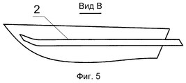
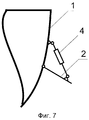
Изобретение поясняется чертежами, где на фиг.1 изображен вид судна в плане; на фиг.2 - разрез А-А фиг.1; на фиг.3 - то же, но с наклонной установкой плоскостей; на фиг.4 - вид судна сбоку (вид Б фиг.2); на фиг.5 - то же, но с установкой наклонных плоскостей (вид В фиг.3); на фиг.6 - то же, но установка нескольких плоскостей вдоль одного борта; на фиг.7 - установка плоскостей с возможностью их шарнирного крепления к корпусу судна и поворота; на фиг.8 - установка плоскостей с возможностью их вертикального перемещения; на фиг. 9 - установка плоскостей с упругой кромкой и возможностью шарнирной установки плоскостей. The invention is illustrated by drawings, where in Fig.1 shows a view of the vessel in plan; figure 2 is a section aa of figure 1; figure 3 is the same, but with an inclined installation of the planes; figure 4 is a side view of the vessel (view B of figure 2); figure 5 is the same, but with the installation of inclined planes (view In figure 3); figure 6 is the same, but the installation of several planes along one side; Fig.7 - the installation of the planes with the possibility of their articulation to the hull and rotation; on Fig - installation of planes with the possibility of vertical movement; in FIG. 9 - installation of planes with an elastic edge and the possibility of articulated installation of planes.
Корпус судна состоит из обшивки 1, к которой прикреплены плоскости 2. Плоскости проходят вдоль корпуса и за кормой судна смыкаются в кормовую плоскость 3, выходящую за корму на 1-5 м. Плоскости 2 могут быть прикреплены к обшивке посредством устройства шарнирного 4 вертикального перемещения 5 с пневматическим, гидравлическим или иным известным приводом. К плоскостям крепят упругие кромки 6 известными методами. The hull of the vessel consists of a
Судно перемещается следующим образом. При сходе судна на воду и его загрузке оно дает осадку до уровня ватерлинии. При этом плоскости 2 уходят немного ниже поверхности воды. Если есть возможность перемещения, то с помощью устройства вертикального перемещения 5 плоскости 2 устанавливают на необходимую глубину. При отсутствии механизма вертикального перемещения, но при установке двух и более плоскостей, каждая из плоскостей будет дополнительно погружаться, обеспечивая вступление в работу плоскостей по мере загрузки судна. Для судов с небольшой загрузкой достаточно одной плоскости 2 по каждому борту судна, при этом плоскости 2 могут быть закреплены на обшивке 1 неподвижно. The ship moves as follows. When the vessel descends to the water and is loaded, it gives draft to the level of the waterline. In this case, the
При увеличении скорости движения судна или изменении внешних условий, например осадки судна, можно с помощью устройства шарнирного перемещения 4 изменить угол плоскостей относительно вертикали и выбрать наиболее приемлемое положение плоскостей. When increasing the speed of the ship or changing external conditions, such as draft, you can use the device articulated
Выполнение корпуса судна согласно изобретению позволяет существенно снизить волновое и вихревое сопротивление движению судна в водной среде, повысить его экономичность. The implementation of the hull of the vessel according to the invention allows to significantly reduce the wave and vortex resistance to movement of the vessel in the aquatic environment, to increase its efficiency.
Источники информации
1. Патент СССР 2734, кл. В 63 В 3/00, 30.04.1927 г.Sources of information
1. USSR patent 2734, cl. B 63
2. Журнал "Наука и жизнь", 9, 1998 г., стр.25-26. 2. The journal "Science and Life", 9, 1998, pp. 25-26.
3. Авторское свидетельство СССР 1505835, кл. В 63 В 15/00, 07.09.89. 3. Copyright certificate of the USSR 1505835, cl. B 63 B 15/00, 09/07/89.
4. Авторское свидетельство СССР 466345, кл. F 04 D 29/52, 07.09.69. - (прототип). 4. Copyright certificate of the USSR 466345, cl. F 04 D 29/52, 09/07/69. - (prototype).
Claims (8)
Priority Applications (1)
| Application Number | Priority Date | Filing Date | Title |
|---|---|---|---|
| RU2000132538/28A RU2201372C2 (en) | 2000-12-26 | 2000-12-26 | Ship's hull |
Applications Claiming Priority (1)
| Application Number | Priority Date | Filing Date | Title |
|---|---|---|---|
| RU2000132538/28A RU2201372C2 (en) | 2000-12-26 | 2000-12-26 | Ship's hull |
Publications (2)
| Publication Number | Publication Date |
|---|---|
| RU2000132538A RU2000132538A (en) | 2002-12-27 |
| RU2201372C2 true RU2201372C2 (en) | 2003-03-27 |
Family
ID=20243961
Family Applications (1)
| Application Number | Title | Priority Date | Filing Date |
|---|---|---|---|
| RU2000132538/28A RU2201372C2 (en) | 2000-12-26 | 2000-12-26 | Ship's hull |
Country Status (1)
| Country | Link |
|---|---|
| RU (1) | RU2201372C2 (en) |
Cited By (2)
| Publication number | Priority date | Publication date | Assignee | Title |
|---|---|---|---|---|
| RU168863U1 (en) * | 2016-06-16 | 2017-02-21 | Федеральное государственное автономное образовательное учреждение высшего образования "Северный (Арктический) федеральный университет имени М.В. Ломоносова" (САФУ) | Non-self-propelled hull |
| RU225037U1 (en) * | 2023-09-06 | 2024-04-12 | Игорь Сергеевич Ковалёв | Fast ship hull |
Citations (4)
| Publication number | Priority date | Publication date | Assignee | Title |
|---|---|---|---|---|
| DE2814260A1 (en) * | 1978-04-03 | 1979-10-11 | Horst Dipl Ing Tuppeck | Wave profile modifying fins for ships - are horizontal surfaces projecting from hull, located so as to flatten bow and stern waves, and angle of incidence may be fixed or variable |
| GB1561124A (en) * | 1976-08-31 | 1980-02-13 | Hydroconic Ltd | Twin hull marine vessels |
| DE3236188A1 (en) * | 1982-06-23 | 1983-12-29 | Kawasaki Jukogyo K.K., Kobe, Hyogo | Device for reducing the wave resistance of a vessel |
| SU1255502A1 (en) * | 1984-11-02 | 1986-09-07 | Ленинградский Ордена Трудового Красного Знамени Институт Водного Транспорта | Ship bow |
-
2000
- 2000-12-26 RU RU2000132538/28A patent/RU2201372C2/en not_active IP Right Cessation
Patent Citations (4)
| Publication number | Priority date | Publication date | Assignee | Title |
|---|---|---|---|---|
| GB1561124A (en) * | 1976-08-31 | 1980-02-13 | Hydroconic Ltd | Twin hull marine vessels |
| DE2814260A1 (en) * | 1978-04-03 | 1979-10-11 | Horst Dipl Ing Tuppeck | Wave profile modifying fins for ships - are horizontal surfaces projecting from hull, located so as to flatten bow and stern waves, and angle of incidence may be fixed or variable |
| DE3236188A1 (en) * | 1982-06-23 | 1983-12-29 | Kawasaki Jukogyo K.K., Kobe, Hyogo | Device for reducing the wave resistance of a vessel |
| SU1255502A1 (en) * | 1984-11-02 | 1986-09-07 | Ленинградский Ордена Трудового Красного Знамени Институт Водного Транспорта | Ship bow |
Cited By (2)
| Publication number | Priority date | Publication date | Assignee | Title |
|---|---|---|---|---|
| RU168863U1 (en) * | 2016-06-16 | 2017-02-21 | Федеральное государственное автономное образовательное учреждение высшего образования "Северный (Арктический) федеральный университет имени М.В. Ломоносова" (САФУ) | Non-self-propelled hull |
| RU225037U1 (en) * | 2023-09-06 | 2024-04-12 | Игорь Сергеевич Ковалёв | Fast ship hull |
Similar Documents
| Publication | Publication Date | Title |
|---|---|---|
| US6105527A (en) | Boat activated wake enhancement method and system | |
| US5860766A (en) | Boat activated wave generator | |
| EP0335345B1 (en) | Improved hull construction for a swath vessel | |
| JP4607460B2 (en) | Air cushion ship | |
| KR101117038B1 (en) | Air cavity vessel with wedge-shaped cavities, longitudinally offset cavities, and roll control means and method for constructing the same | |
| US10518842B1 (en) | Boat hull | |
| RU2150401C1 (en) | Planing boat | |
| JP5986856B2 (en) | Commercial cargo ship | |
| US5402743A (en) | Deep chine hull design | |
| KR102461779B1 (en) | design of the front of the ship | |
| US5983823A (en) | High speed sport/utility boat | |
| JP3469197B2 (en) | Ship hull with single, three and two-hull structures | |
| US6148756A (en) | Method and mechanism for dynamic trim of a fast moving, planning or semi-planning ship hull | |
| RU97104001A (en) | HYDROPLANE | |
| EP2029420B1 (en) | Vessel provided with a foil below the waterline | |
| JP2022520136A (en) | Inflatable motorboat | |
| AU663476B2 (en) | Vee bottom structure for boat | |
| KR101800142B1 (en) | Ship hull structure comprising wave resistance increase minimizing steps | |
| RU2201372C2 (en) | Ship's hull | |
| WO2010033058A1 (en) | Hull form intended for vessels provided with an air cavity | |
| US5125352A (en) | Boat hull with bottom sloping upwardly and rearwardly between sponsons | |
| US7617793B2 (en) | Vessel provided with a foil situated below the waterline | |
| US5317982A (en) | Ship | |
| KR20050083655A (en) | Vessel provided with a foil situated below the waterline | |
| RU2302356C2 (en) | Hull of ship provided with central keel and side bilges |
Legal Events
| Date | Code | Title | Description |
|---|---|---|---|
| MM4A | The patent is invalid due to non-payment of fees |
Effective date: 20061227 |