RU2201475C2 - Device for production of high-purity aluminum - Google Patents
Device for production of high-purity aluminum Download PDFInfo
- Publication number
- RU2201475C2 RU2201475C2 RU2000127552A RU2000127552A RU2201475C2 RU 2201475 C2 RU2201475 C2 RU 2201475C2 RU 2000127552 A RU2000127552 A RU 2000127552A RU 2000127552 A RU2000127552 A RU 2000127552A RU 2201475 C2 RU2201475 C2 RU 2201475C2
- Authority
- RU
- Russia
- Prior art keywords
- bath
- electrolytic bath
- central cover
- covers
- cathodes
- Prior art date
Links
Images


Classifications
-
- C—CHEMISTRY; METALLURGY
- C25—ELECTROLYTIC OR ELECTROPHORETIC PROCESSES; APPARATUS THEREFOR
- C25C—PROCESSES FOR THE ELECTROLYTIC PRODUCTION, RECOVERY OR REFINING OF METALS; APPARATUS THEREFOR
- C25C3/00—Electrolytic production, recovery or refining of metals by electrolysis of melts
- C25C3/06—Electrolytic production, recovery or refining of metals by electrolysis of melts of aluminium
- C25C3/24—Refining
Landscapes
- Chemical & Material Sciences (AREA)
- Engineering & Computer Science (AREA)
- Chemical Kinetics & Catalysis (AREA)
- Electrochemistry (AREA)
- Materials Engineering (AREA)
- Metallurgy (AREA)
- Organic Chemistry (AREA)
- Electrolytic Production Of Metals (AREA)
- Manufacture And Refinement Of Metals (AREA)
Abstract
Description
Изобретение относится к устройству для получения сверхчистого алюминия способом трехслойного электролиза, состоящему из электролитической ванны, в которую сверху погружены электроды и которая закрыта сверху для уменьшения тепловых потерь. The invention relates to a device for producing ultrapure aluminum by a three-layer electrolysis method, consisting of an electrolytic bath in which electrodes are immersed from above and which is closed from above to reduce heat loss.
Электролизер для электролитического рафинирования состоит обычно из облицованной листовой сталью прямоугольной ванны, футерованной огнеупорным материалом. Во включенное в качестве анода углеродное дно заделаны токопроводящие шины из стали, а выше расположены три расплавленных слоя в следующем порядке:
- анодный металл (сплав очищаемого алюминия-сырца с содержанием около 40% меди);
- смесь криолита, а также фторида кальция, бария и алюминия в качестве среднего слоя;
- верхний слой, состоящий из рафинированного алюминия.An electrolytic cell for electrolytic refining usually consists of a rectangular bathtub lined with sheet steel lined with refractory material. Conducted busbars made of steel are embedded in the carbon bottom included as an anode, and three molten layers are located above in the following order:
- anode metal (an alloy of purified raw aluminum with a content of about 40% copper);
- a mixture of cryolite, as well as calcium fluoride, barium and aluminum as the middle layer;
- top layer consisting of refined aluminum.
В катодный металл погружены графитовые электроды, которые через расположенную над ванной катодную шину присоединены к токоподводу. Копильник служит для загрузки электролизера, причем при катодной плотности тока 0,3-0,5 А/см2 рабочие температуры составляют около 750oС.Graphite electrodes are immersed in the cathode metal, which are connected to the current lead through the cathode bus located above the bath. The piggy bank serves to load the electrolyzer, and at the cathodic current density of 0.3-0.5 A / cm 2 operating temperatures are about 750 o C.
С помощью известного электролизера можно в технических условиях рафинирования получить алюминий чистотой всего 99,99%. Поэтому предпринимались попытки поиска возможностей повышения степени чистоты. При этом было обнаружено, что загрязнения частично вызваны коррозией покрытия электролизера. В других случаях установлено, что графитированные электроды закрепляли на стальном стержне и для надежного контакта между графитом и сталью катодный зажим заливали железом. Также и здесь в расплав могли попасть продукты коррозии в качестве загрязнений. Другие вещества попадали в металл с пылью (кремний). Using a well-known electrolyzer, it is possible to obtain aluminum with a purity of only 99.99% under refining specifications. Therefore, attempts were made to search for opportunities to increase the degree of purity. It was found that the contamination was partially caused by corrosion of the electrolytic cell coating. In other cases, it was found that graphitized electrodes were fixed on a steel rod and, for reliable contact between graphite and steel, the cathode clamp was filled with iron. Also here, corrosion products as contaminants could get into the melt. Other substances fell into the metal with dust (silicon).
Для надлежащего электролитического рафинирования следует соблюдать определенные циклы очистки и контроля. В качестве примера здесь следует назвать следующие типичные меры. For proper electrolytic refining, certain cleaning and control cycles should be followed. The following typical measures should be mentioned here as an example.
1. Обмер и очистка угольных катодов
Катоды каждого электролизера следует ежедневно обмерять, с тем чтобы получить данные о состоянии контактных поверхностей угольного катода и очищенного алюминия. При этом определяют напряжение на каждом отдельном катоде.1. Measurement and cleaning of carbon cathodes
The cathodes of each cell should be measured daily in order to obtain data on the state of the contact surfaces of the carbon cathode and purified aluminum. In this case, the voltage at each individual cathode is determined.
Если значение напряжения лежит ниже минимального значения, например, 4,5 мВ, то угольные катоды вытягивают, т.е. с помощью пневматического тянущего устройства угольный катод вытягивают примерно на 600 мм над крышкой печи, а затем после отделения медной штанги от токоподводящей шины транспортируют к тележке для очистки катода. Для этих работ необходимо обеспечить непосредственный доступ персоналу. If the voltage value is below the minimum value, for example, 4.5 mV, then the carbon cathodes are pulled, i.e. using a pneumatic pulling device, the carbon cathode is pulled out about 600 mm above the furnace lid, and then after separating the copper rod from the current supply bus, it is transported to the cathode cleaning trolley. For this work, direct access to personnel is required.
2. Удаление пены из печей
В процессе электролиза на поверхности катода, здесь очищенный алюминий, образуется слой из преимущественно оксида алюминия и частиц электролита. Этот слой необходимо регулярно снимать, причем следует избегать движений ванны и перемешивания электролита.2. Removal of foam from furnaces
In the process of electrolysis on the surface of the cathode, here purified aluminum, a layer is formed of predominantly aluminum oxide and electrolyte particles. This layer must be removed regularly, and bath movements and electrolyte mixing should be avoided.
Часто слой пены склеивается на продольных сторонах печи с футеровкой. Тогда в этих местах слой пены следует отделить. Затем его подвигают в сторону, преимущественно к торцу печи. Often a layer of foam sticks to the longitudinal sides of the lined furnace. Then in these places the foam layer should be separated. Then it is moved to the side, mainly to the end of the furnace.
Снятие пены продолжается около 30 минут и производится каждую неделю, причем пену снимают последовательно со всех сторон печи. Для этого к поверхности печи должен иметься свободный доступ. The removal of foam lasts about 30 minutes and is performed every week, and the foam is removed sequentially from all sides of the furnace. For this, the surface of the furnace must be freely accessible.
3. Отбивка печей
В процессе электролиза на стенках печи образуются хорошо видимые отложения, преимущественно в зонах, где поверхность катода касается футеровки печи. Эти отложения обычно удаляют ломом, причем отбитый кусок отложений удаляют из печи черпаком для снятия пены или посредством горновых клещей.3. Oven beating
During electrolysis, well-visible deposits form on the walls of the furnace, mainly in areas where the cathode surface touches the furnace lining. These deposits are usually removed with a crowbar, whereby a broken off piece of deposits is removed from the furnace with a scoop to remove foam or by means of mite ticks.
Отбивку осуществляют примерно 2-4 раза в год, и она продолжается около 1 часа. При этом соответствующие поверхности печи должны иметь совершенно свободный доступ. Beating is carried out approximately 2-4 times a year, and it lasts about 1 hour. In this case, the corresponding surfaces of the furnace should have absolutely free access.
4. Установка новых угольных катодов
Установка и включение в работу новых угольных катодов происходит в три этапа, причем сначала угольный катод закрепляют на траверсе, так чтобы нижний конец находился примерно на 10 см над слоем металла. После 1 дня выдержки угольный катод погружают в ванну расплавленного металла, причем крышка печи остается закрытой для прохождения обслуживающего персонала.4. Installation of new carbon cathodes
The installation and commissioning of new carbon cathodes takes place in three stages, with the carbon cathode being first mounted on the beam so that the lower end is about 10 cm above the metal layer. After 1 day exposure, the carbon cathode is immersed in a bath of molten metal, and the lid of the furnace remains closed for passage of staff.
5. Заполнение слоя расплава
Для заполнения слоя расплава электролитом печь необходимо открыть. Тогда тигель с очищенным расплавом перемещают к печи, а слив тигеля соединяют со складным желобом.5. Filling the melt layer
To fill the melt layer with electrolyte, the furnace must be opened. Then the crucible with purified melt is moved to the furnace, and the crucible drain is connected to the folding trough.
При опрокидывании тигля во избежание удара струи электролита по поверхности металла между концом желоба и поверхностью ванны расплавленного металла держат черпак для снятия пены. Для заполнения крышку каждые 2-3 недели полностью снимают и сдвигают в продольном направлении примерно на 1 м, причем время заполнения составляет около 10 минут. При этом недопустимо движение ванны расплава. Уже поверхностное волновое движение в 1-2 см может привести к негативным последствиям в отношении чистоты катодного металла. When tipping the crucible in order to avoid impact of the electrolyte stream on the surface of the metal between the end of the trough and the surface of the bath of molten metal hold a scoop to remove foam. To fill the lid every 2-3 weeks completely remove and shift in the longitudinal direction by about 1 m, and the filling time is about 10 minutes. In this case, the movement of the molten bath is unacceptable. Already a surface wave motion of 1-2 cm can lead to negative consequences with respect to the purity of the cathode metal.
6. Измерение температуры
Поскольку регулирование температуры имеет решающее значение для процесса очистки в электролизере, измерение осуществляют каждый час ручными приборами. Печь открывают для этого примерно на 1 минуту. Температура должна поддерживаться постоянной до ±1oС.6. Temperature measurement
Since temperature control is crucial for the cleaning process in the cell, the measurement is carried out every hour with hand-held instruments. The furnace is opened for this for about 1 minute. The temperature should be kept constant up to ± 1 o C.
7. Измерение катодного слоя
Раз в неделю катодный слой измеряют во время отсоса печи. При этом в катод вертикально погружают стальной стержень и снова медленно извлекают. Процесс продолжается около 10 минут, пока на погруженном стержне не появится заметная маркировка.7. Measurement of the cathode layer
Once a week, the cathode layer is measured during the suction of the furnace. At the same time, a steel rod is vertically immersed in the cathode and slowly removed again. The process lasts about 10 minutes until a noticeable marking appears on the submerged rod.
8. Измерение высоты слоя расплава
Каждые две недели измеряют высоту слоя расплава у каждой печи. Время открывания печи составляет также около 10 минут.8. Measurement of the height of the melt layer
The height of the melt layer at each furnace is measured every two weeks. The opening time of the oven is also about 10 minutes.
При описанном выше обращении с устройством для получения сверхчистого алюминия возникает несколько, до сих пор неудовлетворительно решаемых проблем. With the above-described handling of a device for producing ultrapure aluminum, several, still unsatisfactorily solved problems arise.
Прежде всего следует назвать проблему герметизации при высоких температурах. Речь идет при этом о горизонтальных и вертикальных уплотнениях на плоских, скругленных и неподвижных, а также подвижных поверхностях. Из-за образования корки (см. п.3 "Отбивка печей") опоры для уплотнений со временем становятся неплоскими. Также при каждом техобслуживании и при обновлении футеровки край уплотнения смещается, так что удовлетворительная герметизация представляется возможной только при эластичном выполнении уплотнения. Это, однако, до сих пор не удавалось при высоких температурах из-за конструктивных проблем. First of all, the problem of sealing at high temperatures should be called. We are talking about horizontal and vertical seals on flat, rounded and stationary, as well as moving surfaces. Due to the formation of a crust (see
Кроме того, крышки должны быть выполнены гибкими для осуществления соответствующих манипуляций внутри печи. Они должны легко открываться и быстро закрываться, однако, с другой стороны, должны иметь также значительную жесткость, с тем чтобы они были, в частности, пригодны для обслуживания посередине круглых графитовых катодов. In addition, the lids must be flexible so that they can be handled internally. They should be easy to open and close quickly, however, on the other hand, they should also have considerable rigidity so that they are, in particular, suitable for maintenance in the middle of round graphite cathodes.
Далее материал изоляции должен иметь такой характер, чтобы можно было избежать даже мельчайших загрязнений жидкого металла. Further, the insulation material should be of such a nature that even the smallest contamination of the liquid metal could be avoided.
В акцептованной заявке ФРГ 1093997 описан токоподводящий элемент для подключения к катоду из жидкого алюминия при трехслойном способе. Согласно столбцу 4, строки 59 и далее на поверхности катодного слоя следует разместить экран, состоящий из алюминиевой плиты толщиной около 1 мм. Легкая алюминиевая плита образует в остальное время работы вместе с другими экранирующими деталями составное укрытие электролизера, однако она захватывается при каждом движении электрода, например, при замене электрода. The accepted application of Germany 1093997 describes a current-carrying element for connecting to a cathode of liquid aluminum in a three-layer method. According to
Недостатком этого известного укрытия, согласно прошедшей экспертизу заявке ФРГ 1093997, является отсутствие возможности хождения по укрытию, которое необходимо для проведения работ по техобслуживанию в разные интервалы времени. Кроме того, из-за недостатка изоляции укрытия и имеющихся между частями укрытия щелей возникают большие потери тепла, так что тепловой баланс известного устройства нарушен. The disadvantage of this well-known shelter, according to the examination of the application of Germany 1093997, which passed the examination, is the lack of the possibility of walking in the shelter, which is necessary for carrying out maintenance work at different time intervals. In addition, due to the lack of insulation of the shelter and the gaps between the parts of the shelter, large heat losses occur, so that the thermal balance of the known device is disturbed.
В патенте Великобритании 583831 описано устройство для электролитического рафинирования, у которого используется укрытие из керамического материала (п. 1 формулы изобретения "heat-insulating brickwork"). Однако используемые при этом керамические камни настолько утяжеляют укрытие, что его приходится изготовлять для стабильности из прочной стали (стр. 5, строка 5). Это затрудняет обслуживание электролизера в процессе электролиза. British Patent 5,838,331 describes an electrolytic refining device that uses a cover made of ceramic material (
Задачей настоящего изобретения является разработка устройства для получения сверхчистого алюминия чистотой 99,999% и выше, которое обеспечивало бы хороший выход продукта в единицу времени на единицу объема, например, при расходе энергии менее 20000 кВт/т полученного сверхчистого алюминия, и полную герметизацию электролизеров от потерь тепла и от попадания пыли, а также от выделений фторидов и пыли. The objective of the present invention is to develop a device for producing ultrapure aluminum with a purity of 99.999% and higher, which would ensure a good yield of the product per unit time per unit volume, for example, with an energy consumption of less than 20,000 kW / t of the obtained ultrapure aluminum, and complete sealing of electrolyzers from heat loss and dust, as well as fluoride and dust emissions.
Указанная задача решается за счет того, что в устройстве для получения сверхчистого алюминия из жидкого металла способом трехслойного электролиза, содержащем угольное дно электролитической ванны, включенное в качестве анода, графитовые катоды, погруженные в ванну сверху и включенные последовательно в продольном направлении, прямоугольное в плане укрытие для уменьшения потерь тепла, имеющее проходы для катодов, и копильник для добавки металла, установленный сбоку ванны, укрытие выполнено в виде трех крышек, расположенных параллельно друг другу в одной плоскости в продольном направлении электролитической ванны, причем центральная крышка выполнена с возможностью снятия вертикально вверх, а боковые крышки расположены с возможностью поворота посредством шарниров, и снабжено упругим керамическим материалом, размещенным по краю электролитической ванны и огибающим его и прижатым центральной крышкой для обеспечения теплоизоляции и герметизации от выхода газа, при этом графитовые катоды облицованы керамическими защитными колпаками, расположенными в проходах центральной крышки. This problem is solved due to the fact that in the device for producing ultrapure aluminum from liquid metal by the method of three-layer electrolysis containing the carbon bottom of the electrolytic bath, included as an anode, graphite cathodes immersed in the bath from above and connected sequentially in the longitudinal direction, a shelter rectangular in plan to reduce heat loss, with passages for the cathodes, and a piggy bank for adding metal, mounted on the side of the bath, the shelter is made in the form of three covers located parallel to one another in the same plane in the longitudinal direction of the electrolytic bath, the central cover being removable vertically upward, and the side covers are rotatable by hinges and provided with elastic ceramic material placed along the edge of the electrolytic bath and enveloping it and pressed by a central cover for providing thermal insulation and sealing against the gas outlet, while the graphite cathodes are lined with ceramic protective caps located in the passages centrally cover.
Согласно предпочтительным формам выполнения устройство отличается тем, что
- крышки выполнены в виде листов с выемками, в которые с геометрическим замыканием уложен керамический волокнистый материал, выступающий за периферию листов на 1-5 мм;
- центральная крышка имеет огибающую раму с отверстиями для прохода графитовых катодов, а ее узкие стороны прилегают к стойкам траверсы, расположенным на торцах электролитической ванны с возможностью регулирования их вертикального положения;
- отверстия к центральной крышке имеют задвижки, облицованные керамическим волокнистым материалом;
- каждая задвижка выполнена с полукруглым отверстием на обращенной к защитному колпаку стороне, радиус которого совпадает с внешним радиусом защитного колпака;
- центральная крышка соединена посредством подкосов с двумя несущими брусьями, прилегающими к стойкам траверсы и имеющими приводное устройство;
- несущие брусья выполнены подвижными с закрепленными на них крюкообразными шарнирами боковых крышек;
- боковые крышки имеют огибающую трубчатую раму, на которой закреплены листы с расположенными на них горизонтальными и вертикальными изолирующими плитами, причем горизонтальные изолирующие плиты закреплены на нижней стороне листов посредством керамических держателей, подвешенных на стальных штифтах, а вертикальные изолирующие плиты прилегают к краю электролитической ванны и упруго соединены между собой для восприятия давления;
- в боковых крышках выполнено, по меньшей мере, одно облицованное керамическим волокнистым материалом рабочее отверстие, закрываемое крышкой, имеющей выполненное из керамического волокнистого материала уплотнительное кольцо;
- на торцах боковых крышек расположены складные регулируемые по высоте ножки;
- изолирующие плиты выполнены из алюмосиликата, причем обращенные к наружной стороне электролитической ванны плиты имеют содержание Аl2О3, по меньшей мере, 44%, а обращенные внутрь электролитической ванны плиты имеют содержание Аl2О3, по меньшей мере, 73%.According to preferred embodiments, the device is characterized in that
- the covers are made in the form of sheets with recesses in which a ceramic fiber material is placed with a geometric closure, protruding 1-5 mm beyond the periphery of the sheets;
- the central cover has an envelope frame with holes for the passage of graphite cathodes, and its narrow sides are adjacent to the struts of the traverse located at the ends of the electrolytic bath with the possibility of regulating their vertical position;
- openings to the central cover have gate valves lined with ceramic fiber material;
- each valve is made with a semicircular hole on the side facing the protective cap, the radius of which coincides with the outer radius of the protective cap;
- the central cover is connected by struts to two load-bearing bars adjacent to the struts of the beam and having a drive device;
- the supporting bars are movable with hook-like hinges of the side covers fixed to them;
- the side covers have an envelope tubular frame on which sheets with horizontal and vertical insulating plates located on them are fixed, wherein the horizontal insulating plates are fixed to the underside of the sheets by means of ceramic holders suspended on steel pins, and the vertical insulating plates are adjacent to the edge of the electrolytic bath and Elastically interconnected to perceive pressure;
- at least one working hole lined with ceramic fiber material is closed in the side covers, which is closed by a cover having a sealing ring made of ceramic fiber material;
- at the ends of the side covers are folding height-adjustable legs;
- the insulating plates are made of aluminosilicate, with the plates facing the outside of the electrolytic bath having an Al 2 O 3 content of at least 44%, and the plates facing the inside of the electrolytic bath having an Al 2 O 3 content of at least 73%.
Устройство согласно изобретению для получения свехчистого алюминия из жидкого металла состоит из включенного в качестве анода угольного дна электролитической ванны, в которую сверху погружены последовательно включенные в продольном направлении графитовые электроды. Для уменьшения потерь тепла прямоугольное укрытие состоит из расположенных соответственно на продольных сторонах (по отношению к электролитической ванне) боковых частей 7, 8. В то время как центральное укрытие 1 прилегает на узких сторонах к стойкам 19, 20 траверсы, расположенным на торцах электролитической ванны 29, боковые части 7, 8 прилегают к несущим брусьям 31, 32, которые расположены в продольном направлении над центральным укрытием 1 и соединены со стойками 19,20 траверсы. Боковые части 7, 3 снабжены при этом крюкообразными шарнирами 2-4, прилегающими к многопозиционным подвескам 17, 18. Таким образом, боковые части 7,8 могут поворачиваться независимо от центрального укрытия 1. The device according to the invention for producing aluminum from liquid metal consists of a coal bottom included as an anode of the electrolytic bath, into which graphite electrodes are connected in series in the longitudinal direction from above. To reduce heat loss, a rectangular shelter consists of
Как в центральном укрытии 1, так и в боковых укрытиях, выполнены отверстия. Отверстия в центральном укрытии 1 выполнены с возможностью закрывания подвижными в поперечном направлении задвижками 11, 12. Задвижки состоят из жаропрочной листовой стали с керамической волокнистой облицовкой и имеют преимущественно на своей обращенной к защитному колпаку стороне полукруглую замыкающую кромку, радиус которой совпадает с внешним радиусом защитного колпака. Both in the
В боковых крышках 7, 8 также с возможностью закрывания крышкой 28 выполнено, по меньшей мере, одно рабочее отверстие 13. Особенностью является изоляция боковых частей 7, 8, состоящая из горизонтальных 23b и вертикальных 23а изолирующих плит. Горизонтальные изолирующие плиты 23b закреплены посредством керамических держателей 43, подвешенных на стальных штифтах 6, на нижней стороне боковых частей 7, 8, выполненных в виде листовой ванны 15, 16. Вертикальные изолирующие плиты 23а упруго соединены между собой и прилегают к краю электролитической ванны. At least one working hole 13 is made in the side covers 7, 8 with the possibility of closing the cover 28. A feature is the insulation of the
Другая особенность изолирующих плит 23а, 23b состоит в том, что они изготовлены из алюмосиликата, причем обращенные к наружной стороне печи плиты имеют содержание Аl2O3, по меньшей мере, 44%, а обращенные к внутреннему пространству плиты - содержание Al2O3, по меньшей мере, 73%.Another feature of the insulating
Для кратковременных инспекций и контрольных измерений в боковых частях 7,8 помимо рабочего отверстия 13 находится еще запорная плита 35, также герметизированная керамическим изоляционным материалом. Необходимое для уплотнительной функции прижимное усилие достигается у запорной плиты 35 за счет стреловидного в направлении силы тяжести выполнения запорной плоскости. Крышка 28 и рабочее отверстие 13 в боковых частях 7, 8 соответственно снабжены конически сходящимся керамическим уплотнительным кольцом для одновременного повышения прижимного усилия. For short-term inspections and control measurements in the lateral parts 7.8, in addition to the working hole 13, there is also a locking
Изобретение более подробно поясняется ниже с помощью примера выполнения. При этом
на фиг. 1 изображен фрагмент выполненного согласно изобретению укрытия, состоящего из отдельных крышек (вид сверху);
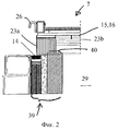
на фиг.2 - частичное сечение боковой крышки согласно изобретению в краевой зоне;
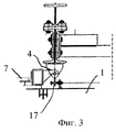
на фиг.3 - частичное сечение крышки в зоне подвижных несущих брусьев 31 с сочлененной с возможностью вращения боковой частью 7;
на фиг. 4a, b - виды сбоку (в качестве частичного сечения) устройства согласно изобретению для получения сверхчистого алюминия;
на фиг.5 - сечение боковой крышки согласно изобретению;
на фиг.6 - сечение центрального укрытия согласно изобретению;
на фиг.7a, b - виды сбоку запорной плиты;
на фиг.8 - вид сбоку электролитической ванны согласно изобретению.The invention is explained in more detail below using an example implementation. Wherein
in FIG. 1 shows a fragment of a shelter made according to the invention, consisting of individual covers (top view);
figure 2 is a partial section of a side cover according to the invention in the edge zone;
figure 3 is a partial section of the cover in the area of the movable load-
in FIG. 4a, b are side views (as a partial section) of a device according to the invention for producing ultrapure aluminum;
figure 5 is a cross section of a side cover according to the invention;
figure 6 is a cross section of the Central shelter according to the invention;
on figa, b - side views of the locking plate;
on Fig is a side view of the electrolytic bath according to the invention.
На фиг. 1 крышка, согласно изобретению, состоит из средней части 1, на которой слева и справа расположены подвижные посредством шарниров 2-6 боковые части 7, 8. In FIG. 1, the lid according to the invention consists of a
Средняя часть имеет соответствующее числу электродов число отверстий 9, 10, которые могут быть герметизированы каждое двумя задвижками 11, 12, снабженными полукруглыми выемками. The middle part has a number of holes 9, 10 corresponding to the number of electrodes, which can be sealed each with two valves 11, 12, equipped with semicircular recesses.
В одной боковой части крышки находится рабочее отверстие 13 для проведения измерений и инспекций во время трехслойного электролиза. Также это рабочее отверстие выполнено с возможностью закрывания отдельно расположенной крышкой. In one side of the lid is a working hole 13 for measurements and inspections during three-layer electrolysis. Also, this working hole is made with the possibility of closing a separately located lid.
Сечение на фиг.2 еще раз показывает устройство крышки в краевой зоне и расположение заполненной криолитом водяной чаши в качестве уплотнения 14 в зоне электролитической ванны. В щелях между частями 1, 7, 8 крышки могут быть расположены сплющиваемые уплотнения из расположенного в несколько слоев изолирующего коврика, так что каждая крышка изолирована как на поверхности прилегания, так и в боковой зоне. The cross section in figure 2 once again shows the lid device in the edge zone and the location of the cryolite-filled water bowl as a
Устройство изоляции в наружной части крышки приведено на фиг.2. На краю крышки видны вертикально стоящие изолирующие плиты 23а, которые воспринимают давление крышки на край ванны электролизера 29. В средней части 1 крышки горизонтальными слоями расположены изолирующие плиты 23b, поскольку здесь на переднем плане стоит изолирующее действие, а не воспринятие давления. The insulation device in the outer part of the cover is shown in Fig.2. On the edge of the lid, vertically standing insulating
Преимущества выполненной согласно изобретению крышки состоят в высокой теплоизоляции за счет полной герметизации, в применении инертных материалов, которые имеют уменьшенную газопроницаемость, а также в повышении выхода продукта на единицу объема в единицу времени за счет гибкого доступа внутрь печи во время электролиза. The advantages of the lid made according to the invention are high thermal insulation due to complete sealing, the use of inert materials that have a reduced gas permeability, as well as an increase in the product yield per unit volume per unit time due to flexible access to the inside of the furnace during electrolysis.
Крышки представляют собой, в основном, конструкцию из усиленных коробчатых листов 15, 16, которые в зоне отгиба из верхней стороны в боковины имеют выемки 5 для размещения боковой герметизации крышки в виде керамического волокнистого уплотнения 27 (фиг.6). За счет многопозиционной подвески 17, 18 и опирания средней части 1 на подкосы 30 она может быть выполнена при малой собственной массе очень жесткой, так что на торцах печи достаточно лишь небольших приводных усилий, чтобы поднять или опустить крышку. Кроме того, боковые крышки выполнены с возможностью хождения по ним во время электролиза. Также при кратковременных температурных ударах они не имеют деформаций, трещин и изломов. Они представляют собой, таким образом, оптимизацию различных требований к теплоизоляции, выходу продукта на единицу объема в единицу времени и защите окружающей среды. The covers are mainly a structure of reinforced box-shaped
Согласно предпочтительной форме выполнения, средняя часть прилегает к стойкам 19, 20 траверсы, изображенным на фиг.4а, 4b. Каждая стойка траверсы находится на торце печи. На ней расположены установочные устройства (катодные брусья) 21 для подъема и опускания электродов. According to a preferred embodiment, the middle part is adjacent to the
Далее из фиг.5 видны крюкообразно выполненные шарниры, с помощью которых боковые части крышки установлены с возможностью вращения вокруг центральной части или - после расцепления - также полного подъема от поверхности ванны. Next, from FIG. 5, hinges made of hinges are visible, by means of which the side parts of the lid are mounted to rotate around the central part or, after disengagement, also to rise completely from the surface of the bath.
На фиг.5 боковые части снабжены огибающей трубчатой рамой 22, на которой размещена листовая облицовка 16 для приема изолирующих плит. Для того чтобы боковые части после открывания можно было удерживать на определенном расстоянии от верхней кромки ванны, по меньшей мере, на торцах боковых частей находятся откидные ножки 24, 25. Они выполнены с возможностью регулирования по высоте, так что можно устанавливать различный угол открывания боковых крышек. In Fig. 5, the side parts are provided with an
Для открывания боковых частей на фиг.5 и 6 на средней части 1 укрытия предусмотрены крюкообразные удлинения в виде захвата 26. За счет большого угла открывания захвата 26 боковые крышки 7, 8 могут быть легко извлечены из зоны поворота. В случае использования для этой цели крана этот процесс можно ограничить подъемом и опусканием, поскольку ножки 24, 25 обеспечивают фиксацию в открытом положении. To open the side portions in FIGS. 5 and 6, hook extensions in the form of a
На фиг. 7а, 7b изображены виды сбоку запорной плиты 35. Они показывают помимо запорной плиты 35 ручку 36 для нее и держатель 37, например листовую деталь, которая прочно соединена с запорной плитой из силиката кальция болтами, зажимным устройством и т.п. Силикат кальция очень температуростоек и имеет высокое сопротивление разрушению, так что его можно подвергать высокой механической нагрузке. In FIG. 7a, 7b are side views of the locking
На фиг. 8 изображен вид сбоку электролитической ванны 29 согласно изобретению. Из нее видно также расположение запорной плиты 35. Она закрывает перелив 38, а именно таким образом, что выделения не могут улетучиваться даже при открывании запорной плиты 35. In FIG. 8 is a side view of an
Электролитическая ванна 29 имеет кладку (край 40 печи), которая на фиг.8 проходит горизонтально до запорной плиты 35, а затем V-образно. К кладке (край 40 печи) прилегает V-образный камень из силиката кальция, причем поверхности 35а, 35b прилегания закрывают горизонтальное укрытие, а V-образная вершина - зону открывания. The
Сбоку в наружной зоне электролитической ванны 29 находится лестница 34, по которой можно подняться на укрытие электролитической ванны 29. Для этого на боковых частях 7, 8 расположена решетка 41, прилегающая в зоне трубчатой рамы 22 (фиг.5). On the side in the outer zone of the
Обслуживающий персонал может отсюда открыть как крышку 28 на рабочем отверстии 13 (фиг.1), так и задвижки 11, 12 для контроля электродов 42 (фиг. 4а). From here, service personnel can open both the cover 28 on the working hole 13 (Fig. 1) and the gate valves 11, 12 for monitoring the electrodes 42 (Fig. 4a).
Благодаря конструкции и огнеупорной облицовке укрытия из трех частей достигаются следующие особенности. Thanks to the design and refractory lining of the shelter of three parts, the following features are achieved.
1. Герметизация ванны/электролизеров от потерь тепла. 1. Sealing baths / electrolyzers from heat loss.
2. Герметизация ванны/электролизеров от попадания пыли. 2. Sealing baths / electrolyzers from dust.
3. Уменьшение выделений фторидов и пыли примерно на 50%. 3. Reduced fluoride and dust emissions by about 50%.
4. Боковые крышки образуют рабочую платформу для обслуживающего персонала при очистке и замене угольных катодов. 4. Side covers form a working platform for maintenance personnel when cleaning and replacing carbon cathodes.
5. Сплошная конструкция без центральных подкосов обеспечивает хороший доступ при работах на поверхности ванны и короткое время открывания. 5. The continuous design without central struts provides good access when working on the surface of the bath and a short opening time.
6. Опора боковых крышек 7,8 с возможностью вращения посредством крюкообразных профилей/шарниров. 6. Support for side covers 7.8 rotatably by means of hook-shaped profiles / hinges.
7. За счет инертной огнеупорной облицовки внутренней стороны крышек в ванну не могут попасть металлические загрязнения в качестве продуктов реакции материала - основы крышек. 7. Due to the inert refractory lining of the inner side of the covers, metallic contaminants cannot enter the bath as reaction products of the material - the base of the covers.
8. Комбинируемая конструкция огнеупорной облицовки. 8. The combined design of the refractory lining.
9. Предотвращение продолжительных процессов открывания при отсосе электролизеров за счет рабочих отверстий в боковой крышке с запорной крышкой 28. 9. Prevention of lengthy opening processes during suction of electrolyzers due to working holes in the side cover with a locking cover 28.
10. Полная подвижность боковых крышек (снятие возможно, особенно во время процессов включения и выключения и добавки электролита). 10. Full mobility of the side covers (removal is possible, especially during on and off processes and electrolyte additions).
11. Применение жаропрочной стали в нагреваемых местах. 11. The use of heat-resistant steel in heated places.
12. Точное регулирование температуры печи (±1oС) за счет крышек угольных катодов или задвижек 11, 12 и V-образной запорной плиты 35 на переливе 38 (образование минимальных отверстий).12. Precise control of the furnace temperature (± 1 o C) due to the covers of the carbon cathodes or valves 11, 12 and the V-shaped
Точное регулирование температуры печи на ±1oС обеспечивается за счет открывания запорной плиты 35 на переливе 38. Запорная плита 35 состоит для этого из держателя 37, на котором закреплена ручка 36. Материал запорной плиты 35 состоит из силиката кальция и является, таким образом, высокожаростойким и в то же время достаточно прочным, чтобы выдерживать без повреждения механическую нагрузку при открывании и закрывании перелива 38.Accurate control of the furnace temperature by ± 1 o C is ensured by opening the locking
Предпочтительным образом запорная плита 35 закреплена сбоку на электролизере 29. За счет этого можно в значительной степени предотвратить выход печных газов, так что выброс при обслуживании печи согласно изобретению поддерживается на очень низком уровне. Особенно предпочтительным является боковое размещение запорной плиты 35 на торце печи, поскольку здесь восходящий поток тепла препятствует выходу газообразных загрязнений. В качестве дополнительной меры запорная плита 35 V-образно заострена в направлении перелива 38, благодаря чему образуется относительно длинное щелевое отверстие, посредством которого может происходить точное регулирование температуры при одновременно минимальной степени выбросов. Advantageously, the locking
Особенно предпочтительным образом камень из силиката кальция запорной плиты 35 выполнен Т-образным, причем вершина Т своими поверхностями 35а, 35b прилегает к футеровке 39 края 40 печи (кладка). Это обеспечивает надежное запирание электролизера 29 посредством запорной плиты 35. In a particularly preferred manner, the calcium silicate stone of the
Сбоку на краю 40 печи (кладка) закреплена лестница 34, которая позволяет обслуживающему персоналу подниматься на укрытие печи. Предпочтительным является закрепление лестницы 34 вблизи рабочего отверстия 13, так что все действия могут быть произведены коротким путем. Для улучшения возможности хождения на верхней стороне боковых частей 7, 8 в зоне трубчатой рамы 22 закреплена решетка 41. Боковые крышки являются, таким образом, рабочей платформой для очистки и замены угольных электродов или катодов. On the side at the
Claims (11)
Applications Claiming Priority (2)
| Application Number | Priority Date | Filing Date | Title |
|---|---|---|---|
| DE29919223.7 | 1999-11-02 | ||
| DE29919223U DE29919223U1 (en) | 1999-11-02 | 1999-11-02 | Device for extracting pure aluminum |
Publications (2)
| Publication Number | Publication Date |
|---|---|
| RU2000127552A RU2000127552A (en) | 2002-10-27 |
| RU2201475C2 true RU2201475C2 (en) | 2003-03-27 |
Family
ID=8081057
Family Applications (1)
| Application Number | Title | Priority Date | Filing Date |
|---|---|---|---|
| RU2000127552A RU2201475C2 (en) | 1999-11-02 | 2000-11-01 | Device for production of high-purity aluminum |
Country Status (6)
| Country | Link |
|---|---|
| JP (1) | JP3504230B2 (en) |
| DE (1) | DE29919223U1 (en) |
| FR (1) | FR2800394B1 (en) |
| NO (1) | NO328837B1 (en) |
| PL (1) | PL193668B1 (en) |
| RU (1) | RU2201475C2 (en) |
Cited By (4)
| Publication number | Priority date | Publication date | Assignee | Title |
|---|---|---|---|---|
| CN1332069C (en) * | 2003-12-06 | 2007-08-15 | 包头铝业股份有限公司 | Method for producing refined aluminum by cryolite-alumina fused salt electrolysis process |
| RU2406788C1 (en) * | 2009-12-02 | 2010-12-20 | Федеральное государственное образовательное учреждение высшего профессионального образования "Сибирский федеральный университет" | Method of removing coal froth from surface of electrolyte of aluminium electrolysis cell |
| RU2667144C2 (en) * | 2016-08-15 | 2018-09-17 | Гуйян Алюминум Магнизиум Дизайн Энд Рисерч Инститьют Ко., Лтд | New method and device for anode coating in aluminum electrolyser |
| RU2768897C2 (en) * | 2017-09-18 | 2022-03-25 | Бостон Электрометаллурджикал Корпорейшн | Systems and methods for electrolysis of molten oxides |
Families Citing this family (2)
| Publication number | Priority date | Publication date | Assignee | Title |
|---|---|---|---|---|
| JP2007247057A (en) * | 2006-02-16 | 2007-09-27 | Sumitomo Chemical Co Ltd | Cathode graphite material for aluminum three-layer electrolytic purification |
| CN112831803B (en) * | 2021-01-05 | 2021-11-16 | 中南大学 | A double-layer closed aluminum electrolytic cell and its upper thermal insulation cover |
Citations (3)
| Publication number | Priority date | Publication date | Assignee | Title |
|---|---|---|---|---|
| GB583831A (en) * | 1944-11-25 | 1946-12-31 | Aerlec Aluminium Ltd | New or improved apparatus for the refining or recovery of aluminium |
| DE2951720A1 (en) * | 1978-12-26 | 1980-07-03 | Aluminum Co Of America | METHOD FOR PRODUCING EXTREMELY PURE ALUMINUM |
| DE4329732C1 (en) * | 1993-09-03 | 1994-08-04 | Vaw Ver Aluminium Werke Ag | Aluminium@ refining |
Family Cites Families (2)
| Publication number | Priority date | Publication date | Assignee | Title |
|---|---|---|---|---|
| US2953506A (en) * | 1958-04-29 | 1960-09-20 | Aluminium Ind Ag | Method and apparatus for refining aluminum |
| DE3838828A1 (en) * | 1988-11-17 | 1990-05-23 | Vaw Ver Aluminium Werke Ag | Carbon electrode with a gas-tight, thermally-stable protective bell |
-
1999
- 1999-11-02 DE DE29919223U patent/DE29919223U1/en not_active Expired - Lifetime
-
2000
- 2000-10-16 NO NO20005189A patent/NO328837B1/en not_active IP Right Cessation
- 2000-10-20 PL PL343334A patent/PL193668B1/en unknown
- 2000-10-31 JP JP2000331766A patent/JP3504230B2/en not_active Expired - Lifetime
- 2000-11-01 RU RU2000127552A patent/RU2201475C2/en active
- 2000-11-02 FR FR0014051A patent/FR2800394B1/en not_active Expired - Lifetime
Patent Citations (3)
| Publication number | Priority date | Publication date | Assignee | Title |
|---|---|---|---|---|
| GB583831A (en) * | 1944-11-25 | 1946-12-31 | Aerlec Aluminium Ltd | New or improved apparatus for the refining or recovery of aluminium |
| DE2951720A1 (en) * | 1978-12-26 | 1980-07-03 | Aluminum Co Of America | METHOD FOR PRODUCING EXTREMELY PURE ALUMINUM |
| DE4329732C1 (en) * | 1993-09-03 | 1994-08-04 | Vaw Ver Aluminium Werke Ag | Aluminium@ refining |
Cited By (5)
| Publication number | Priority date | Publication date | Assignee | Title |
|---|---|---|---|---|
| CN1332069C (en) * | 2003-12-06 | 2007-08-15 | 包头铝业股份有限公司 | Method for producing refined aluminum by cryolite-alumina fused salt electrolysis process |
| RU2406788C1 (en) * | 2009-12-02 | 2010-12-20 | Федеральное государственное образовательное учреждение высшего профессионального образования "Сибирский федеральный университет" | Method of removing coal froth from surface of electrolyte of aluminium electrolysis cell |
| RU2667144C2 (en) * | 2016-08-15 | 2018-09-17 | Гуйян Алюминум Магнизиум Дизайн Энд Рисерч Инститьют Ко., Лтд | New method and device for anode coating in aluminum electrolyser |
| RU2768897C2 (en) * | 2017-09-18 | 2022-03-25 | Бостон Электрометаллурджикал Корпорейшн | Systems and methods for electrolysis of molten oxides |
| US11591703B2 (en) | 2017-09-18 | 2023-02-28 | Boston Electrometallurgical Corporation | Systems and methods for molten oxide electrolysis |
Also Published As
| Publication number | Publication date |
|---|---|
| FR2800394A1 (en) | 2001-05-04 |
| DE29919223U1 (en) | 2000-02-24 |
| NO20005189D0 (en) | 2000-10-16 |
| JP3504230B2 (en) | 2004-03-08 |
| JP2001172786A (en) | 2001-06-26 |
| PL343334A1 (en) | 2001-05-07 |
| PL193668B1 (en) | 2007-03-30 |
| FR2800394B1 (en) | 2003-03-28 |
| NO20005189L (en) | 2001-05-03 |
| NO328837B1 (en) | 2010-05-25 |
Similar Documents
| Publication | Publication Date | Title |
|---|---|---|
| CN101709485B (en) | Aluminum electrolytic cell for producing virgin aluminum by inert anode | |
| RU2041975C1 (en) | Electrolyzer for obtaining of aluminium and method for producing aluminium by means of electrolyzer | |
| CA1164823A (en) | Electrode arrangement in a cell for manufacture of aluminum from molten salts | |
| NZ197038A (en) | Cathode for the production of aluminium | |
| NZ202697A (en) | Floating cathode element for electrolytic production of aluminium | |
| RU2201475C2 (en) | Device for production of high-purity aluminum | |
| ES2291674T3 (en) | DESIGN OF CELL OF ELECTROLYTIC MANUFACTURE OF ALUMINUM, WITH SECTIONS OF MOBILE COVER OF INSULATION. | |
| CA1224746A (en) | Cell for the refining of aluminum | |
| US20060037863A1 (en) | Measuring duct offgas temperatures to improve electrolytic cell energy efficiency | |
| NO332628B1 (en) | Aluminum electro recovery cells with oxygen-generating anodes | |
| US3178363A (en) | Apparatus and process for production of aluminum and other metals by fused bath electrolysis | |
| US4406767A (en) | Anode hooding system for a fused salt electrolytic cell | |
| RU2582421C1 (en) | Cover of electrolyser for aluminium production | |
| AU2002236144B2 (en) | Thermally insulating structural components resistant to high temperature corrosive media | |
| NO180206B (en) | Structural parts for aluminum electrolysis cells | |
| RU2157429C2 (en) | Anode unit of aluminum electrolyzer with self-baking anode | |
| US20050040047A1 (en) | Use of infrared imaging to reduce energy consumption and fluoride comsumption | |
| RU2000127552A (en) | DEVICE FOR PRODUCING SUPERFINE ALUMINUM | |
| RU2550683C1 (en) | Electrolysis unit for aluminium making | |
| WO2017158501A1 (en) | Device for holding anode assemblies during electrical preheating of hall-héroult cells, and process for preheating hall-héroult cells using such device | |
| US4196067A (en) | Absorption of magnetic field lines in electrolytic reduction cells | |
| RU2509830C1 (en) | Electrolytic cell for production of aluminium | |
| CA3001293C (en) | Method and means for application of anode covering material (acm) in an electrolysis cell of hall-heroult type for aluminium production. | |
| AU2002236144A1 (en) | Thermally insulating structural components resistant to high temperature corrosive media | |
| CN215593210U (en) | Carbon-free aluminum electrolytic cell electrode assembly |