RU2201533C2 - Stage of oil-well multistage pump - Google Patents
Stage of oil-well multistage pump Download PDFInfo
- Publication number
- RU2201533C2 RU2201533C2 RU2001110144/06A RU2001110144A RU2201533C2 RU 2201533 C2 RU2201533 C2 RU 2201533C2 RU 2001110144/06 A RU2001110144/06 A RU 2001110144/06A RU 2001110144 A RU2001110144 A RU 2001110144A RU 2201533 C2 RU2201533 C2 RU 2201533C2
- Authority
- RU
- Russia
- Prior art keywords
- disk
- impeller
- driving disk
- recesses
- stage
- Prior art date
Links
- 239000003129 oil well Substances 0.000 title abstract 2
- 239000012530 fluid Substances 0.000 abstract description 21
- 230000015572 biosynthetic process Effects 0.000 abstract description 18
- 239000006185 dispersion Substances 0.000 abstract description 7
- 238000005086 pumping Methods 0.000 abstract description 3
- 230000000694 effects Effects 0.000 abstract 1
- 239000000126 substance Substances 0.000 abstract 1
- 239000007788 liquid Substances 0.000 description 11
- 239000000203 mixture Substances 0.000 description 5
- 230000007423 decrease Effects 0.000 description 3
- 238000000034 method Methods 0.000 description 3
- 238000000354 decomposition reaction Methods 0.000 description 1
- 239000003208 petroleum Substances 0.000 description 1
- 230000008719 thickening Effects 0.000 description 1
Images
Landscapes
- Structures Of Non-Positive Displacement Pumps (AREA)
Abstract
Description
Настоящее изобретение относится к нефтяному машиностроению и может быть использовано в многоступенчатых центробежных скважинных насосах, предназначенных для откачки пластовой жидкости. The present invention relates to petroleum engineering and can be used in multistage centrifugal borehole pumps designed for pumping formation fluid.
Известен центробежный насос, в котором рабочее колесо выполнено содержащим ведущий диск с лопатками. На поверхности ведущего диска в известном устройстве выполнено утолщение, в котором сформированы трехгранные выемки [1]. A centrifugal pump is known in which the impeller is made up of a drive disk with blades. On the surface of the drive disk in the known device, a thickening is made in which trihedral recesses are formed [1].
Выемки на рабочем колесе в центробежном насосе известной конструкции не участвуют в процессе перекачивания жидкости, не влияют на структуру потока перекачиваемой жидкости или газожидкостной смеси и соответственно не позволяют улучшить структуру потока газожидкостной смеси при наличии в перекачиваемой смеси значительных объемов газа. Recesses on the impeller in a centrifugal pump of known design do not participate in the process of pumping the liquid, do not affect the flow structure of the pumped liquid or gas-liquid mixture, and therefore do not allow to improve the flow structure of the gas-liquid mixture in the presence of significant volumes of gas in the pumped mixture.
Устройством, наиболее близким по технической сущности к заявленному изобретению, является ступень скважинного многоступенчатого центробежного насоса [2] , содержащая рабочее колесо с ведущим диском и расположенными на нем лопастями, а также направляющий аппарат с лопатками, диаметр расположения внешних кромок которых больше диаметра нижнего диска направляющего аппарата, причем на краю верхней поверхности ведущего диска рабочего колеса выполнены выемки. The device closest in technical essence to the claimed invention is a step of a multi-stage borehole centrifugal pump [2], comprising an impeller with a driving disk and blades located on it, as well as a guiding device with blades, the diameter of the outer edges of which is larger than the diameter of the lower guide disk apparatus, and on the edge of the upper surface of the driving disk of the impeller made recesses.
Известное устройство, при его использовании в многоступенчатых центробежных насосах, обеспечивает повышение напора при малых подачах и повышение стабильности характеристик при работе с содержащими газ жидкостными смесями. The known device, when used in multistage centrifugal pumps, provides an increase in pressure at low flows and an increase in the stability of characteristics when working with gas-containing liquid mixtures.
Недостатком такого выполнения ступени скважинного центробежного многоступенчатого насоса является то, что при меньшей, чем толщина ведущего диска, глубине выемок на их внешнем краю ограничены вихреобразование в выемках рабочего колеса и количество участвующей в вихревом движении пластовой жидкости, повышено сопротивление внешнего края ведущего диска и ухудшена плавность при сходе пластовой жидкости со дна выемок рабочего колеса, ограничены диспергация в ней газовых включении и напор ступени. The disadvantage of such a step of a borehole centrifugal multistage pump is that, at a depth less than the thickness of the drive disk, the recesses on their outer edge have limited vortex formation in the recesses of the impeller and the amount of formation fluid involved in the vortex movement, the resistance of the outer edge of the drive disk is increased and smoothness is worsened when the reservoir fluid descends from the bottom of the impeller recesses, the dispersion of gas inclusions and the stage pressure in it is limited.
Настоящее изобретение обеспечивает возможность создания ступени скважинного многоступенчатого насоса, которая позволяет устранить отмеченные выше недостатки и тем самым усилить вихреобразование в выемках рабочего колеса, повысить количество участвующей в вихревом движении пластовой жидкости, снизить сопротивление внешнего края ведущего диска и улучшить плавность при сходе пластовой жидкости со дна выемок рабочего колеса, усилить диспергацию в ней газовых включений, повысить напор ступени. The present invention makes it possible to create a multi-stage borehole pump stage, which eliminates the above-mentioned disadvantages and thereby increase vortex formation in the impeller recesses, increase the amount of formation fluid involved in the vortex movement, reduce the resistance of the outer edge of the drive disk and improve smoothness when the formation fluid escapes from the bottom recesses of the impeller, to strengthen the dispersion of gas inclusions in it, to increase the pressure of the stage.
Указанный выше технический результат достигается за счет того, что в ступени скважинного многоступенчатого насоса, содержащей направляющий аппарат с лопатками, диаметр расположения внешних кромок которых больше диаметра нижнего диска направляющего аппарата, и рабочее колесо с ведущим диском, на верхней поверхности которого выполнены выемки, открытые с верхней поверхности ведущего диска, согласно изобретению дно каждой выемки выполнено лежащим на поверхности, пересекающей нижнюю поверхность ведущего диска по линии, расположенной от оси ведущего диска на расстоянии, меньшем, чем внешний радиус ведущего диска рабочего колеса. The above technical result is achieved due to the fact that in the step of a multi-stage borehole pump containing a guiding apparatus with vanes, the diameter of the outer edges of which is larger than the diameter of the lower disk of the guiding apparatus, and an impeller with a driving disk, on the upper surface of which there are recesses open with the upper surface of the drive disk, according to the invention, the bottom of each recess is made lying on a surface intersecting the lower surface of the drive disk in a line located from B master disc at a distance less than the outer radius of the master disc of the impeller.
Кроме того, поверхность дна каждой выемки рабочего колеса может быть участком цилиндрической поверхности или выполнена плоской. Боковые стенки каждой выемки рабочего колеса могут быть выполнены параллельными. In addition, the bottom surface of each recess of the impeller may be a section of a cylindrical surface or made flat. The side walls of each recess of the impeller can be made parallel.
Следует отметить, что на нижней поверхности нижнего диска направляющего аппарата могут быть выполнены дополнительные выемки, открытые с нижней и внешней боковой поверхностей указанного нижнего диска. Боковые стенки каждой дополнительной выемки направляющего аппарата могут быть выполнены параллельными. It should be noted that on the lower surface of the lower disk of the guide vane, additional recesses can be made open from the lower and outer side surfaces of the lower disk. The side walls of each additional recess of the guide apparatus can be made parallel.
При таком выполнении заявленного устройства, по сравнению с наиболее близким техническим решением, усиливается вихреобразование в выемках рабочего колеса, повышается количество участвующей в вихревом движении пластовой жидкости, снижается сопротивление внешнего края ведущего диска и улучшается плавность при сходе пластовой жидкости со дна выемок рабочего колеса, усиливается диспергация в ней газовых включений, повышается напор ступени. With this embodiment of the claimed device, in comparison with the closest technical solution, vortex formation in the recesses of the impeller is increased, the amount of formation fluid involved in the vortex movement increases, the resistance of the outer edge of the drive disk decreases, and smoothness decreases when the formation fluid escapes from the bottom of the impeller recesses, the dispersion of gas inclusions in it, the pressure of the stage rises.
Сущность изобретения поясняется чертежами, на которых изображено:
на фиг. 1 - две установленные последовательно ступени, выполненные в соответствии с заявленным изобретением;
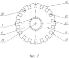
на фиг. 2 - вид сверху ведущего диска рабочего колеса, выполненного согласно изобретению.The invention is illustrated by drawings, which depict:
in FIG. 1 - two sequentially installed steps made in accordance with the claimed invention;
in FIG. 2 is a plan view of a driving wheel of an impeller made in accordance with the invention.
Ступень скважинного многоступенчатого насоса (фиг.1) содержит рабочее колесо 1 и направляющий аппарат 2. Рабочее колесо 1 выполнено с ведомым диском 3, ведущим диском 4, лопастями 5, верхней (в рабочем положении насоса) 6 и боковой 7 поверхностями, втулкой 8, предназначенной для сопряжения через шпонку с общим валом насоса (не изображен). В рабочем колесе образованы каналы, ограниченные жестко связанными между собой ведомым диском 3, лопастями 5 и ведущим диском 4. Направляющий аппарат 2 выполнен с верхним диском 9, нижним диском 10 и лопатками 11, диаметр расположения внешних кромок 12 которых больше диаметра нижнего диска 10 направляющего аппарата 2. Выполненные в направляющем аппарате 2 каналы образованы дисками 9, 10 и лопатками 11. Верхний диск 9 жестко связан с кольцом 13, нижним диском 10 (через лопатки 11) и цапфой 14, сопряженной с втулкой 8 рабочего колеса 1. На диске 3 и 4 закреплены антифрикционные опорные шайбы 15, выполненные, например, из текстолита. На верхней поверхности 6 ведущего диска 4 (фиг.1, 2) выполнены выемки 16, открытые с верхней поверхности 6 ведущего диска 4. Дно 17 каждой выемки 16 выполнено лежащим на поверхности, пересекающей нижнюю поверхность 18 ведущего диска 4 по линии 19, расположенной от оси 20 ведущего диска 4 на расстоянии, меньшем, чем внешний радиус ведущего диска 4 рабочего колеса 1. The stage of a multi-stage borehole pump (Fig. 1) comprises an
Поверхность дна 17 каждой выемки 16 рабочего колеса 1 может быть участком цилиндрической поверхности или выполнена плоской. Боковые стенки 21 и 22 каждой выемки 16 рабочего колеса 1 могут быть выполнены параллельными. The surface of the
В дополнение к выемкам 16, расположенным на ведущем диске 4 рабочего колеса 1, на нижней поверхности 23 нижнего диска 10 направляющего аппарата 2 могут быть выполнены дополнительные выемки 24, открытые с нижней поверхности 23 и внешней боковой поверхности 25 указанного нижнего диска 10. Боковые стенки каждой дополнительной выемки 24 направляющего аппарата 2 могут быть выполнены параллельными. In addition to the
При работе насоса пластовая жидкость поступает в каналы рабочего колеса 1, приводимого в движение валом насоса и, при прохождении потока жидкости через каналы рабочих колес, формируется напор жидкости как за счет центробежных сил, так и за счет действия лопастей рабочего колеса на поток жидкости. Далее жидкость поступает в каналы направляющего аппарата 2, в которых осуществляется создание дополнительного напора и обеспечивается направление потока на рабочее колесо следующей ступени. После выхода из каналов рабочего колеса 1 пластовая жидкость движется потоком, формируемым кольцом 13 направляющего аппарата 2, к каналам направляющего аппарата. В процессе движения выемки 16 вращающегося рабочего колеса 1 формируют тороидальный вихрь, между выходом из каналов рабочего колеса 1 и входом в каналы направляющего аппарата 2. За счет формирования тороидального вихря повышается напор ступени на малых расходах перекачиваемой жидкости, а также осуществляется эффективное перемешивание жидкости с газовыми включениями и диспергация газовых пузырей в перекачиваемой жидкости. Кроме того, при описанном выполнении ступени за счет уменьшения вплоть до нуля толщины дна 17 в зоне линии 19, следовательно, увеличения глубины выемки 16 при приближении к этой линии 19, усиливается вихреобразование в выемках рабочего колеса, повышается количество участвующей в вихревом движении пластовой жидкости, снижается сопротивление внешнего края ведущего диска и улучшается плавность схода пластовой жидкости с поверхности дна выемок рабочего колеса, усиливается диспергация (разбиение) газовых включений в жидкости, повышается напор ступени и стабильность работы. During the operation of the pump, the reservoir fluid enters the channels of the
При цилиндрической форме поверхности дна выемок 16 обеспечивается более плавный сход пластовой жидкости, чем при плоской, однако износ поверхности дна выемок вблизи внешнего края выемок становится более интенсивным. Выполнение боковых стенок выемок 16 рабочего колеса 1 параллельными улучшает стабильность течения пластовой жидкости в пространстве выемок. With a cylindrical shape of the surface of the bottom of the
Выемки 24, сформированные на нижнем диске 10 направляющего аппарата 2, способствуют повышению интенсивности перемещения жидкости в тороидальном вихре и соответственно диспергации газовых включений в газожидкостной смеси. Выполнение боковых стенок выемок 24 направляющего аппарата 2 параллельными и перекрытие выемками 24 линий 19 пересечения поверхностей дна 17 выемок 16 и нижней поверхности 23 рабочего колеса 1 стабилизирует этот процесс. The recesses 24 formed on the lower disk 10 of the guiding apparatus 2 contribute to an increase in the intensity of fluid movement in the toroidal vortex and, accordingly, dispersion of gas inclusions in the gas-liquid mixture. Making the side walls of the recesses 24 of the guide apparatus 2 parallel and overlapping the recesses 24 of the
Источники информации
1. Авторское свидетельство СССР 1617208, кл. F 04 D 29/08; 1990.Sources of information
1. USSR copyright certificate 1617208, cl. F 04 D 29/08; 1990.
2. Патент РФ 2138691, кл. F 04 D 13/10, 1/06, 31/00, 1999. 2. RF patent 2138691, cl. F 04 D 13/10, 1/06, 31/00, 1999.
Claims (6)
Priority Applications (1)
| Application Number | Priority Date | Filing Date | Title |
|---|---|---|---|
| RU2001110144/06A RU2201533C2 (en) | 2001-04-17 | 2001-04-17 | Stage of oil-well multistage pump |
Applications Claiming Priority (1)
| Application Number | Priority Date | Filing Date | Title |
|---|---|---|---|
| RU2001110144/06A RU2201533C2 (en) | 2001-04-17 | 2001-04-17 | Stage of oil-well multistage pump |
Publications (2)
| Publication Number | Publication Date |
|---|---|
| RU2001110144A RU2001110144A (en) | 2003-02-20 |
| RU2201533C2 true RU2201533C2 (en) | 2003-03-27 |
Family
ID=20248456
Family Applications (1)
| Application Number | Title | Priority Date | Filing Date |
|---|---|---|---|
| RU2001110144/06A RU2201533C2 (en) | 2001-04-17 | 2001-04-17 | Stage of oil-well multistage pump |
Country Status (1)
| Country | Link |
|---|---|
| RU (1) | RU2201533C2 (en) |
Cited By (1)
| Publication number | Priority date | Publication date | Assignee | Title |
|---|---|---|---|---|
| RU2303169C1 (en) * | 2005-12-09 | 2007-07-20 | Закрытое Акционерное Общество "Новомет-Пермь" | Centrifugal multi-stepped down-pump |
Citations (6)
| Publication number | Priority date | Publication date | Assignee | Title |
|---|---|---|---|---|
| GB1145895A (en) * | 1966-06-18 | 1969-03-19 | Samuel Pegg And Son Ltd | Centrifugal pump |
| US4278399A (en) * | 1979-06-21 | 1981-07-14 | Kobe, Inc. | Pumping stage for multi-stage centrifugal pump |
| FR2618857A3 (en) * | 1987-08-01 | 1989-02-03 | Bosch Gmbh Robert | Turbopump with a pumping chamber produced in a pump casing, in which is arranged a pump rotor |
| SU1617208A1 (en) * | 1989-02-22 | 1990-12-30 | Всесоюзный Научно-Исследовательский Институт Горной Механики Им.М.М.Федорова | Centrifugal pump |
| RU2133878C1 (en) * | 1997-11-25 | 1999-07-27 | Рабинович Александр Исаакович | Multi-stage submersible pump |
| RU2138691C1 (en) * | 1997-11-25 | 1999-09-27 | Рабинович Александр Исаакович | Stage of submersible multi-stage pump |
-
2001
- 2001-04-17 RU RU2001110144/06A patent/RU2201533C2/en active
Patent Citations (6)
| Publication number | Priority date | Publication date | Assignee | Title |
|---|---|---|---|---|
| GB1145895A (en) * | 1966-06-18 | 1969-03-19 | Samuel Pegg And Son Ltd | Centrifugal pump |
| US4278399A (en) * | 1979-06-21 | 1981-07-14 | Kobe, Inc. | Pumping stage for multi-stage centrifugal pump |
| FR2618857A3 (en) * | 1987-08-01 | 1989-02-03 | Bosch Gmbh Robert | Turbopump with a pumping chamber produced in a pump casing, in which is arranged a pump rotor |
| SU1617208A1 (en) * | 1989-02-22 | 1990-12-30 | Всесоюзный Научно-Исследовательский Институт Горной Механики Им.М.М.Федорова | Centrifugal pump |
| RU2133878C1 (en) * | 1997-11-25 | 1999-07-27 | Рабинович Александр Исаакович | Multi-stage submersible pump |
| RU2138691C1 (en) * | 1997-11-25 | 1999-09-27 | Рабинович Александр Исаакович | Stage of submersible multi-stage pump |
Cited By (1)
| Publication number | Priority date | Publication date | Assignee | Title |
|---|---|---|---|---|
| RU2303169C1 (en) * | 2005-12-09 | 2007-07-20 | Закрытое Акционерное Общество "Новомет-Пермь" | Centrifugal multi-stepped down-pump |
Similar Documents
| Publication | Publication Date | Title |
|---|---|---|
| RU2598501C2 (en) | Impeller blade with improved front edge | |
| WO2016160016A1 (en) | Balance chambers in electric submersible pumps | |
| RU2196252C2 (en) | Stage of oil-well multi-stage centrifugal pump | |
| RU2196253C1 (en) | Centrifugal oil-well pump stage | |
| RU2193692C1 (en) | Stage of oil well centrifugal pump | |
| EP4330517B1 (en) | Helix hub with improved two-phase separation | |
| RU2192561C1 (en) | Stage of submersible centrifugal pump | |
| US10260518B2 (en) | Downhole electrical submersible pump with upthrust balance | |
| RU2133878C1 (en) | Multi-stage submersible pump | |
| CN120292117A (en) | Oil-gas mixed flow pump blade tip leakage flow suppression structure, design method and oil-gas mixed flow pump | |
| RU2186251C2 (en) | Module-section of multistage submersible centrifugal pump | |
| RU2209347C2 (en) | Dispersing stage of submersible multistage centrifugal pump | |
| US8221067B2 (en) | Compact multiphase pump | |
| RU2209345C2 (en) | Stage of multistage submersible centrifugal pump | |
| RU2213887C1 (en) | Stage of submersible centrifugal multistage pump | |
| RU2196255C2 (en) | Centrifugal multi-stage pump impeller | |
| RU2353814C1 (en) | Dispersing stage of submersible multistage centrifugal pump | |
| RU2209346C2 (en) | Stge of multistage sbmersible centrifugal oil-wellpump | |
| RU2192560C2 (en) | Disperser of submersible centrifugal pumping unit | |
| RU2218482C1 (en) | Stage of submersible multistage centrifugal pump | |
| RU2281417C2 (en) | Stage of multistage centrifugal oil-well pump | |
| RU2294458C1 (en) | Multistage submersible centrifugal pump (versions) | |
| RU57395U1 (en) | GUIDING DEVICE FOR STEP OF SUBMERSIBLE CENTRIFUGAL PUMP | |
| RU206623U1 (en) | Guide vane of submersible multistage vane pump | |
| RU2293218C2 (en) | Oil-well centrifugal multistage pump |
Legal Events
| Date | Code | Title | Description |
|---|---|---|---|
| PD4A | Correction of name of patent owner | ||
| PC4A | Invention patent assignment |
Effective date: 20090623 |