RU2201824C2 - Line for making wire - Google Patents
Line for making wire Download PDFInfo
- Publication number
- RU2201824C2 RU2201824C2 RU2001114231/02A RU2001114231A RU2201824C2 RU 2201824 C2 RU2201824 C2 RU 2201824C2 RU 2001114231/02 A RU2001114231/02 A RU 2001114231/02A RU 2001114231 A RU2001114231 A RU 2001114231A RU 2201824 C2 RU2201824 C2 RU 2201824C2
- Authority
- RU
- Russia
- Prior art keywords
- wire
- possibility
- roller
- drive
- rollers
- Prior art date
Links
Images
Landscapes
- Winding, Rewinding, Material Storage Devices (AREA)
Abstract
Description
Изобретение относится к оборудованию для производства проволоки путем продольной резки ленточного материала. The invention relates to equipment for the production of wire by slitting tape material.
Известна линия для производства проволоки, содержащая разматыватель, установку для стыковой сварки, накопитель ленты, правильное устройство, многорядные дисковые ножницы для продольной резки ленты, узел обработки ребер проволоки, блок волок и многосекционное намоточное устройство. Накопитель ленты необходим для обеспечения запаса материала и непрерывности процесса во время установки на разматыватель нового рулона ленты и стыковой сварки ее с концом предыдущего рулона. Блок волок обеспечивает формирование проволоки круглого сечения из прямоугольной (приближенно квадратной) проволоки. Он выполнен подвижным в поперечном направлении от специального привода и является направляющим устройством для осуществления рядовой намотки каждой проволоки на свою секцию намоточного устройства. Между дисковыми ножницами и блоком волок установлен узел обработки проволоки, производящий удаление заусенцев с ребер прямоугольных проволок, образующихся в процессе продольной резки ленты. Обработка ребер производится вращающимся абразивным инструментом, к поверхности которого проволока подводится поочередно каждым ребром посредством системы роликовых направляющих (патент РФ 2102168, В 21 С 1/00, 20.12.95). A known line for the production of wire containing the unwinder, the installation for butt welding, the tape drive, the correct device, multi-row disc shears for longitudinal cutting of the tape, the processing unit of the ribs of the wire, block dies and multi-section winding device. The tape drive is necessary to ensure a supply of material and process continuity during the installation of a new roll of tape on the unwinder and butt welding it with the end of the previous roll. The block of dies provides the formation of round wire from a rectangular (approximately square) wire. It is made movable in the transverse direction from a special drive and is a guiding device for the ordinary winding of each wire on its own section of the winding device. A wire processing unit is installed between the shears and the block of dies, which removes the burrs from the edges of the rectangular wires formed during the longitudinal cutting of the tape. The ribs are machined by a rotating abrasive tool, to the surface of which the wire is fed alternately by each rib by means of a roller guide system (RF patent 2102168, B 21 C 1/00, 12/20/95).
В процессе обработки проволоки происходит ее растяжение, не одинаковое для каждой проволоки. Кроме того, из-за отклонения (в пределах допуска) поперечных размеров проволок диаметры секций намоточного устройства с намотанным на них одинаковым числом витков проволоки будут несколько отличаться. Поскольку все секции барабана вращаются с одинаковой угловой скоростью, то линейные скорости движения отдельных проволок при их намотке будут отличаться пропорционально отклонению диаметров секций. Вследствие этих причин при большом числе одновременно обрабатываемых проволок и длительной непрерывной работе возможна неравномерная плотность намотки проволок и их неодинаковое натяжение намоточным устройством, что отрицательно сказывается на надежности работы линии. In the process of processing the wire, it stretches, which is not the same for each wire. In addition, due to the deviation (within the tolerance) of the transverse dimensions of the wires, the diameters of the sections of the winding device with the same number of turns of wire wound on them will be slightly different. Since all sections of the drum rotate with the same angular velocity, the linear speeds of the individual wires during winding will differ in proportion to the deviation of the diameters of the sections. Due to these reasons, with a large number of simultaneously processed wires and continuous continuous operation, uneven density of the winding wires and their unequal tension by the winding device is possible, which negatively affects the reliability of the line.
Целью изобретения является повышение равномерности намотки проволоки и надежности длительной работы линии. The aim of the invention is to increase the uniformity of the winding wire and the reliability of long-term operation of the line.
Это достигается тем, что в линии для производства проволоки, содержащей разматыватель, установку для стыковой сварки, накопитель ленты, многорядные дисковые ножницы для продольной резки, узел обработки проволоки и намоточное устройство с направляющим механизмом, перед наматывающим устройством расположен многорядный роликовый накопитель проволоки, включающий для каждой проволоки верхнюю ось, установленную в накопителе с возможностью вращения посредством первых подшипников качения, каретку, к которой подвешен груз, установленную с возможностью вертикального перемещения, нижнюю ось, установленную в каретке с возможностью вращения посредством вторых подшипников качения, верхний и нижний наборы роликов, причем каждый ролик установлен соответственно на верхней или нижней оси с возможностью свободного вращения. Каждый ролик в накопителе может быть установлен на оси посредством подшипника качения. Для повышения емкости многорядный накопитель может содержать не менее двух верхних и столько же нижних осей с набором роликов на каждой оси. This is achieved by the fact that in the line for the production of wire containing an unwinder, a butt welding machine, a tape drive, multi-row disc shears for longitudinal cutting, a wire processing unit and a winding device with a guiding mechanism, a multi-row roller wire store is located in front of the winder, including of each wire, the upper axis mounted in the drive with the possibility of rotation by means of the first rolling bearings, a carriage to which a load is mounted, suspended from possibility of vertical movement, a bottom axle mounted in the carriage for rotation by the second rolling bearing, the upper and lower sets of rollers, each roller being mounted respectively on the upper or lower shaft in a freely rotatable. Each roller in the drive can be mounted on an axis by means of a rolling bearing. To increase capacity, a multi-row drive can contain at least two upper and the same number of lower axles with a set of rollers on each axis.
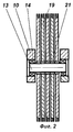
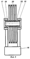
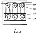
Сущность изобретения поясняется чертежами, где на фиг.1 схематично показана линия для производства проволоки; на фиг.2 и 3 - набор роликов, на фиг. 4 - накопитель для проволоки. The invention is illustrated by drawings, where figure 1 schematically shows a line for the production of wire; in Fig.2 and 3 - a set of rollers, in Fig. 4 - drive for wire.
В линии последовательно расположены разматыватель 1 для размещения рулона 2 ленточного материала 3, устройство 4 для сварки концов ленточного материала встык, накопитель 5 ленты, многорядные дисковые ножницы 6 для резки материала 3 на проволоки 7 и 8 приближенно квадратного сечения, узел 9 обработки ребер проволоки, многорядный роликовый накопитель 10 проволоки и намоточное устройство 11 в виде многосекционного барабана с направляющим механизмом 12, подвижным в поперечном направлении от привода (привод не показан). Для каждой группы 7 и 8 проволок целесообразно иметь в линии свой накопитель 10, направляющий механизм 12 и намоточное устройство 11 (они показаны только для группы проволок 7). При необходимости производства проволоки круглого сечения в качестве направляющего механизма 12 может быть установлен блок волок. An unwinder 1 for placing a roll 2 of tape material 3, a device 4 for welding the ends of the tape material end-to-end, a tape drive 5, multi-row circular shears 6 for cutting material 3 on a wire 7 and 8 of approximately square section, a node 9 for processing wire ribs are sequentially arranged in a line
Многорядный накопитель 10 проволоки содержит для каждой проволоки верхнюю ось 13, установленную в корпусе накопителя посредством первых подшипников качения 14, каретку 15, к которой подвешен груз 16, нижнюю ось 17, установленную в каретке в подшипниках качения 18, верхний и нижний наборы роликов 19 и 20, причем каждый ролик установлен с возможностью свободного вращения соответственно на оси 13 или 17 посредством подшипника скольжения 21 или подшипника качения 22. Подшипники скольжения более просты конструктивно и позволяют сделать накопитель более компактным. Применение подшипников качения с их меньшим трением позволяет уменьшить нагрузку на проволоку, создаваемую накопителем. Каретка 15 может перемещаться по направляющим накопителя (не показаны) вниз под действием веса груза 16 и вверх за счет натяжения проволоки, охватывающей ее ролики 20. The
Емкость многорядного накопителя 10 может быть увеличена в необходимое число раз за счет увеличения количества верхних и нижних осей, оснащенных роликами (на фиг. 4 показан накопитель, имеющий три верхних и три нижних оси). The capacity of the
Работа линии осуществляется следующим образом. На разматыватель 1 устанавливают рулон 2 ленточного материала 4, переднюю кромку которого сваривают встык с задней кромкой предыдущего рулона посредством сварочного устройства 4. Во время установки рулона и сварки работа линии не прекращается, поскольку в накопителе 5 имеется достаточный запас ленточного материала. Далее материал проходит между дисковыми ножами многорядных дисковых ножниц 6 и разрезается на узкие полоски - проволоки приближенно квадратного сечения, причем проволоки через одну отклоняются дисковыми ножами вниз (группа проволок 7), и вверх (группа проволок 8). В узле обработки 9 происходит срезание ребер проволоки и удаление сосредоточенных в этих зонах дефектов (заусенцы и т.п.). The line is as follows. A roll 2 of tape material 4 is installed on the unwinder 1, the front edge of which is butt-welded to the rear edge of the previous roll by means of a welding device 4. During the installation of the roll and welding, the line does not stop, since the drive 5 has a sufficient supply of tape material. Further, the material passes between the circular knives of multi-row circular shears 6 and is cut into narrow strips - wires of approximately square cross section, and the wires through one are deflected by circular knives down (wire group 7) and up (wire group 8). In the processing unit 9, the edges of the wire are cut and the defects concentrated in these zones (burrs, etc.) are removed.
В накопителе 10 проволока поступает последовательно на первый ролик верхнего набора 19, на первый ролик нижнего набора 20, затем на второй ролик верхнего набора и т.д., а с последнего ролика верхнего набора - на секцию намоточного устройства 11, где производится ее рядовая намотка. При использовании в накопителе нескольких верхних и нижних осей (см. фиг.4) проволока с последнего ролика первой верхней оси поступает на расположенный оппозитно ему последний ролик второй оси, т. е. на нечетных верхних и нижних осях заправка проволоки начинается с первого ролика, а на четных осях, наоборот, с последнего ролика. Для подготовки накопителя к работе перед включением линии необходимо вращать барабан намоточного устройства 11 до тех пор, пока каретка 15 вместе с грузом 16 не поднимется в некоторое среднее положение, обеспечивающее равные возможности накопителя на прием и выдачу накопленной проволоки. In the
Для компенсации неравномерности растяжения проволоки и отклонения скорости ее намотки многорядный накопитель отдает имеющиеся запасы проволоки для быстро движущихся проволок, втягивает в себя избыток для проволок, движущихся медленнее, и свободно пропускает проволоки, движущиеся с некоторой средней скоростью, обеспечивая при этом всем проволокам примерно одинаковое натяжение, величина которого зависит, главным образом, от веса груза 16. При работе со средней скоростью движения все ролики 19 и 20 вращаются с одинаковой угловой скоростью, а вместе с ними и с той же скоростью вращаются в своих подшипниках оси 13 и 17. При этом нагрузка на проволоку, создаваемая накопителем, определяется в основном трением в подшипниках качения 14 и 16 и потому невелика. При работе накопителя, отдающего или принимающего проволоку, происходит подъем или опускание каретки 15 с грузом 16, а все ролики верхнего и нижнего набора вращаются с различными скоростями, вследствие чего к вращению осей 13 и 15 добавляется вращение роликов относительно этих осей и нагрузка на проволоку от накопителя увеличивается на величину суммарного трения всех используемых роликов, поэтому для них также является предпочтительным применение подшипников качения. To compensate for the uneven stretching of the wire and the deviation of the speed of its winding, the multi-row drive gives up the available reserves of wire for fast moving wires, draws in excess for wires moving slower, and freely passes wires moving at a certain average speed, while providing all the wires with approximately the same tension , the value of which depends mainly on the weight of the
Claims (3)
Priority Applications (1)
| Application Number | Priority Date | Filing Date | Title |
|---|---|---|---|
| RU2001114231/02A RU2201824C2 (en) | 2001-05-23 | 2001-05-23 | Line for making wire |
Applications Claiming Priority (1)
| Application Number | Priority Date | Filing Date | Title |
|---|---|---|---|
| RU2001114231/02A RU2201824C2 (en) | 2001-05-23 | 2001-05-23 | Line for making wire |
Publications (1)
| Publication Number | Publication Date |
|---|---|
| RU2201824C2 true RU2201824C2 (en) | 2003-04-10 |
Family
ID=20250042
Family Applications (1)
| Application Number | Title | Priority Date | Filing Date |
|---|---|---|---|
| RU2001114231/02A RU2201824C2 (en) | 2001-05-23 | 2001-05-23 | Line for making wire |
Country Status (1)
| Country | Link |
|---|---|
| RU (1) | RU2201824C2 (en) |
Cited By (1)
| Publication number | Priority date | Publication date | Assignee | Title |
|---|---|---|---|---|
| RU2467814C1 (en) * | 2011-06-29 | 2012-11-27 | Владимир Николаевич Стазаев | V stazaev's belt accumulator |
Citations (3)
| Publication number | Priority date | Publication date | Assignee | Title |
|---|---|---|---|---|
| RU2102168C1 (en) * | 1995-12-20 | 1998-01-20 | Стазаев Владимир Николаевич | Wire production line |
| RU2112615C1 (en) * | 1996-09-18 | 1998-06-10 | Челябинский государственный технический университет | Rectangular shape drawing process |
| RU2149225C1 (en) * | 1996-04-18 | 2000-05-20 | Электрокоппер Продактс Лимитед | Wire manufacturing method |
-
2001
- 2001-05-23 RU RU2001114231/02A patent/RU2201824C2/en not_active IP Right Cessation
Patent Citations (3)
| Publication number | Priority date | Publication date | Assignee | Title |
|---|---|---|---|---|
| RU2102168C1 (en) * | 1995-12-20 | 1998-01-20 | Стазаев Владимир Николаевич | Wire production line |
| RU2149225C1 (en) * | 1996-04-18 | 2000-05-20 | Электрокоппер Продактс Лимитед | Wire manufacturing method |
| RU2112615C1 (en) * | 1996-09-18 | 1998-06-10 | Челябинский государственный технический университет | Rectangular shape drawing process |
Non-Patent Citations (1)
| Title |
|---|
| КОКОВИХИН Ю.И. Технология волочильного производства. - Свердловск, 1979. * |
Cited By (1)
| Publication number | Priority date | Publication date | Assignee | Title |
|---|---|---|---|---|
| RU2467814C1 (en) * | 2011-06-29 | 2012-11-27 | Владимир Николаевич Стазаев | V stazaev's belt accumulator |
Similar Documents
| Publication | Publication Date | Title |
|---|---|---|
| DE3522271A1 (en) | DEVICE FOR REWINDING A RAILWAY | |
| EP2246160B1 (en) | Device and method for cutting sheet-like or strip-like tissue or non-woven fabric material which allows air to penetrate | |
| SE451963B (en) | CONSTRUCTION ELEMENTS IN THE FORM OF A LONG STRENGTH METAL RANGE WITH LONG-TERM DIVIDING SLOTS | |
| DE69814882T2 (en) | COMBINATION OF 5-HT RECOVERY INHIBITORS AND H5-HT 1B ANTAGONISTS OR PARTIAL AGONISTS | |
| EP0145029A2 (en) | Winding or unwinding device with a plurality of mandrels in cascade | |
| CN107891106A (en) | A kind of cable cutting production line | |
| DE2325794A1 (en) | WINDING DEVICE | |
| CN105377460A (en) | Loop absorber for slitting lines | |
| US3412950A (en) | Cloth roll feeding apparatus | |
| CN119216782A (en) | A laser welding machine for alloy resistance | |
| RU2201824C2 (en) | Line for making wire | |
| CN1189260C (en) | Coiling controlling method | |
| FI109195B (en) | Rolling device for paper and board paths | |
| US3679521A (en) | Driven mandrel rotatable about its longitudinal axis | |
| DE2425463B1 (en) | Working process for further processing of profile steel following a fine steel rolling mill and arrangement for carrying out the process | |
| CN210558434U (en) | Adjustable film slitting machine | |
| US6748781B2 (en) | Device for producing metal fibers | |
| US817026A (en) | Paper-winding machine. | |
| RU2235617C1 (en) | Wire production line | |
| CN214217584U (en) | Steel band side cut slitting direction coiling mechanism | |
| DE3016911A1 (en) | Winding fabric on to alternately driven rolls - via vertically movable guide and cutter head horizontally movable to above winding shafts | |
| RU2082518C1 (en) | Apparatus for coiling strip | |
| RU2287388C1 (en) | Wire production line | |
| US1641866A (en) | Core-tube cutter | |
| IT1302793B1 (en) | DEVICE FOR FORMING THE SPOOLS IN A LAMINATED PRODUCT MACHINE |
Legal Events
| Date | Code | Title | Description |
|---|---|---|---|
| MM4A | The patent is invalid due to non-payment of fees |
Effective date: 20040524 |
|
| NF4A | Reinstatement of patent | ||
| MM4A | The patent is invalid due to non-payment of fees |
Effective date: 20070524 |