RU2201860C2 - Workpiece feeder - Google Patents
Workpiece feeder Download PDFInfo
- Publication number
- RU2201860C2 RU2201860C2 RU2001111607A RU2001111607A RU2201860C2 RU 2201860 C2 RU2201860 C2 RU 2201860C2 RU 2001111607 A RU2001111607 A RU 2001111607A RU 2001111607 A RU2001111607 A RU 2001111607A RU 2201860 C2 RU2201860 C2 RU 2201860C2
- Authority
- RU
- Russia
- Prior art keywords
- compressed air
- vacuum
- parts
- source
- transportation
- Prior art date
Links
Images
Landscapes
- Manipulator (AREA)
Abstract
Description
Изобретение относится к устройствам подачи деталей с использованием систем вакуумных захватов для межоперационного транспортирования деталей. The invention relates to parts feeding devices using vacuum gripper systems for inter-operative transportation of parts.
Известно устройство для подачи деталей захватными вакуумными камерами, установленными на транспортирующем узле с приводом от гидроцилиндра, имеющими возможность самоустановки относительно поверхности детали и соединенными с вакуумирующей полостью эжектора. При подаче каждой детали захватными вакуумными камерами все устройство перемещается на величину хода транспортирующего узла, ограниченного шагом подачи детали. A device for feeding parts by gripping vacuum chambers mounted on a conveying unit driven by a hydraulic cylinder, having self-alignment relative to the surface of the part and connected to the evacuating cavity of the ejector, is known. When each part is fed by gripping vacuum chambers, the entire device moves by the amount of travel of the conveying unit, limited by the pitch of the part.
Недостатком указанного устройства является наличие транспортирующего узла с величиной хода, ограниченного шагом подачи, исключающим возможность подачи нескольких деталей за один рабочий цикл на расстояние, превышающее ход транспортирующего узла, тем самым снижаются технологические возможности при межоперационной подаче деталей (А. с. СССР 312734, В 23 Q 7/04, 1971). The disadvantage of this device is the presence of a transporting unit with a stroke limited by the feed pitch, which excludes the possibility of supplying several parts in one working cycle to a distance exceeding the stroke of the transporting unit, thereby reducing technological capabilities during interoperational supply of parts (A. S. USSR 312734, B 23
Наиболее близким из известных технических решений является устройство для подачи деталей, содержащее основание, расположенные на нем вакуумные захваты с рядами сопел, образующими несущую поверхность, установленными на расстоянии, соответствующем размерам подаваемой детали, при этом каждый вакуумный захват выполнен в виде смежно расположенных основной и дополнительной камер, связанных с кулачковым механизмом. При подаче детали вакуумными захватами происходит перехват детали между захватами в момент их полной остановки с последующим транспортированием на величину хода вакуумных захватов, что в целом приводит к снижению средней скорости транспортирования деталей. The closest known technical solution is a device for feeding parts, containing a base, vacuum grips located on it with rows of nozzles forming a bearing surface, installed at a distance corresponding to the dimensions of the supplied part, with each vacuum gripper made in the form of adjacent primary and secondary cameras associated with the cam mechanism. When a component is fed with vacuum grippers, the component is intercepted between the grippers at the moment of their complete stop, followed by transportation by the stroke size of the vacuum grippers, which generally leads to a decrease in the average transportation speed of the parts.
Недостатком данного устройства является конструктивное исполнение вакуумных захватов, при котором надежное транспортирование детали возможно только при наличии у нее двух плоских поверхностей, а перехват детали вакуумными захватами происходит в момент полной их остановки, что снижает среднюю скорость транспортирования деталей в устройстве, при этом величина перемещения детали в направлении транспортирования за время перемещения вакуумными захватами на шаг подачи не превышает величину хода вакуумных захватов, что снижает производительность устройства в целом (патент РФ 2147503, В 23 Q 7/04, 20.04.2000). The disadvantage of this device is the design of vacuum grippers, in which reliable transportation of the part is possible only if it has two flat surfaces, and the interception of the part by vacuum grippers occurs at the moment of their complete stop, which reduces the average speed of transportation of parts in the device, while the amount of movement of the part in the direction of transportation during the movement of the vacuum grippers on the feed step does not exceed the magnitude of the stroke of the vacuum grippers, which reduces production the entire device (patent of the Russian Federation 2147503, 23
Данное устройство имеет низкий технический уровень, что обусловлено конструктивным исполнением транспортирующего узла на базе вакуумного захвата, так как подача деталей происходит при перехвате детали между вакуумными захватами с последующим транспортированием на величину хода вакуумных захватов. В результате происходит подача деталей за один рабочий ход на расстояние, не превышающее величину хода транспортирующего узла, тем самым ограничивается шаг подачи детали и снижаются технологические возможности при межоперационной подаче деталей. This device has a low technical level, which is due to the design of the transporting unit on the basis of vacuum grippers, since the supply of parts occurs when intercepting the part between the vacuum grippers with subsequent transportation by the stroke size of the vacuum grippers. As a result, parts are fed in one working stroke to a distance not exceeding the stroke of the transporting unit, thereby limiting the step of feeding the part and reducing technological capabilities during inter-operative supply of parts.
Важнейшей задачей данного изобретения является создание новой конструкции транспортирующего узла с новой системой взаимодействия вакуумных захватов с транспортируемыми деталями с поочередным согласованием операций захвата деталей и подачи их за один рабочий ход на величину, превышающую ход транспортирующего узла, работающих в едином цикле с камерой нагнетания, удерживающей детали над несущей поверхностью в период холостого хода цикла за счет поочередного подключения к источнику сжатого воздуха камеры нагнетания посредством устройства подачи сжатого воздуха, что обеспечивает увеличение скорости транспортирования деталей при межоперационной подаче, тем самым повышаются технологические возможности устройства. The most important objective of this invention is the creation of a new design of the conveying unit with a new system for the interaction of vacuum grippers with the transported parts with sequential coordination of the operations of gripping the parts and supplying them in one working stroke by an amount exceeding the stroke of the conveying unit working in a single cycle with the injection chamber holding the parts above the bearing surface during the idle cycle of the cycle by alternately connecting the discharge chamber to the source of compressed air by means of a device CTBA compressed air that provides increased conveying speed parts when feeding interoperational thereby increased technological capabilities of the device.
Техническим результатом заявленного устройства является новая технологическая схема подачи деталей с рабочим циклом, реализующая новое взаимодействие вакуумных захватов и камеры нагнетания в процессе непрерывной подачи, что обеспечивает надежный захват с непрерывным перемещением деталей на величину, превышающую ход транспортирующего узла, позволяет повысить среднюю скорость транспортирования деталей и расширить функциональные возможности устройства в целом. The technical result of the claimed device is a new technological scheme for supplying parts with a duty cycle, realizing a new interaction of vacuum grippers and a pressure chamber during continuous feeding, which ensures reliable gripping with continuous movement of parts by an amount exceeding the travel of the conveying unit, which allows to increase the average transportation speed of parts and expand the functionality of the device as a whole.
Технический результат достигается тем, что устройство для подачи деталей содержит основание, расположенные на нем и соединенные с источником вакуума вакуумные захваты с рядами сопел, образующих несущую поверхность для удержания деталей, и привод возвратно-поступательного движения основания, при этом оно снабжено установленным на основании и связанным с приводом возвратно-поступательного движения транспортирующим узлом, величина хода которого меньше величины подачи детали за один рабочий ход, и выполненной между вакуумными захватами и соединенной с источником сжатого воздуха посредством устройства подачи сжатого воздуха камерой нагнетания с рядом сопел для формирования подъемной силы, величина которой превышает величину притягивающей силы вакуумных захватов, с образованием зоны избыточного давления над несущей поверхностью, при этом вакуумные захваты соединены с источником вакуума посредством выполненных в транспортирующем узле каналов и расположены в нем симметрично относительно камеры нагнетания, а устройство подачи сжатого воздуха выполнено в виде пневмоклапана, датчика ускорения транспортирующего узла для коммутирования источника сжатого воздуха с камерой нагнетания в момент достижения транспортирующим узлом максимальной скорости в направлении транспортирования деталей и элемента задержки времени для отключения камеры нагнетания от источника сжатого воздуха. The technical result is achieved by the fact that the device for feeding parts contains a base located on it and connected to a vacuum source, vacuum grippers with rows of nozzles forming a bearing surface for holding parts, and a reciprocating drive of the base, while it is equipped with mounted on the base and a transporting unit connected to the reciprocating drive, the stroke of which is less than the feed rate of the part in one working stroke, and made between the vacuum grippers and connected to a source of compressed air by means of a compressed air supply device with an injection chamber with a series of nozzles for generating a lifting force, the magnitude of which exceeds the attractive force of the vacuum grippers, with the formation of an overpressure zone above the bearing surface, while the vacuum grippers are connected to the vacuum source by means of the transporting unit of the channels and are located therein symmetrically with respect to the discharge chamber, and the compressed air supply device is made in the form of pneumatic paw acceleration sensor carrier unit for switching the compressed air source to the discharge chamber upon reaching the maximum speed conveying unit in the conveying direction of parts and the time delay element to disable the discharge chamber from the compressed air source.
Создание новой конструкции транспортирующего узла с системой вакуумных захватов, камеры нагнетания с рядом сопел и устройства подачи сжатого воздуха обеспечивает новую технологическую схему взаимодействия транспортирующего узла с подаваемыми деталями с поочередным согласованием операций захвата и подачи их за один основной ход на величину, превышающую ход транспортирующего узла. The creation of a new design of the conveying unit with a vacuum gripper system, a discharge chamber with a number of nozzles and a compressed air supply device provides a new technological scheme for the interaction of the conveying unit with the supplied parts, with the subsequent matching of the capture and supply operations for one main stroke by an amount exceeding the conveyor unit's stroke.
Введена камера нагнетания с рядом сопел, формирующая подъемную силу, приложенную к транспортируемой детали, величина которой превышает притягивающую силу, приложенную к детали со стороны вакуумных захватов, тем самым достигается надежное удержание детали над несущей поверхностью транспортирующего узла в период холостого хода рабочего цикла устройства. An injection chamber has been introduced with a series of nozzles, which forms a lifting force applied to the transported part, the value of which exceeds the attractive force applied to the part from the side of the vacuum grippers, thereby achieving reliable retention of the part above the bearing surface of the transporting unit during the idle period of the device operating cycle.
Введено устройство подачи сжатого воздуха, выполненное в виде пневмоклапана, датчика ускорения транспортирующего узла и элемента задержки времени, тем самым обеспечивается взвешивание деталей над несущей поверхностью в момент достижения транспортирующим узлом максимальной скорости в направлении транспортирования и создание условий для движения детали в этом направлении в период холостого хода транспортирующего узла посредством создания зоны избыточного давления над несущей поверхностью и уменьшения коэффициента трения скольжения в несколько раз. A compressed air supply device has been introduced, made in the form of a pneumatic valve, an acceleration sensor of the transporting unit and a time delay element, thereby weighing parts above the bearing surface when the transporting unit reaches its maximum speed in the transport direction and creating conditions for the part to move in this direction during the idle period the course of the transporting unit by creating a zone of excess pressure above the bearing surface and reducing the coefficient of friction I several times.
Проведенный заявителем анализ уровня техники, включающий поиск по патентным и научно-техническим источникам информации и выявление источников, содержащих сведения об аналогах заявленного изобретения, позволяет установить, что заявителем не обнаружен аналог, характеризующийся признаками, идентичными всем осуществленным признакам заявленного изобретения, а определение из перечня выявленных аналогов прототипа как наиболее близкого по совокупности признаков аналога позволяет выявить совокупность существенных по отношению к усматриваемому техническому результату отличительных признаков в заявленном объекте, изложенном в формуле изобретения. The analysis of the prior art by the applicant, including a search by patent and scientific and technical sources of information and identification of sources containing information about analogues of the claimed invention, allows us to establish that the applicant has not found an analogue characterized by features identical to all implemented features of the claimed invention, and the definition from the list identified analogues of the prototype as the closest in the totality of the features of the analogue allows you to identify the set of essential in relation to seeing The technical result of the distinguishing features in the claimed object set forth in the claims.
Следовательно, заявленное изобретение соответствует требованию "новизна" по действующему законодательству. Therefore, the claimed invention meets the requirement of "novelty" under applicable law.
Для проверки соответствия заявленного изобретения требованию изобретательского уровня заявитель провел дополнительный поиск известных решений с целью выявления признаков, совпадающих с отличительными от прототипа признаками заявленного изобретения, результат которого показывает, что заявленное изобретение не следует для специалистов явным образом из известного уровня техники. To verify the conformity of the claimed invention to the requirements of the inventive step, the applicant conducted an additional search for known solutions in order to identify features that match the distinctive features of the claimed invention, the result of which shows that the claimed invention does not follow explicitly from the prior art.
Следовательно, заявленное изобретение соответствует требованию "изобретательский уровень". Therefore, the claimed invention meets the requirement of "inventive step".
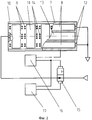
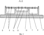
Данное устройство представлено на чертежах: фиг. 1 - общий вид устройства; фиг.2 - вид сверху транспортирующего узла устройства; фиг.3 - разрез А-А на фиг.1. This device is shown in the drawings: FIG. 1 - general view of the device; figure 2 is a top view of the transporting node of the device; figure 3 - section aa in figure 1.
Устройство для подачи деталей содержит нижнюю массу 1, основание 2, привод возвратно-поступательного движения, выполненный в виде установленного на нижней массе пневматического вибратора 3, шток 4 которого соединен с кронштейном 5, закрепленным на основании 2, подвешенном на пружинных стержнях 6, закрепленных на нижней массе 1 (фиг.1). На основании 2 установлен связанный с приводом возвратно-поступательного движения транспортирующий узел 7, в котором размещены симметрично расположенные, соединенные с источником вакуума посредством каналов в транспортирующем узле 7 вакуумные захваты 8 с рядами сопел 9, образующие несущую поверхность 10, при этом расстояние между соседними соплами 9 не превышает размеров подаваемой детали 11 (фиг. 2, 3). Основание 2 на подвесках из пружинных стержней 6, вместе с транспортирующим узлом 7, под действием пневматического вибратора 3 имеет возможность совершать возвратно-поступательное движение. The device for supplying parts contains a lower mass 1, a
Каждый вакуумный захват 8 соединен с источником вакуума посредством канала 12 и образует на несущей поверхности 10 зону захвата в период всего рабочего цикла, а между вакуумными захватами 8 выполнена камера нагнетания 13 с рядом сопел 14 для формирования подъемной силы, соединенная с источником сжатого воздуха при помощи устройства подачи сжатого воздуха, выполненного в виде пневмоклапана 15, датчика ускорения 16 транспортирующего узла, элемента задержки времени 17. При подаче деталей 11 величина хода транспортирующего узла 7 равна основному ходу рабочего цикла и определяется жесткостью упругих стержней 6 и пневматическим вибратором 3, что обеспечивает захват деталей вакуумными захватами 8 и перемещение их совместно с транспортирующим узлом 7 в период основного хода рабочего цикла. При достижении транспортирующим узлом 7 максимальной скорости в направлении транспортирования деталей датчик ускорения 16 транспортирующего узла вырабатывает управляющий импульс, переключающий пневмоклапан 15 для коммутирования источника сжатого воздуха с камерой нагнетания 13 и, одновременно этим же импульсом запускает элемент задержки времени 17. Посредством струй сжатого воздуха, истекающих из камеры нагнетания 13, формируется подъемная сила, действующая на транспортируемую деталь 11, при этом величина подъемной силы превышает притягивающую силу, действующую на деталь со стороны вакуумных захватов 8, что обеспечивает создание зоны избыточного давления над несущей поверхностью 10 транспортирующего узла 3 и отрыв детали от нее и поддержание детали во взвешенном состоянии на период холостого хода рабочего цикла устройства, при этом величина хода транспортирующего узла меньше величины подачи детали за один рабочий ход. Each
По окончании перемещения на величину основного хода цикла транспортирующий узел 7 начинает перемещаться под действием пружинных стержней 6 в направлении, противоположном направлению транспортирования деталей, что соответствует холостому ходу рабочего цикла, и после достижения транспортирующим узлом 7 крайнего положения в этом движении элемент задержки времени 17 формирует управляющий импульс, переключающий пневмоклапан 15 в закрытое состояние, что обеспечивает отсоединение камеры нагнетания 13 от источника сжатого воздуха и захват транспортируемой детали вакуумными захватами 8. При этом транспортирующий узел 7 уже движется в направлении транспортирования деталей, то есть совершает основной ход рабочего цикла устройства. Таким образом, посредством чередования основного и холостого ходов цикла обеспечивается непрерывный рабочий цикл подачи деталей. At the end of the movement by the amount of the main course of the cycle, the transporting
Введение камеры нагнетания 13 с рядом сопел 14, формирующей подъемную силу, действующую на транспортируемую деталь, и величина которой превышает величину притягивающей силы, действующей на деталь со стороны вакуумных захватов 8, обеспечивает надежное удержание деталей над несущей поверхностью в период холостого хода цикла работы устройства. The introduction of the
Введение устройства подачи сжатого воздуха, выполненного в виде пневмоклапана 15, управляемого датчиком ускорения 16 транспортирующего узла и элементом задержки времени 17, имеющего возможность регулирования продолжительности интервала времени подачи сжатого воздуха в камеру нагнетания 13, обеспечивает взвешивание деталей в момент достижения транспортирующим узлом максимальной скорости в направлении транспортирования, что обеспечивает повышение скорости транспортирования деталей и, следовательно, производительности устройства в целом. The introduction of a compressed air supply device, made in the form of a
Устройство работает следующим образом. The device operates as follows.
Устройство для подачи деталей выполнено в виде транспортирующего узла 7, содержащего вакуумные захваты 8 и камеру нагнетания 13 с рядом сопел 14 и установленного на основании 2. Основание 2 закреплено на подвесках из пружинных стрежней 6 на нижней массе 1. Транспортирующий узел 7 вместе с основанием 2 на подвесках из пружинных стержней 6 имеет возможность совершать возвратно-поступательное движение под действием пневматического вибратора 3 (фиг.1, 2, 3). The device for supplying parts is made in the form of a transporting
В исходном состоянии устройства транспортирующий узел 7 под действием пневматического вибратора 3 перемещается в направлении, противоположном направлению транспортирования деталей 11, то есть совершает холостой ход рабочего цикла. При перемещении транспортирующего узла 7 от исходного положения камера нагнетания 13 соединена пневмоклапаном 15 с источником сжатого воздуха, а элемент задержки времени 17 отсчитывает интервал времени, за который транспортирующий узел 7 выполнит холостой ход рабочего цикла и снова наберет скорость движения в направлении транспортирования деталей. При этом вакуумные захваты 8 подключены посредством каналов 12 к источнику вакуума в течение всего рабочего цикла. Транспортируемая деталь 11 находится во взвешенном состоянии над несущей поверхностью 10 транспортирующего узла 7, так как величина подъемной силы, приложенной к детали и формируемой истекающими струями сжатого воздуха из сопел 14 камеры нагнетания 13, превышает притягивающую силу, так же приложенную к ней со стороны вакуумных захватов 8. Таким образом, над несущей поверхностью 10 транспортирующего узла 7 образуется зона избыточного давления, уменьшающая силы сопротивления движению детали и коэффициент трения скольжения в несколько раз, что обеспечивает взаимное относительное движение транспортирующего узла 7 и детали 11 в противоположных направлениях. In the initial state of the device, the
При перемещении транспортирующего узла 7, совершающего холостой ход рабочего цикла, до крайнего положения в этом движении транспортирующий узел 7 под действием пневматического вибратора 3 изменяет направление движения и начинает перемещаться в направлении транспортирования деталей, совершая основной ход рабочего цикла. Элемент задержки времени 17 вырабатывает управляющий импульс, который переключает пневмоклапан 15 в закрытое состояние, что обеспечивает отсоединение камеры нагнетания 13 от источника сжатого воздуха. Истечение сжатого воздуха над несущей поверхностью 10 из ее сопел 14 прекращается, что приводит к захвату детали 11 вакуумными захватами 8 вследствие отсутствия подъемной силы и увеличению коэффициента трения скольжения между поверхностью детали 11 и несущей поверхностью 10, что приводит к увеличению сил сопротивления относительному движению детали 11 и транспортирующего узла 7. Деталь 11 начинает двигаться в направлении транспортирования вместе с транспортирующим узлом 7 без проскальзывания. При достижении транспортирующим узлом 7 максимальной скорости в направлении транспортирования, которая фиксируется датчиком ускорения 16 транспортирующего узла, кинетическая энергия движения детали 11 имеет максимальное значение. Датчик ускорения 16 вырабатывает управляющий импульс, который переключает пневмоклапан 15 в открытое состояние и камера нагнетания 13 коммутируется с источником сжатого воздуха. Этим же управляющим импульсом запускается элемент задержки времени 17. Над несущей поверхностью 10 транспортирующего узла 7 образуется зона избыточного давления, отрывающая деталь 11 от несущей поверхности 10 и приводящая к снижению сил сопротивления движению в направлении транспортирования деталей и сохранению деталью 11 накопленной кинетической энергии в период холостого хода цикла. Под действием сил инерции деталь 11 продолжает двигаться в направлении транспортирования независимо от скорости и направления движения транспортирующего узла 7. А так как зона избыточного давления уменьшает силы сопротивления такому движению, то рассеивание кинетической энергии детали 11 происходит гораздо медленнее и деталь практически сохраняет скорость своего движения, соответствующую максимальной скорости транспортирующего узла 7. Это приводит к тому, что перемещение детали 11 в период холостого хода транспортирующего узла 7 превышает ход транспортирующего узла, что обеспечивает увеличение средней скорости транспортирования детали в устройстве и повышение производительности устройства в целом. When moving the transporting
Зона избыточного давления будет сохраняться до того момента времени, когда элемент задержки времени 17 не выработает управляющий импульс, переключающий пневмоклапан 15 в закрытое состояние. Величина времени задержки возврата пневмоклапана 15 в закрытое состояние определяется элементом задержки времени 17 и регламентируется периодом времени, за который транспортирующий узел 7 совершит холостой ход, перейдет в основной ход и наберет скорость, соизмеримую с остаточной скоростью движущейся детали. Далее рабочий цикл подачи повторяется многократно, обеспечивая непрерывную подачу деталей в заданном направлении. The overpressure zone will be maintained until the time when the
Таким образом, вышеизложенное свидетельствует о выполнении при использовании заявленного изобретения следующей совокупности условий:
- устройство для подачи деталей с системой вакуумных захватов, работающих в едином цикле с камерой нагнетания и устройством подачи сжатого воздуха и обеспечивающих новую систему взаимодействия с транспортируемыми деталями с поочередным согласованием операций захвата деталей и подачи их за один рабочий ход на величину, превышающую ход транспортирующего узла посредством удержания детали над несущей поверхностью в период холостого хода цикла за счет подключения камеры нагнетания к источнику сжатого воздуха при помощи устройства подачи сжатого воздуха, предназначено для подачи деталей по новой технологической схеме, обеспечивающей надежный захват и непрерывное перемещение деталей, позволяет повысить среднюю скорость транспортирования деталей и расширить функциональные возможности устройства;
- для заявленного изобретения, в том виде как оно охарактеризовано в формуле изобретения, подтверждена возможность его осуществления в соответствии с описанием и прилагаемыми чертежами;
- разработанное устройство, воплощающее заявленное изобретение, при его осуществлении способно обеспечить достижение усматриваемого технического результата.Thus, the foregoing indicates that when using the claimed invention the following set of conditions:
- a device for supplying parts with a vacuum gripper system operating in a single cycle with a discharge chamber and a compressed air supply device and providing a new system for interacting with transported parts with sequential coordination of operations for gripping parts and supplying them in one working stroke by an amount exceeding the travel of the conveying unit by holding the part above the bearing surface during the idle cycle by connecting the discharge chamber to a source of compressed air using a feed device compressed air, designed to supply parts according to a new technological scheme, which provides reliable capture and continuous movement of parts, allows to increase the average speed of transportation of parts and expand the functionality of the device;
- for the claimed invention, in the form as described in the claims, the possibility of its implementation in accordance with the description and the attached drawings is confirmed;
- the developed device embodying the claimed invention, in its implementation is able to ensure the achievement of the perceived technical result.
Следовательно, заявленное изобретение соответствует требованию "промышленная применимость". Therefore, the claimed invention meets the requirement of "industrial applicability".
Claims (1)
Priority Applications (1)
| Application Number | Priority Date | Filing Date | Title |
|---|---|---|---|
| RU2001111607A RU2201860C2 (en) | 2001-04-26 | 2001-04-26 | Workpiece feeder |
Applications Claiming Priority (1)
| Application Number | Priority Date | Filing Date | Title |
|---|---|---|---|
| RU2001111607A RU2201860C2 (en) | 2001-04-26 | 2001-04-26 | Workpiece feeder |
Publications (2)
| Publication Number | Publication Date |
|---|---|
| RU2001111607A RU2001111607A (en) | 2003-01-20 |
| RU2201860C2 true RU2201860C2 (en) | 2003-04-10 |
Family
ID=20249108
Family Applications (1)
| Application Number | Title | Priority Date | Filing Date |
|---|---|---|---|
| RU2001111607A RU2201860C2 (en) | 2001-04-26 | 2001-04-26 | Workpiece feeder |
Country Status (1)
| Country | Link |
|---|---|
| RU (1) | RU2201860C2 (en) |
Citations (4)
| Publication number | Priority date | Publication date | Assignee | Title |
|---|---|---|---|---|
| SU825924A1 (en) * | 1979-08-09 | 1981-04-30 | Vni Pi Tugoplavkikh Metall | Mining machine cutter bit |
| US4453347A (en) * | 1980-12-13 | 1984-06-12 | Hauni-Werke Korber & Co. Kg. | Apparatus for manipulating workpieces having plane parallel surfaces |
| DE3830685C1 (en) * | 1988-09-09 | 1989-08-24 | Horst Witte Entwicklungs- Und Vertriebs Kg, 2122 Bleckede, De | |
| RU2147503C1 (en) * | 1998-06-16 | 2000-04-20 | Волгоградский государственный технический университет | Part feeding device |
-
2001
- 2001-04-26 RU RU2001111607A patent/RU2201860C2/en active
Patent Citations (4)
| Publication number | Priority date | Publication date | Assignee | Title |
|---|---|---|---|---|
| SU825924A1 (en) * | 1979-08-09 | 1981-04-30 | Vni Pi Tugoplavkikh Metall | Mining machine cutter bit |
| US4453347A (en) * | 1980-12-13 | 1984-06-12 | Hauni-Werke Korber & Co. Kg. | Apparatus for manipulating workpieces having plane parallel surfaces |
| DE3830685C1 (en) * | 1988-09-09 | 1989-08-24 | Horst Witte Entwicklungs- Und Vertriebs Kg, 2122 Bleckede, De | |
| RU2147503C1 (en) * | 1998-06-16 | 2000-04-20 | Волгоградский государственный технический университет | Part feeding device |
Similar Documents
| Publication | Publication Date | Title |
|---|---|---|
| JP4026773B2 (en) | Method and apparatus for gripping and moving food | |
| CN110267776B (en) | End effector assembly | |
| US20180029807A1 (en) | Suction device | |
| US10421621B2 (en) | Work transferring system and work transferring method | |
| CN1827316A (en) | Robot hand and conveying robot | |
| KR101956300B1 (en) | Griffer for metal product using permanent magnet and metal product loading system using this | |
| US3528575A (en) | Feed and transfer systems | |
| KR20220120210A (en) | needle gripper device for fabric transfer | |
| EP3423208B1 (en) | Method for automatically picking metallic elements of elongated shape and picking device | |
| CN210848583U (en) | Material receiving mechanism of plate shearing machine | |
| RU2001111607A (en) | DEVICE FOR FEEDING PARTS | |
| RU2147503C1 (en) | Part feeding device | |
| US20040231144A1 (en) | Device for supplying a connecting element to a processing unit and method of supplying the connecting element | |
| CN113305014A (en) | Commodity circulation letter sorting is with small-size intelligent arm | |
| US4424185A (en) | Part pick-up mechanism for powder compacting presses and the like | |
| CN109987383B (en) | Metal sheet conveyer | |
| JPH07115727B2 (en) | Intermittent supply device for goods | |
| SU1627404A1 (en) | Magneto-vacuum grip | |
| KR102683324B1 (en) | Spring automatic insertion device | |
| CN218464856U (en) | Regular conveying mechanism of rod and rod processing production line | |
| KR100605306B1 (en) | Pneumatic conveyor | |
| CN111977386B (en) | Integrated transmission system for sheet metal processing machinery | |
| RU2691155C1 (en) | Vacuum gripping aggregate module | |
| JP2545532B2 (en) | Conveyor equipment | |
| CN210392631U (en) | Special aluminum sheet collecting equipment |