RU2217110C2 - Instrument for exfoliation of cornea - Google Patents
Instrument for exfoliation of cornea Download PDFInfo
- Publication number
- RU2217110C2 RU2217110C2 RU2000126936/14A RU2000126936A RU2217110C2 RU 2217110 C2 RU2217110 C2 RU 2217110C2 RU 2000126936/14 A RU2000126936/14 A RU 2000126936/14A RU 2000126936 A RU2000126936 A RU 2000126936A RU 2217110 C2 RU2217110 C2 RU 2217110C2
- Authority
- RU
- Russia
- Prior art keywords
- tool
- instrument
- working part
- cornea
- tool according
- Prior art date
Links
- 210000004087 cornea Anatomy 0.000 title abstract description 13
- 238000004299 exfoliation Methods 0.000 title abstract description 5
- 208000001491 myopia Diseases 0.000 claims abstract description 6
- 230000004379 myopia Effects 0.000 claims abstract description 6
- 238000009434 installation Methods 0.000 claims abstract description 3
- 230000015572 biosynthetic process Effects 0.000 claims description 3
- 206010064489 Corneal exfoliation Diseases 0.000 claims description 2
- 230000000007 visual effect Effects 0.000 claims description 2
- 238000012544 monitoring process Methods 0.000 claims 1
- 239000003814 drug Substances 0.000 abstract description 2
- 239000011229 interlayer Substances 0.000 abstract description 2
- 230000000694 effects Effects 0.000 abstract 1
- 239000000126 substance Substances 0.000 abstract 1
- 238000011179 visual inspection Methods 0.000 abstract 1
- 239000000560 biocompatible material Substances 0.000 description 3
- 208000014674 injury Diseases 0.000 description 3
- 230000008733 trauma Effects 0.000 description 3
- 230000037431 insertion Effects 0.000 description 2
- 238000003780 insertion Methods 0.000 description 2
- 208000028006 Corneal injury Diseases 0.000 description 1
- 210000005252 bulbus oculi Anatomy 0.000 description 1
- 239000007943 implant Substances 0.000 description 1
- 238000003475 lamination Methods 0.000 description 1
- 239000010410 layer Substances 0.000 description 1
Images

Landscapes
- Prostheses (AREA)
Abstract
Description
Изобретение относится к медицине, в частности к офтальмологическим инструментам, предназначенным для расслаивания роговицы при межслойной кольцевой и секторальной кератопластике. The invention relates to medicine, in particular to ophthalmic instruments intended for exfoliation of the cornea with interlayer annular and sectoral keratoplasty.
Известен инструмент для расслаивания роговицы, состоящий из рукоятки, на обоих концах которой расположены изогнутые рабочие части. Каждая из рабочих частей изогнута по окружности, диаметр которой соответствует диаметру формируемого тоннеля, а концы рабочих частей выполнены в виде плоских шпателей с отверстиями, оси которых параллельны оси рукоятки (см. патент РФ N 2053743, МПК A 61 F 9/00). A known tool for exfoliation of the cornea, consisting of a handle, at both ends of which are curved working parts. Each of the working parts is curved in a circle, the diameter of which corresponds to the diameter of the tunnel being formed, and the ends of the working parts are made in the form of flat spatulas with holes, the axes of which are parallel to the handle axis (see RF patent N 2053743, IPC A 61 F 9/00).
Недостатком данного инструмента является то, что им практически невозможно выполнить тоннель в одном слое роговицы и правильной окружности из-за отсутствия у него опорной поверхности, что приводит к высокой степени травматизации роговицы и неточному прогнозированию результатов операции. The disadvantage of this tool is that it is almost impossible to run a tunnel in one layer of the cornea and the correct circumference due to the lack of a supporting surface, which leads to a high degree of trauma to the cornea and inaccurate prediction of the results of the operation.
Наиболее близким техническим решением, принятым за прототип, является инструмент для расслаивания роговицы состоящий из центрирующего вакуумного механизма с опорной базой и цилиндрической втулки с закрепленной на ней, посредством держателя, рабочей частью с лезвием (см. патент США 5846256, MПK A 61 F 9/00, US C1 606/166). The closest technical solution adopted for the prototype is a corneal exfoliation instrument consisting of a centering vacuum mechanism with a support base and a cylindrical sleeve with a working part with a blade attached to it through a holder (see US Patent 5846256, MPK A 61
Недостатками этого решения являются:
- отсутствие хорошей опорной поверхности у вакуумного механизма, что приводит к деформации роговицы, т.к. фиксирование вакуумного механизма в нужном положении производится фактически только за счет деформации лимбальной зоны при вакуумировании;
- невозможность с помощью инструмента сразу ввести в формируемый тоннель нить для упрощения последующего ввода имплантанта.The disadvantages of this solution are:
- the lack of a good supporting surface in the vacuum mechanism, which leads to deformation of the cornea, because fixing the vacuum mechanism in the desired position is actually only due to deformation of the limbal zone during evacuation;
- the inability with the tool to immediately enter the thread into the tunnel being formed to simplify the subsequent insertion of the implant.
Все это приводит к травматизации роговицы. All this leads to trauma to the cornea.
Задачей заявляемого изобретения является устранение вышеуказанных недостатков, т. е. снижение травматизации роговицы и более точное коррегирование миопии. The task of the invention is to eliminate the above disadvantages, i.e., reduce trauma to the cornea and more accurately correct myopia.
Данная задача решается за счет того, что в известном инструменте для расслаивания роговицы, состоящем из центрирующего вакуумного механизма с опорной базой, на которой выполнена кольцевая проточка, связанная с источником вакуума, и цилиндрической втулки с закрепленной на ней посредством держателя рабочей частью с лезвием, площадь опорной базы превышает площадь кольцевой проточки не менее чем в два раза. Рабочая часть инструмента выполнена съемной, на его внешней стороне имеется желоб, для укладывания в него нити, а конец рабочей части выполнен в виде плоского шпателя с отверстием, расположенным параллельно вертикальной оси инструмента, и, для уменьшения угла атаки, с заточкой с наружной стороны, причем внутренний диаметр окружности рабочей части цилиндрической втулки находится в обратно пропорциональной зависимости от коррегируемой миопии. This problem is solved due to the fact that in the known tool for exfoliation of the cornea, consisting of a centering vacuum mechanism with a support base, on which an annular groove connected with a vacuum source is made, and a cylindrical sleeve with a working part with a blade fixed to it by means of a holder, the area the support base exceeds the area of the annular groove by at least two times. The working part of the tool is removable, on its outer side there is a groove for laying threads in it, and the end of the working part is made in the form of a flat spatula with a hole parallel to the vertical axis of the tool, and, to reduce the angle of attack, with sharpening from the outside, moreover, the inner diameter of the circumference of the working part of the cylindrical sleeve is inversely proportional to the corrected myopia.
Кроме того, для удобства работы с вакуумным механизмом штуцер для подсоединения источника вакуума к кольцевой проточке выполнен в виде рукоятки, а часть механизма имеет сплошной поясок по всему диаметру, для использования его в качестве направляющей для цилиндрической вставки. In addition, for the convenience of working with the vacuum mechanism, the nozzle for connecting the vacuum source to the annular groove is made in the form of a handle, and part of the mechanism has a continuous girdle along the entire diameter for use as a guide for a cylindrical insert.
Сущность изобретения поясняется чертежами. The invention is illustrated by drawings.
На фиг.1 изображен инструмент в сборе. Figure 1 shows the complete assembly.
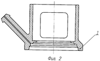
На фиг.2 - корпус вакуумного механизма. Figure 2 - the housing of the vacuum mechanism.
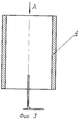
На фиг.3 - втулка с рабочей частью. Figure 3 - sleeve with a working part.
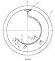
На фиг.4 - вид сверху втулки с рабочей частью. Figure 4 is a top view of the sleeve with the working part.
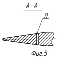
На фиг.5 - сечение А-А. Figure 5 is a section aa.
На фиг.6 - сечение Б-Б. Figure 6 is a section bB.
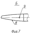
На фиг.7 - вид сверху на конец рабочей части. 7 is a top view of the end of the working part.
Инструмент содержит центрирующий вакуумный механизм, состоящий из корпуса 1 с кольцевой проточкой 2, штуцера 3, для подсоединения к источнику вакуума (не показан) и цилиндрической втулки 4, на которой посредством держателя 5 закреплена, например, с помощью "ласточкиного хвоста" съемная рабочая часть 6 с лезвием и канавкой 7 на ее наружной поверхности. На конце рабочей части, выполненной в виде плоского шпателя с заточкой 8 с наружной стороны, для продевания нити имеется отверстие 9, ось которого параллельна вертикальной оси инструмента. The tool contains a centering vacuum mechanism, consisting of a housing 1 with an
Инструмент используют следующим образом. На роговице отмечают центральную зону диаметром, равным внутреннему диаметру окружности будущего тоннеля. Производят, например, две радиальные насечки роговицы на 12-ти и на 6-ти часах заданной длины и глубины. Устанавливают вакуумный механизм на глазное яблоко, центрируют его относительно отмеченной центральной зоны и фиксируют в нужном положении путем подачи вакуума в кольцевую проточку 2. Окна, выполненные на верхней цилиндрической части вакуумного механизма, облегчают визуальный контроль за правильностью его установки и возможность работы с рабочей частью инструмента. Конец рабочей части 6 инструмента, с заправленной в отверстие 9 нитью, вставляют в насечку на 12-ти часах, при этом внутреннюю цилиндрическую поверхность корпуса 1 используют как направляющую для цилиндрической вставки 4 с рабочей частью 6. При помощи вращательного движения производят циркулярное расслаивание роговицы до насечки на 6-ти часах и из его отверстия удаляют нить, а инструмент обратным движением выводят из тоннеля. Таким образом сформирована одна половина тоннеля и в него проведена нить для введения биосовместимого материала. Вторая половина тоннеля формируется аналогичным образом от насечки на 6-ти часах до насечки на 12-ти часах. Таким образом тоннель полностью готов и в него с помощью нитей вводится биосовместимый материал в виде двух полуколец. The tool is used as follows. On the cornea note the central zone with a diameter equal to the inner diameter of the circumference of the future tunnel. For example, two radial corneal incisions are produced at 12 and 6 hours of a given length and depth. Install the vacuum mechanism on the eyeball, center it relative to the marked central zone and fix it in the desired position by applying vacuum to the
Применение данного инструмента за счет использования опорной поверхности, площадь которой значительно больше, чем площадь вакуумной проточки, использования направляющей при выполнении тоннеля в роговице и одновременного с формированием тоннеля проведения в него нити для последующего ввода биосовместимого материала значительно снижает травматизацию роговицы и позволяет более точно скоррегировать миопию. The use of this tool through the use of a supporting surface, the area of which is significantly larger than the area of the vacuum groove, the use of a guide when performing a tunnel in the cornea and simultaneously with the formation of a tunnel holding a thread for subsequent insertion of biocompatible material significantly reduces corneal trauma and allows more accurate myopia .
Claims (6)
Priority Applications (1)
| Application Number | Priority Date | Filing Date | Title |
|---|---|---|---|
| RU2000126936/14A RU2217110C2 (en) | 2000-10-27 | 2000-10-27 | Instrument for exfoliation of cornea |
Applications Claiming Priority (1)
| Application Number | Priority Date | Filing Date | Title |
|---|---|---|---|
| RU2000126936/14A RU2217110C2 (en) | 2000-10-27 | 2000-10-27 | Instrument for exfoliation of cornea |
Publications (2)
| Publication Number | Publication Date |
|---|---|
| RU2000126936A RU2000126936A (en) | 2002-09-10 |
| RU2217110C2 true RU2217110C2 (en) | 2003-11-27 |
Family
ID=32026432
Family Applications (1)
| Application Number | Title | Priority Date | Filing Date |
|---|---|---|---|
| RU2000126936/14A RU2217110C2 (en) | 2000-10-27 | 2000-10-27 | Instrument for exfoliation of cornea |
Country Status (1)
| Country | Link |
|---|---|
| RU (1) | RU2217110C2 (en) |
Cited By (2)
| Publication number | Priority date | Publication date | Assignee | Title |
|---|---|---|---|---|
| RU172667U1 (en) * | 2017-01-12 | 2017-07-18 | Федеральное государственное автономное учреждение "Межотраслевой научно-технический комплекс "Микрохирургия глаза" имени академика С.Н. Федорова" Министерства здравоохранения Российской Федерации | Microsurgical instrument for raising the corneal flap during repeated LASIK surgery in patients after radial keratotomy |
| CN109498263A (en) * | 2018-12-05 | 2019-03-22 | 西安市第医院 | A kind of lamellar cornea stripper |
Citations (3)
| Publication number | Priority date | Publication date | Assignee | Title |
|---|---|---|---|---|
| US4526171A (en) * | 1980-01-15 | 1985-07-02 | Schachar Ronald A | Cornea incision device |
| US4619259A (en) * | 1980-05-09 | 1986-10-28 | Graybill Walter R | Ophthalmic surgery tool |
| US5846256A (en) * | 1994-01-07 | 1998-12-08 | Keravision, Inc. | Device and method for inserting a biocompatible material into the corneal stroma |
-
2000
- 2000-10-27 RU RU2000126936/14A patent/RU2217110C2/en not_active IP Right Cessation
Patent Citations (3)
| Publication number | Priority date | Publication date | Assignee | Title |
|---|---|---|---|---|
| US4526171A (en) * | 1980-01-15 | 1985-07-02 | Schachar Ronald A | Cornea incision device |
| US4619259A (en) * | 1980-05-09 | 1986-10-28 | Graybill Walter R | Ophthalmic surgery tool |
| US5846256A (en) * | 1994-01-07 | 1998-12-08 | Keravision, Inc. | Device and method for inserting a biocompatible material into the corneal stroma |
Cited By (3)
| Publication number | Priority date | Publication date | Assignee | Title |
|---|---|---|---|---|
| RU172667U1 (en) * | 2017-01-12 | 2017-07-18 | Федеральное государственное автономное учреждение "Межотраслевой научно-технический комплекс "Микрохирургия глаза" имени академика С.Н. Федорова" Министерства здравоохранения Российской Федерации | Microsurgical instrument for raising the corneal flap during repeated LASIK surgery in patients after radial keratotomy |
| CN109498263A (en) * | 2018-12-05 | 2019-03-22 | 西安市第医院 | A kind of lamellar cornea stripper |
| CN109498263B (en) * | 2018-12-05 | 2024-05-24 | 西安市第一医院 | Lamellar corneal peeling device |
Similar Documents
| Publication | Publication Date | Title |
|---|---|---|
| US4688570A (en) | Ophthalmologic surgical instrument | |
| US4796623A (en) | Corneal vacuum trephine system | |
| EP0442156A1 (en) | Automatic corneal shaper | |
| US7922735B2 (en) | Device for cutting the cornea of an eye | |
| US5342378A (en) | Sectioning device for lamellar surgery | |
| US5486188A (en) | Keratoscopic surgical instrument for making radial and arcuate corneal incisions | |
| US6143010A (en) | Corneal vacuum centering device | |
| US4423728A (en) | Cam-guided trephine | |
| US5766198A (en) | Surgical knife employing a vacuum to ensure precise depth of incisions | |
| US5569280A (en) | Ophthalmic template | |
| US10779990B2 (en) | Ophthalmic incisional procedure instrument and method | |
| US5192293A (en) | Drill guide for orbital implant | |
| US4844060A (en) | Fixation ring for radial keratotomy | |
| US4763651A (en) | Trephine and method | |
| US5645554A (en) | Trephinator for treating subungual hematomas | |
| US5618292A (en) | Corneal drape or template for performing a radial-keratotomy procedure | |
| US4357941A (en) | Instrument for marking out the central optical zone of the cornea | |
| RU2217110C2 (en) | Instrument for exfoliation of cornea | |
| US5226905A (en) | Instrument for surgery of the cornea | |
| WO2019095593A1 (en) | Variable-diameter acetabulum file | |
| Waring et al. | The Hanna suction punch block and trephine system for penetrating keratoplasty | |
| CA1185860A (en) | Ophthalmologic surgical instrument | |
| CN115120406B (en) | Eye axial marker | |
| EP0959832A2 (en) | Opthamological instruments and methods of use | |
| RU2093124C1 (en) | Device to mark cornea at making corneal cuts |
Legal Events
| Date | Code | Title | Description |
|---|---|---|---|
| MM4A | The patent is invalid due to non-payment of fees |
Effective date: 20041028 |