RU2217503C2 - Method and installation for melting mineral materials - Google Patents
Method and installation for melting mineral materials Download PDFInfo
- Publication number
- RU2217503C2 RU2217503C2 RU2002101914/02A RU2002101914A RU2217503C2 RU 2217503 C2 RU2217503 C2 RU 2217503C2 RU 2002101914/02 A RU2002101914/02 A RU 2002101914/02A RU 2002101914 A RU2002101914 A RU 2002101914A RU 2217503 C2 RU2217503 C2 RU 2217503C2
- Authority
- RU
- Russia
- Prior art keywords
- charge
- gases
- melting
- sections
- materials
- Prior art date
Links
Images

Landscapes
- Manufacture And Refinement Of Metals (AREA)
Abstract
Description
Область техники
Изобретение относится и различным областям промышленности для производства материалов из расплавов и может быть использовано для восстановительной плавки руд и концентратов в металлургии, в фосфорной и других отраслях промышленности, а также для плавки материалов в нейтральной и окислительной среде в ванных стекловаренных и других печах в промышленности строительных материалов.Technical field
The invention relates to various industries for the production of materials from melts and can be used for reductive smelting of ores and concentrates in metallurgy, phosphoric and other industries, as well as for smelting materials in a neutral and oxidizing environment in glass melting bathtubs and other furnaces in the building industry materials.
Предшествующий уровень техники
Известен способ производства фосфора восстановительной плавкой шихты из фосфоритов и кварцитов в рудно-термической печи. Фосфориты предварительно обжигают в шахтных печах, затем выделяют фракцию 5-50 мм, смешивают ее с кварцитом и коксом в расчетном количестве и подают в рудно-термическую печь, где возгоняют фосфор, а шлаки и феррофосфор сливают через летки (В.А. Ершов, В. Н. Белов. Технология фосфора, Л., "Химия", Ленинградское отделение, 1979, с. 120-129, 222-228).State of the art
A known method of producing phosphorus reducing smelting mixture from phosphorites and quartzites in an ore-thermal furnace. Phosphorites are preliminarily fired in shaft furnaces, then a fraction of 5-50 mm is isolated, mixed with quartzite and coke in the calculated amount and fed to the ore-thermal furnace, where phosphorus is sublimated, and slag and ferrophosphorus are poured through notches (V.A. Ershov, V. N. Belov. Technology of phosphorus, L., "Chemistry", Leningrad Branch, 1979, pp. 120-129, 222-228).
К недостаткам данного способа и рудно-термической печи для плавки шихты является потеря мелкофракционного сырья (менее 5 мм), низкая площадь фильтрации газов в слое шихты перед ее плавкой, сдерживающая рост агрегатной производительности, и применение двухкратного обжига компонентов шихты в отдельных обжиговых и плавильных печах. The disadvantages of this method and the ore-thermal furnace for melting the charge are the loss of finely-fractioned raw materials (less than 5 mm), the low gas filtration area in the charge layer before its melting, which restrains the growth of aggregate productivity, and the use of double-firing of the charge components in separate kiln and melting furnaces .
Наиболее близким по технической сущности и достигаемому результату является способ восстановительной плавки железных руд или окускованных железорудных концентратов. Способ включает приготовление и подачу шихты в зону обжига, сжигание и противоточную фильтрацию газов в слое шихты, вывод плава и шлаков. Доменная печь для реализации данного способа содержит шахту с расположенным под ней горном, фурмы, устройство для подачи в шахту шихты, летки чугуна и шлака, систему газоочистки (Большая советская энциклопедия, М., Изд-во "Советская энциклопедия", 1972, т.8, с. 423-426). The closest in technical essence and the achieved result is a method of reducing smelting of iron ores or agglomerated iron ore concentrates. The method includes preparing and feeding the charge into the firing zone, burning and countercurrent filtering of gases in the charge layer, withdrawal of melt and slag. A blast furnace for the implementation of this method contains a mine with a mine located below it, lances, a device for feeding burden to the mine, cast iron and slag tap holes, and a gas purification system (Great Soviet Encyclopedia, Moscow, Sovetskaya Encyclopedia Publishing House, 1972, vol. 8, p. 423-426).
Недостатками данного способа и доменной печи являются низкая площадь фильтрации в слое газов и большая высота шихты, повышающая гидравлическое сопротивление и энергозатраты с дутьем и сдерживающая рост производительности; двухкратный обжиг шихты в процессе плавки и до плавки с применением удорожающей постели при обжиге окатышей и производстве агломерата; сложность и громоздкость агломерационных и обжиговых машин; узкая фракция окатышей, снижающая производительность грануляторов; громадный расход дорогостоящего кокса; высокая запыленность отходящих газов и громоздкая система их очистки. The disadvantages of this method and blast furnace are low filtration area in the gas layer and a large charge height, which increases hydraulic resistance and energy consumption with blast and inhibits productivity growth; two-time firing of the mixture in the melting process and before melting with the use of a more expensive bed when firing pellets and the production of sinter; complexity and cumbersome sintering and roasting machines; a narrow fraction of pellets, which reduces the productivity of granulators; huge consumption of expensive coke; high dust content of exhaust gases and a bulky system for cleaning them.
Общими недостатками этого и подобного способов и установок для их реализации является низкая производительность зоны обжига перед плавкой шихты, громоздкость и дороговизна обжиговых машин, используемых в шихтопроизводстве, применение и высокий расход дефицитного и дорогостоящего кокса в процессе восстановительной плавки, громоздкость и сложность основного оборудования и системы газоочистки, высокие затраты электроэнергии и топлива на производство продукта. Common disadvantages of this and similar methods and installations for their implementation are the low productivity of the firing zone before melting the charge, the bulkiness and high cost of the firing machines used in charge production, the use and high consumption of scarce and expensive coke in the recovery smelting process, the bulkiness and complexity of the main equipment and system gas purification, high costs of electricity and fuel for the production of the product.
В силу указанных недостатков, присущих перечисленным способам, дальнейшая интенсификация процесса плавки минеральных материалов и снижение капитальных и эксплуатационных затрат становятся затруднительными, а для ряда материалов невозможными. Due to these drawbacks inherent in the above methods, further intensification of the process of smelting mineral materials and lower capital and operating costs become difficult, and for some materials impossible.
Раскрытие изобретения
В основу изобретения положена задача усовершенствования способа плавки минеральных материалов путем увеличения площади фильтрации в слое газов перед плавкой и обеспечения скоростного нагрева шихты, осуществления частичной или полной замены кокса каменным углем при восстановительной плавке минеральных материалов, повышения компактности и снижения материалоемкости оборудования, снижения электроэнергии и теплозатрат.Disclosure of Invention
The basis of the invention is the task of improving the method of smelting mineral materials by increasing the filtration area in the gas layer before smelting and providing high-speed heating of the charge, partially or completely replacing coke with coal during smelting of mineral materials, increasing the compactness and reducing the material consumption of equipment, reducing energy and heat consumption .
Поставленная задача решается тем, что способ скоростной плавки минеральных материалов включает приготовление и подачу шихты вертикально ориентированными слоями в зону обжига, сжигание и перекрестную фильтрацию газов в слое шихты, вывод плава и шлаков, при этом шихту подают параллельными слоями, причем на плавку подают шихту фракции 3-25 мм, а в состав шихты вводят каменный уголь в качестве восстановителя. The problem is solved in that the method of high-speed smelting of mineral materials involves the preparation and supply of a charge with vertically oriented layers to the firing zone, burning and cross-filtering gases in the charge layer, the output of melt and slag, while the charge is fed in parallel layers, and the fraction is charged to the smelting 3-25 mm, and coal is introduced into the mixture as a reducing agent.
Поставленная задача решается тем, что установка содержит бункер для шихты, шахту с расположенным под ней горном фурмы, летки для слива сплава и шлака, воздуховод, газоходы для отходящих газов. При этом шахта выполнена прямоугольного сечения и разделена на секции для шихты, газов из воздуховода и отходящих газов, ограниченные вертикальными колосниковыми решетками, закрепленными в продольных стенках, при этом сверху на секциях газов из воздуховода установлены перекрытия, а на секциях для отходящих газов перекрытия установлены сверху и снизу. The problem is solved in that the installation contains a bunker for the charge, a shaft with a lance mountain located beneath it, tap holes for draining the alloy and slag, an air duct, and ducts for exhaust gases. In this case, the mine is made in a rectangular section and is divided into sections for the charge, gases from the duct and exhaust gases, limited by vertical grate grids fixed in the longitudinal walls, with overlapping sections installed on the gas sections from the duct above and overlapping sections on the sections for exhaust gases and from below.
Возможен вариант, когда в воздуховод введены горелки. A variant is possible when burners are introduced into the duct.
Такое выполнение способа позволяет перед плавлением интенсивно нагревать шихту до температуры плавления с многократным увеличении производительности; снижать или полностью заменять кокс в шихте на каменный уголь; многократно снижать ширину (толщину) фильтрующего слоя, расширив при этом зерновой состав шихты с увеличением ее удельной поверхности, и обеспечивать практически полное пылеподавление слоем самой шихты. This embodiment of the method allows before melting to intensively heat the mixture to a melting temperature with a multiple increase in productivity; reduce or completely replace coke in the mixture with coal; repeatedly reduce the width (thickness) of the filter layer, while expanding the grain composition of the mixture with an increase in its specific surface, and provide almost complete dust suppression by the layer of the mixture itself.
Конструктивные особенности изобретения позволяют многократно увеличивать площадь фильтрации (площадь колосниковых решеток) в слое газов и повышать производительность при уменьшении высоты и полезного объема шихты, рационально распределять в слое газы и снижать гидравлическое сопротивление слоя шихты, оперативно вводить установку в режим, производить спекание шихты в шахте, исключив при этом систему предварительного обжига материалов, обеспечивая компактность производства и высокую экономическую эффективность. Design features of the invention allow to increase the filtration area (grate area) in the gas layer many times and increase productivity while reducing the height and useful volume of the charge, efficiently distribute gases in the layer and reduce the hydraulic resistance of the charge layer, quickly put the unit into operation, and sinter the mixture in the mine while eliminating the system of preliminary firing of materials, ensuring compact production and high economic efficiency.
Сущность способа скоростной плавки минеральных материалов заключается в организованной фильтрации газов в слое шихты, которая обеспечивается переходом от противоточной фильтрации газов в нисходящем слое к перекрестноточной фильтрации газов. Это позволяет разделить один поток материала и один поток фильтрующихся в слое газов на множество потоков, а снижение толщины фильтрующих слоев многократно снижает нагрузку на зерна обжигаемой шихты, что обеспечивает высокую сопротивляемость их разрушению и возможность подачи шихты без обособленной предварительной термообработки. The essence of the method of high-speed melting of mineral materials is organized gas filtration in the charge layer, which is provided by the transition from countercurrent gas filtration in the downstream layer to cross-flow gas filtration. This allows you to separate one stream of material and one stream of gases filtered in the layer into many flows, and a decrease in the thickness of the filter layers greatly reduces the load on the grains of the calcined charge, which provides high resistance to their destruction and the possibility of feeding the mixture without separate preliminary heat treatment.
Деление шихты на параллельные вертикально ориентированные потоки обеспечивает высокую проходимость материала через зону обжига в зону плавки и в сочетании с перекрестноточной фильтрацией и сжиганием в слое газов создаются благоприятные условия для снижения размера зерен шихты до 3 мм и скоростного их нагрева без увеличения сопротивления слоя при многократном увеличении производительности. Dividing the charge into parallel vertically oriented flows provides a high throughput of the material through the firing zone to the melting zone and in combination with cross-flow filtration and burning in the gas layer, favorable conditions are created for reducing the grain size of the mixture to 3 mm and heating them quickly without increasing the layer resistance with a multiple increase performance.
Применение шихты с размером зерен менее 3 мм нерационально, поскольку ухудшается проходимость шихты в зоне обжига в ее конечной части при температуре размягчения материала и появления жидкой фазы, а увеличение размера зерен шихты выше 25 мм нерационально, т.к. увеличивается ширина потоков (слоев) материала и снижается площадь фильтрации в слое газов. The use of a charge with a grain size of less than 3 mm is irrational, since the passability of the charge in the firing zone in its final part is deteriorated at the softening temperature of the material and the appearance of the liquid phase, and an increase in the size of the grain of the charge above 25 mm is irrational, because the width of the flows (layers) of the material increases and the filtration area in the gas layer decreases.
Скоростной нагрев шихты в зоне обжига создает предпосылки для замены кокса каменным углем, который в зоне обжига газифицирует и освобождается от летучих компонентов, а коксовый остаток с шихтой поступает по назначению в зону плавления. Частичная или полная замена кокса на каменный уголь существенно повышает экономический потенциал производства. Rapid heating of the charge in the firing zone creates the prerequisites for replacing coke with coal, which in the firing zone is gasified and freed of volatile components, and the coke residue with the charge enters the melting zone as intended. Partial or complete replacement of coke with coal significantly increases the economic potential of production.
Выполнение шахты прямоугольного сечения позволяет устанавливать в ней газораспределительные стенки (колосниковые решетки) в унифицированном варианте, что упрощает конструкцию, ускоряет монтажные и ремонтные работы и стабилизирует газодинамику и равномерный нагрев шихты по всей высоте шахты. The implementation of the rectangular mine allows you to install gas distribution walls (grate) in it in a unified version, which simplifies the design, accelerates installation and repair work and stabilizes gas dynamics and uniform heating of the charge over the entire height of the mine.
Деление шахты колосниковыми решетками на секции позволяет формировать равные по ширине нисходящие слои шихты и увеличивать в десятки раз площадь фильтрации в слое газов и соответственно этому повышать производительность зоны обжига и установки в целом. The division of the mine with grate grates into sections allows the formation of equal-in-depth descending layers of the charge and increases tens of times the filtration area in the gas layer and, accordingly, to increase the productivity of the firing zone and the installation as a whole.
Применение неподвижных колосниковых решеток, закрепленных в продольных стенках шахты, позволяет изготавливать решетки из жаростойких неметаллических материалов, обеспечивая им высокую эксплуатационную надежность при работе в высокотемпературной и агрессивной газовой среде. Вертикальное размещение колосниковых решеток обеспечивает им высокое (50-60%) живое сечение. Это снижает материалоемкость колосниковых решеток и обеспечивает снижение энергозатрат с газами и дутьевым воздухом и способствует увеличению газопроницаемости и производительности. The use of fixed grates, fixed in the longitudinal walls of the shaft, allows the manufacture of gratings from heat-resistant non-metallic materials, providing them with high operational reliability when working in high-temperature and aggressive gas environments. The vertical placement of grate grids provides them with a high (50-60%) live section. This reduces the material consumption of the grate and provides a reduction in energy consumption with gases and blast air and contributes to an increase in gas permeability and productivity.
Установка бункера шихты над колосниковыми решетками позволяет исключить выбросы дымовых газов, а перекрытия вместе с парами колосниковых решеток смежных секций создают полости, необходимые для подачи в каждый слой газовоздушной смеси и вывода из каждого слоя отходящих газов. The installation of the bunker of the charge over the grate allows to eliminate flue gas emissions, and overlapping together with the pairs of grate grates of adjacent sections create the cavities necessary for supplying to each layer of the gas-air mixture and the output of each layer of exhaust gases.
Подключение полостей поочередно к подаче газовоздушной смеси и отводу отходящих газов обеспечивает фильтрующий перекрестноточный режим в каждом нисходящем слое. Connecting the cavities alternately to the supply of the gas-air mixture and the removal of exhaust gases provides a filter cross-flow mode in each descending layer.
Сообщение вводных полостей с воздуховодом с двух его противоположных сторон позволяет увеличить производительность зоны обжига в два раза без применения дополнительных газоходов, а оснащение выводных полостей снизу перекрытиями предотвращает утечку газов из зоны плавки (горна) без их теплоиспользования в слое шихты. The communication of the input cavities with the duct from its two opposite sides allows to double the productivity of the firing zone without the use of additional flues, and equipping the outlet cavities from below with ceilings prevents the leakage of gases from the melting zone (hearth) without heat use in the charge layer.
Применение горелок в воздуховоде необходимо для запуска печи при восстановительной плавке и для постоянного сжигания горючего при нейтральной или окислительной плавке шихты. The use of burners in the duct is necessary to start the furnace during reduction smelting and for continuous combustion of fuel during neutral or oxidative smelting of the charge.
Применение воздуховода необходимо для создания высокотемпературного теплоносителя при сжигании газов, поступающих из горна и горелок. Этот теплоноситель затем используется для нагрева, декарбонизации и спекания шихты, поступающей без охлаждения в зону плавки. The use of an air duct is necessary to create a high-temperature coolant when burning gases coming from a hearth and burners. This coolant is then used to heat, decarbonize, and sinter the mixture, which enters the melting zone without cooling.
Достоинствами способа скоростной плавки минеральных материалов и установки для его осуществления является высокая производительность, возможность использования дешевых восстановителей, компактность, низкая материалоемкость, высокая экологическая безопасность (пылевынос менее 0,1% без применения пылеочистных устройств). The advantages of the method of high-speed melting of mineral materials and the installation for its implementation are high productivity, the ability to use cheap reducing agents, compactness, low material consumption, high environmental safety (dust removal of less than 0.1% without the use of dust cleaning devices).
Ниже описаны конкретные примеры реализации предложенного способа посредством установки для скоростной плавки минеральных материалов. The following are specific examples of the implementation of the proposed method through the installation for high-speed smelting of mineral materials.
Краткое описание чертежей
В дальнейшем изобретение поясняется конкретными вариантами его выполнения со ссылками на прилагаемые чертежи, на которых:
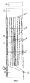
фиг.1 изображает установку для скоростной плавки минеральных материалов, согласно изобретению, в поперечном разрезе;
фиг.2 - разрез I-I на фиг.1;
фиг.3 - разрез II-II на фиг.1.Brief Description of the Drawings
The invention is further explained by specific options for its implementation with reference to the accompanying drawings, in which:
figure 1 depicts an installation for high-speed melting of mineral materials, according to the invention, in cross section;
figure 2 is a section II in figure 1;
figure 3 - section II-II in figure 1.
Установка для скоростной плавки минеральных материалов включает шахту 1 прямоугольного сечения, с расположенным под ней горном 2, фурмы 3, ленточный конвейер подачи шихты 4, летки 5 для слива плава и летки 6 для слива шлака, систему газоочистки 7. В установке шахта 1 по высоте разделена на секции колосниковыми решетками 8, закрепленными в продольных стенках 9, и сверху колосниковые решетки 8 введены в бункер шихты 10, а снизу опущены в горн 2, причем в бункере 10 между колосниковыми решетками 8 смежных секций выполнены перекрытия 11, образующие с колосниковыми решетками 8 и продольными стенками 9 вводные 12 и выводные 13 полости, которые поочередно соединены через окна 14 в продольных стенках 9 и воздуховод 15 с горном 2 и газоходами 16 отходящих газов. The installation for high-speed melting of mineral materials includes a
В установке вводные полости 12 соединены с воздуховодом 15 с двух противоположных его сторон, а выводные полости 13 оснащены перекрытиями 17. В воздуховод 15 введены горелки 18. In the installation, the
Способ осуществляют и установка для скоростной плавки минеральных материалов работает следующим образом. The method is carried out and the installation for high-speed melting of mineral materials works as follows.
Шихту фракции 3-25 мм надлежащего химического и минералогического состава, предварительно обожженную или необожженную, или частично обожженную в виде зерен, щебня или гранул подают по ленточному конвейеру 4 в бункер 10, из которого она распределяется по щелевым каналам 19, образованным колосниковыми решетками 8 и продольными стенками 9. В щелевых каналах 19 шихта образует вертикально ориентированные параллельные слои, которые опускаются вниз за счет гравитации по мере слива плава и шлака через летки 5 и 6. The charge fraction 3-25 mm of the proper chemical and mineralogical composition, pre-burned or unburnt, or partially burnt in the form of grains, gravel or granules is fed through a
В горн 2 через фурмы 3 подают воздух и часть жидкого или газообразного горючего. Основную часть горючего сжигают в воздуховоде 15, вводных полостях 12 и в щелевых каналах 19 в слое (в каждом слое) шихты. При восстановительной плавке шихту готовят в смеси с известняком, каменным углем или с коксом и каменным углем, и часть углевода (коксовый остаток при вводе в шихту каменного угля) расходуется на восстановительные процессы, а летучие компоненты угля сгорают в потоке воздуха в зоне обжига. Газы из горна 2 поднимаются вверх и поступают в вводные полости 12 снизу и через воздуховод 15 и окна 14, а при окислительной (нейтральной) плавке газы из горна смешиваются с воздухом, поступающим по стрелке 20, и с газами, поступающими через горелки 18, сгорают в воздуховоде 15 и через окна 14 дымовые газы по стрелкам 21 поступают в вводные полости 12. Затем газы поворачивают на 90o и по стрелкам 22 через щели в колосниковых решетках 8 поступают в нисходящие слои (потоки) шихты, фильтруются в них по стрелкам 23 в перекрестном токе.In the hearth 2 through the tuyeres 3 serves air and part of the liquid or gaseous fuel. The main part of the fuel is burned in the
Отработанные (отходящие) газы через щели в колосниковых решетках 8 с противоположных сторон каждого слоя вытекают в выводные полости 13, поворачивают в них на 90o по стрелкам 24 и через окна 14 вытекают по стрелкам 25 в газоходы отходящих газов 16 и по газоходу 26 поступают в систему газоочистки 7, откуда очищенные газы по стрелке 27 следуют на дальнейшее теплоиспользование или на выброс. Вследствие низких скоростей газов в шихте и высокой пылеулавливающей способности слоя очистка отходящих газов практически упраздняется.Exhaust (exhaust) gases through slots in the
Лучший вариант осуществления изобретения
Готовят шихту из сырых материалов, включая известняк. Шихту гранулируют с получением фракции 5-25 мм. Каменный уголь в виде штыба фракции 3-6 мм вводят в шихту после ее сушки. Пересчет дозировки в шихту каменного угля производят по содержанию в угле кокса (за вычетом летучих компонентов). Шихту сушат в отдельно взятой сушилке с фильтрацией теплоносителя в слое одновременно в прямоточном, противоточном и перекрестноточном направлениях. Это позволяет практически без разрушений гранул осуществить скоростную сушку шихты до остаточной влажности 1-2% при паросъеме 600-800 кг/м3•ч, и для сушки, например, 1000 т/ч гранул необходима сушилка объемом около 150 м3. В качестве горючего для сушки гранул используют полугаз, следующий от восстановительной плавки шихты. Слоевая секционная сушилка по данной технологии не требует пылеочистки отходящих газов, поскольку сам слой гранул является мокрым зернистым фильтром.The best embodiment of the invention
A mixture is prepared from raw materials, including limestone. The mixture is granulated to obtain a fraction of 5-25 mm. Coal in the form of a bayonet fraction 3-6 mm is introduced into the charge after drying. Recalculation of the dosage into the mixture of coal is carried out according to the content of coke in the coal (minus the volatile components). The mixture is dried in a separate dryer with filtration of the coolant in the layer at the same time in direct-flow, counter-current and cross-flow directions. This allows for virtually no destruction of the granules to carry out high-speed drying of the mixture to a residual moisture content of 1-2% with steam removal of 600-800 kg / m 3 • h, and for drying, for example, 1000 t / h of granules, a dryer with a volume of about 150 m 3 is needed. As a fuel for drying the granules, a half-gas is used, which follows from the reduction smelting of the charge. The layered sectional dryer according to this technology does not require dust cleaning of the exhaust gases, since the granule layer itself is a wet granular filter.
Шихту обжигают и плавят в вышеуказанной установке, в которой для суточной плавки 10 тыс. т шихты создают полезный объем шахты равным 400-600 м3, при этом снижают в 5-6 раз высоту шахты по сравнению с традиционной доменной печью такой же мощности. Площадь перекрестноточной фильтрации газов в такой шахте составляет 700-1000 м2 и ее достаточно для спекания 1-1,5 тыс. т/ч высушенных гранул. В установке наличие бункера шихты, вводных и выводных полостей позволяет упростить систему загрузки шахты, исключив при этом колошниковое устройство, большой конус, приемную воронку, малый конус, распределитель шихты и воронку большого конуса. Время вывода установки для скоростной плавки минеральных материалов на регламентный режим составляет 5-6 ч.The mixture is fired and melted in the above installation, in which for
Для лучшего понимания существа изобретения рассмотрим конкретные примеры осуществления способа. For a better understanding of the invention we consider specific examples of the method.
Пример 1
Ванную печь для производства листового, тарного и других видов стекла укомплектовывают шахтой, как показано на фиг.1-3. Отходящие от ванны газы смешивают с воздухом и вместе с дымовыми газами от сжигания горючего горелками в воздуховоде подают в вводные полости. Шихту вместе с боем стекла загружают в бункер, а спекшийся материал разгружают в зоне плавки. Расход топлива на варку стекла снижается на 20-30%, а производительность ванной печи повышается в 1,5-2 раза.Example 1
The bathroom furnace for the production of sheet, container and other types of glass is equipped with a shaft, as shown in figures 1-3. The gases leaving the bath are mixed with air and, together with the flue gases from burning fuel by the burners in the duct, are fed into the inlet cavities. The charge, together with the glass break, is loaded into the bunker, and the sintered material is unloaded in the melting zone. Fuel consumption for glass melting is reduced by 20-30%, and the productivity of the bathroom furnace is increased by 1.5-2 times.
Пример 2
Готовят железорудные окатыши фракции 5-25 мм, сушат их до влажности 1-2% и смешивают с каменноугольным штыбом в соотношении : окатыши : каменноугольный штыб = 1: 0,6-0,7.Example 2
Iron ore pellets of a fraction of 5-25 mm are prepared, dried to a moisture content of 1-2% and mixed with a coal block in the ratio: pellets: coal block = 1: 0.6-0.7.
Горн доменной печи укомплектовывают шахтой прямоугольного сечения с вертикально расположенными колосниковыми решетками, полостями и перекрытиями, как показано на фиг.1-3. Газораспределительные стенки (колосниковые решетки) устанавливают из расчета выхода 1-1,5 т/м2•ч спеченного продукта при газопроницаемости 0,5-0,6 м/с. Высушенные окатыши с каменноугольным штыбом подают в бункер установки для скоростной плавки. Горн обслуживают по традиционной технологии. Производительность установки повышается в 3-4 раза при снижении полезного объема шахты в 5-6 раз. Одновременно с этим исключаются специальные производства по обжигу извести, окатышей и агломерации шихты, за счет чего существенно снижается расход горючего и электроэнергии на выплавку чугуна.The blast furnace hearth is equipped with a rectangular mine with vertically arranged grate, cavities and ceilings, as shown in FIGS. 1-3. Gas distribution walls (grates) are set based on the yield of 1-1.5 t / m 2 • h of sintered product with gas permeability of 0.5-0.6 m / s. Dried pellets with a coal mine serve in the hopper of the installation for high-speed melting. Horn served by traditional technology. The productivity of the installation increases by 3-4 times while reducing the useful volume of the mine by 5-6 times. At the same time, special production is excluded for calcining lime, pellets and sintering of the charge, thereby significantly reducing the consumption of fuel and electricity for smelting pig iron.
Само собой разумеется, что настоящее изобретение не ограничивается описанными и показанными здесь примерами его выполнения и что возможны различные модификации и другие варианты осуществления установки для скоростной плавки минеральных материалов без отклонения от объема и существа настоящего изобретения. It goes without saying that the present invention is not limited to the examples described and shown here, and that various modifications and other embodiments of the apparatus for the rapid melting of mineral materials are possible without deviating from the scope and essence of the present invention.
Промышленная применимость
На основе данного изобретения могут быть разработаны и изготовлены различные конструкции установок для скоростной плавки минеральных материалов. Такие установки предназначены для плавки различных минеральных материалов с целью получения чугуна, цветных металлов, стекла, фосфора и прочего.Industrial applicability
On the basis of this invention can be developed and manufactured various designs of plants for high-speed smelting of mineral materials. Such plants are designed for the smelting of various mineral materials in order to obtain cast iron, non-ferrous metals, glass, phosphorus and others.
Настоящая конструкция характеризуется высокой производительностью, низким расходом металла и огнеупоров, низкими тепловыми и энергетическими затратами, компактностью, простотой конструкции и высокой экологической безопасностью. This design is characterized by high performance, low consumption of metal and refractories, low heat and energy costs, compactness, simplicity of design and high environmental safety.
Claims (5)
Priority Applications (1)
| Application Number | Priority Date | Filing Date | Title |
|---|---|---|---|
| RU2002101914/02A RU2217503C2 (en) | 2002-01-28 | 2002-01-28 | Method and installation for melting mineral materials |
Applications Claiming Priority (1)
| Application Number | Priority Date | Filing Date | Title |
|---|---|---|---|
| RU2002101914/02A RU2217503C2 (en) | 2002-01-28 | 2002-01-28 | Method and installation for melting mineral materials |
Publications (2)
| Publication Number | Publication Date |
|---|---|
| RU2002101914A RU2002101914A (en) | 2003-08-10 |
| RU2217503C2 true RU2217503C2 (en) | 2003-11-27 |
Family
ID=32027307
Family Applications (1)
| Application Number | Title | Priority Date | Filing Date |
|---|---|---|---|
| RU2002101914/02A RU2217503C2 (en) | 2002-01-28 | 2002-01-28 | Method and installation for melting mineral materials |
Country Status (1)
| Country | Link |
|---|---|
| RU (1) | RU2217503C2 (en) |
Cited By (2)
| Publication number | Priority date | Publication date | Assignee | Title |
|---|---|---|---|---|
| RU2267726C1 (en) * | 2004-04-20 | 2006-01-10 | Государственное образовательное учреждение высшего профессионального образования "Уральский государственный технический университет-УПИ" | Shaft furnace |
| RU2505764C2 (en) * | 2012-04-26 | 2014-01-27 | Открытое акционерное общество "Восточный научно-исследовательский углехимический институт" (ОАО "ВУХИН") | Drying method of granular carbonaceous or mineral materials, and drying plant of granular carbonaceous or mineral materials (versions) |
Citations (4)
| Publication number | Priority date | Publication date | Assignee | Title |
|---|---|---|---|---|
| SU30155A1 (en) * | 1930-02-28 | 1933-04-30 | Генри Смит Виллиам | Device for reducing metal ores |
| SU417479A1 (en) * | 1972-05-22 | 1974-02-28 | ||
| SU281497A1 (en) * | 1969-02-23 | 1978-02-15 | Центральный Ордена Трудового Красного Знамени Научно-Исследовательский Институт Черной Металлургии Им. И.П.Бардина | Method of obtaining low-carbon sponge iron or iron powder |
| PL230001B1 (en) * | 2015-01-30 | 2018-09-28 | Sroka Ritau Jacek | Training glove |
-
2002
- 2002-01-28 RU RU2002101914/02A patent/RU2217503C2/en not_active IP Right Cessation
Patent Citations (4)
| Publication number | Priority date | Publication date | Assignee | Title |
|---|---|---|---|---|
| SU30155A1 (en) * | 1930-02-28 | 1933-04-30 | Генри Смит Виллиам | Device for reducing metal ores |
| SU281497A1 (en) * | 1969-02-23 | 1978-02-15 | Центральный Ордена Трудового Красного Знамени Научно-Исследовательский Институт Черной Металлургии Им. И.П.Бардина | Method of obtaining low-carbon sponge iron or iron powder |
| SU417479A1 (en) * | 1972-05-22 | 1974-02-28 | ||
| PL230001B1 (en) * | 2015-01-30 | 2018-09-28 | Sroka Ritau Jacek | Training glove |
Cited By (2)
| Publication number | Priority date | Publication date | Assignee | Title |
|---|---|---|---|---|
| RU2267726C1 (en) * | 2004-04-20 | 2006-01-10 | Государственное образовательное учреждение высшего профессионального образования "Уральский государственный технический университет-УПИ" | Shaft furnace |
| RU2505764C2 (en) * | 2012-04-26 | 2014-01-27 | Открытое акционерное общество "Восточный научно-исследовательский углехимический институт" (ОАО "ВУХИН") | Drying method of granular carbonaceous or mineral materials, and drying plant of granular carbonaceous or mineral materials (versions) |
Similar Documents
| Publication | Publication Date | Title |
|---|---|---|
| CN112105880B (en) | Production of oxy-fuel clinker with special oxygen addition | |
| CN101538631B (en) | Process and device for smelting ferronickel and nickel-containing molten iron by using lower-nickel materials | |
| CN106893867B (en) | A kind of method of the muffle shaft furnace processing dirt of feed powder containing zinc-iron recycling zinc | |
| PL160334B1 (en) | Melting furnace PL | |
| CN101575654B (en) | Process and device for preparing iron alloy containing nickel and nickel-chromium | |
| CN101538632A (en) | Preparation process and device of sponge iron | |
| CN101203619A (en) | Method of operation of iron oxide recovery furnace for energy saving, volatile metals removal and slag control | |
| CN102409124A (en) | Continuous iron-making device by smelting reduction | |
| RU2690251C2 (en) | Metallurgical furnace for production of metal alloys | |
| CN109306407B (en) | Device and method for treating and utilizing metallurgical zinc-containing dust | |
| EP0122768A2 (en) | An electric arc fired cupola for remelting of metal chips | |
| PL125529B1 (en) | Apparatus for burning limestone and similar minerals in countercurrent regeneration type shaft furnace using dustyand/or fine-grained solid fuels | |
| CN103436703A (en) | Total-oxygen side-blown reduction smelting converter | |
| SU528040A3 (en) | The method of obtaining sponge iron from a mixture containing oxidized ores | |
| SK2792001A3 (en) | Method for heat-treating recyclings containing oil and iron oxide | |
| CN102146490B (en) | Reduction iron making method and device | |
| CN101749931A (en) | Smelting furnace | |
| RU2678557C2 (en) | Metallurgical furnace | |
| RU2217503C2 (en) | Method and installation for melting mineral materials | |
| SK2022001A3 (en) | Method for the thermal processing of residues containing heavy metals and iron oxide | |
| RU2299244C2 (en) | Modular furnace | |
| CN102618684A (en) | Continuous melting reduction iron-making device | |
| RU2079079C1 (en) | Method and shaft furnace for roasting of lump materials | |
| CN106191364A (en) | A kind of system and method utilizing wet piece of lateritic nickel ore direct-reduction to produce granulated iron | |
| WO2016148555A1 (en) | Method for the reduction smelting of steel and apparatus for carrying out said method |
Legal Events
| Date | Code | Title | Description |
|---|---|---|---|
| MM4A | The patent is invalid due to non-payment of fees |
Effective date: 20050129 |