RU2247227C2 - Jet end piece for hydraulic sand jet perforator - Google Patents
Jet end piece for hydraulic sand jet perforator Download PDFInfo
- Publication number
- RU2247227C2 RU2247227C2 RU2000114867/03A RU2000114867A RU2247227C2 RU 2247227 C2 RU2247227 C2 RU 2247227C2 RU 2000114867/03 A RU2000114867/03 A RU 2000114867/03A RU 2000114867 A RU2000114867 A RU 2000114867A RU 2247227 C2 RU2247227 C2 RU 2247227C2
- Authority
- RU
- Russia
- Prior art keywords
- jet
- channel
- end piece
- perforator
- section
- Prior art date
Links
- 239000004576 sand Substances 0.000 title 1
- 238000005488 sandblasting Methods 0.000 claims description 4
- 230000003247 decreasing effect Effects 0.000 abstract 1
- 230000000694 effects Effects 0.000 abstract 1
- 239000000126 substance Substances 0.000 abstract 1
- 230000015572 biosynthetic process Effects 0.000 description 4
- 230000006378 damage Effects 0.000 description 4
- 238000005755 formation reaction Methods 0.000 description 4
- 239000011435 rock Substances 0.000 description 3
- 238000001914 filtration Methods 0.000 description 2
- 238000002386 leaching Methods 0.000 description 2
- 238000004519 manufacturing process Methods 0.000 description 2
- 230000000149 penetrating effect Effects 0.000 description 2
- 230000002378 acidificating effect Effects 0.000 description 1
- 230000008030 elimination Effects 0.000 description 1
- 238000003379 elimination reaction Methods 0.000 description 1
- 239000000706 filtrate Substances 0.000 description 1
- 239000012530 fluid Substances 0.000 description 1
- 239000007788 liquid Substances 0.000 description 1
- 238000000034 method Methods 0.000 description 1
- 230000035515 penetration Effects 0.000 description 1
- 230000007704 transition Effects 0.000 description 1
- 238000011282 treatment Methods 0.000 description 1
Images
Landscapes
- Earth Drilling (AREA)
Abstract
Description
Изобретение относится к нефтегазодобывающей промышленности, а именно к насадкам для перфораторов с использованием струи направляемого действия, и может быть использовано в технике вскрытия продуктивных пластов для создания каналов и локальных щелей в скважинах с открытым забоем и обсаженных эксплуатационными колоннами, а также для вырезки обсадных колонн, расширения забоев в необсаженных скважинах и при струйно-направленных кислотных и других обработках забойных зон с целью интенсификации нефтегазодобычи.The invention relates to the oil and gas industry, in particular to nozzles for perforators using guided action jets, and can be used in the technique of opening productive formations to create channels and local gaps in open-hole wells and cased with production cores, as well as for cutting casing strings, expansion of faces in open-hole wells and with jet-directed acidic and other treatments of bottom-hole zones in order to intensify oil and gas production.
Известна конструкция насадки перфоратора, содержащая корпус, выполненный с каналами для подвода жидкости, цилиндр с сопловым каналом, тангенциально наклоненный относительно оси насадки. Цилиндр дополнительно содержит кольцевой канал, гидравлически связанный с каналом подвода жидкости и сопловым каналом [1]. Однако известная конструкция не позволяет достигать значительного повышения эффективности вскрытия пластов.A known design of the nozzle of a perforator containing a housing made with channels for supplying fluid, a cylinder with a nozzle channel, tangentially inclined relative to the axis of the nozzle. The cylinder further comprises an annular channel hydraulically connected to the liquid supply channel and the nozzle channel [1]. However, the known design does not allow to achieve a significant increase in the efficiency of the formation.
Наиболее близким к предлагаемому по технической сущности является насадка гидропескоструйного перфоратора для вскрытия нефтяных и газовых скважин, содержащая корпус и проточный коноидальный канал переменного сечения, выполненный щелевидным с отношением ширины щели к ее длине от 1/3 до 1/5, причем с уменьшением площади сечения выходного отверстия по отношению к входному [2]. Однако и эта насадка не позволяет значительно увеличить эффективность вскрытия продуктивных пластов.Closest to the proposed technical essence is the nozzle of a sandblasting drill for opening oil and gas wells, comprising a body and a flowing conoidal channel of variable cross section, made slit-like with a ratio of the width of the slit to its length from 1/3 to 1/5, with a decrease in the cross-sectional area the outlet in relation to the inlet [2]. However, this nozzle does not significantly increase the efficiency of opening productive formations.
Задачей настоящего изобретения является достижение увеличения площади фильтрации за счет разрушения зоны проникновения фильтрата и кольматации в продуктивных пластах.The objective of the present invention is to achieve an increase in the filtration area due to the destruction of the zone of penetration of the filtrate and mudding in the reservoir.
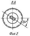
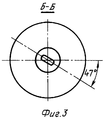
Поставленная задача решается тем, что предлагаемая конструкция насадки гидропескоструйного перфоратора содержит корпус, в котором проточный коноидальный щелевидный канал выполнен винтовым с углом поворота его продольной оси в интервале от 20 до 60°, причем отношение площадей выходного и входного отверстий оптимально в диапазоне 1:1,5-1:3.The problem is solved in that the proposed design of the nozzle of a sandblasting punch contains a housing in which a flowing conoidal slit-like channel is made screw with an angle of rotation of its longitudinal axis in the range from 20 to 60 °, and the ratio of the areas of the outlet and inlet openings is optimal in the range 1: 1, 5-1: 3.
Только данная совокупность отличительных признаков: переменное сечение канала, выполнение его винтовым для обеспечения заданного угла вращения абразивного потока в интервале 20-60° и уменьшение площади сечения щелевидного канала на выходе по отношению к входному в оптимальном диапазоне 1,5-3 обеспечивает достижение поставленной задачи, а именно: снизить до минимума гидравлическое сопротивление, соответственно увеличивая энергию и проникающую способность струи при разрушении горной породы. Изменение вектора потока под заявляемым углом в насадке изменяет и интенсифицирует гидродинамику разрушения и вымыва горной породы благодаря исключению встречного наложения атакующего и отработанного потоков. Достигается многократное увеличение поверхности фильтрации.Only this set of distinctive features: a variable channel cross-section, screwing it to provide a given angle of rotation of the abrasive flow in the range of 20-60 ° and reducing the cross-sectional area of the slit-like channel at the outlet relative to the input in the optimal range of 1.5-3 ensures the achievement of the task namely, to reduce the hydraulic resistance to a minimum, correspondingly increasing the energy and penetrating ability of the jet during the destruction of the rock. Changing the flow vector at the claimed angle in the nozzle changes and intensifies the hydrodynamics of the destruction and leaching of the rock due to the elimination of the onset of attacking and spent flows. A multiple increase in the filtration surface is achieved.
Изобретение поясняется чертежами, где на фиг.1 показано продольное сечение насадки, на фиг.2 - вид А-А, на фиг.3 - вид В-В.The invention is illustrated by drawings, where figure 1 shows a longitudinal section of a nozzle, figure 2 is a view aa, figure 3 is a view bb.
Насадка перфоратора состоит из корпуса 1, в котором выполнены каналы 2 с коноидальной частью на входе, переходом на винтообразный с завершением щелевидным сечением.The perforator nozzle consists of a housing 1, in which channels 2 are made with a conoidal part at the inlet, transition to a helical one with the completion of a slit-like section.
Насадка перфоратора работает следующим образом. Абразивный поток поступает через коноидальный вход канала в его винтовую часть, где происходит изменение вектора потока под углом 20-60°, что интенсифицирует гидродинамику разрушения и вымыва горных пород. Вращение абразивного потока позволяет исключить встречное наложение атакующего и отработанного потоков абразива. В то же время достигается увеличение проникающей способности струи за счет лучшего сохранения кинетической энергии и осевой скорости благодаря выполнению проточного канала щелевидным переменного сечения с заданным уменьшением от входа потока к его выходу.The hammer drill works as follows. The abrasive flow enters through the conoidal inlet of the channel into its screw part, where the flow vector changes at an angle of 20-60 °, which intensifies the hydrodynamics of the destruction and leaching of rocks. The rotation of the abrasive flow eliminates the oncoming overlap of the attacking and spent abrasive flows. At the same time, an increase in the penetrating ability of the jet is achieved due to the better conservation of kinetic energy and axial velocity due to the implementation of the flow channel with a slit-like variable cross section with a predetermined decrease from the flow inlet to its outlet.
Использование предлагаемых струйных насадок в гидропескоструйных перфораторах при всех равных условиях с другими позволяет более совершенно вскрывать пласты, способствуя хорошему притоку нефти, газа и конденсата.The use of the proposed jet nozzles in sandblasting punchers, all conditions being equal with others, allows for more complete opening of formations, contributing to a good flow of oil, gas and condensate.
Источники информации, принятые во внимание:Sources of information taken into account:
1. Авторское свидетельство СССР №7325050, кл. Е 21 В 43/114 от 28.06.1977.1. USSR copyright certificate No. 7325050, class. E 21 B 43/114 of 06/28/1977.
2. Авторское свидетельство СССР №211474, кл. Е 21 В 43/114 от 09.10.1965.2. USSR author's certificate No. 2111474, cl. E 21 B 43/114 of 09/10/1965.
Claims (1)
Priority Applications (1)
| Application Number | Priority Date | Filing Date | Title |
|---|---|---|---|
| RU2000114867/03A RU2247227C2 (en) | 2000-06-14 | 2000-06-14 | Jet end piece for hydraulic sand jet perforator |
Applications Claiming Priority (1)
| Application Number | Priority Date | Filing Date | Title |
|---|---|---|---|
| RU2000114867/03A RU2247227C2 (en) | 2000-06-14 | 2000-06-14 | Jet end piece for hydraulic sand jet perforator |
Publications (2)
| Publication Number | Publication Date |
|---|---|
| RU2000114867A RU2000114867A (en) | 2002-05-20 |
| RU2247227C2 true RU2247227C2 (en) | 2005-02-27 |
Family
ID=35286561
Family Applications (1)
| Application Number | Title | Priority Date | Filing Date |
|---|---|---|---|
| RU2000114867/03A RU2247227C2 (en) | 2000-06-14 | 2000-06-14 | Jet end piece for hydraulic sand jet perforator |
Country Status (1)
| Country | Link |
|---|---|
| RU (1) | RU2247227C2 (en) |
Cited By (6)
| Publication number | Priority date | Publication date | Assignee | Title |
|---|---|---|---|---|
| RU2448241C1 (en) * | 2010-10-04 | 2012-04-20 | Общество с ограниченной ответственностью "Нефть-Сервис" | Nozzle for hydraulic jet perforator |
| RU2482928C1 (en) * | 2012-03-20 | 2013-05-27 | Олег Савельевич Кочетов | Kochetov's gas-drop jet generator |
| RU2542023C2 (en) * | 2013-06-13 | 2015-02-20 | Михаил Анатольевич Камышев | Water injection nozzle for abrasive jet perforator |
| RU2567247C2 (en) * | 2010-07-15 | 2015-11-10 | Треви С.П.А. | Head for forcing of consolidating liquid mixes at pressure |
| RU2576296C1 (en) * | 2015-02-06 | 2016-02-27 | Олег Савельевич Кочетов | Kochetov(s vortex foam generator |
| RU2742163C1 (en) * | 2020-04-21 | 2021-02-02 | федеральное государственное бюджетное образовательное учреждение высшего образования «Томский государственный университет систем управления и радиоэлектроники» | Method for drying formed raw brick |
Citations (6)
| Publication number | Priority date | Publication date | Assignee | Title |
|---|---|---|---|---|
| US3467211A (en) * | 1963-09-24 | 1969-09-16 | Gulf Research Development Co | Drill bit for hydraulic jet drilling of wells |
| DE3124876A1 (en) * | 1981-06-25 | 1983-01-13 | Schako Metallwarenfabrik Ferdinand Schad Kg, 7201 Kolbingen | "WIDE THROWING NOZZLE" |
| RU2058831C1 (en) * | 1991-11-26 | 1996-04-27 | Юрий Михайлович Ермаков | Hood to device for feeding fluid medium |
| RU2081308C1 (en) * | 1993-01-15 | 1997-06-10 | Научно-технический центр по подземному хранению газонефтепродуктов и захоронению промышленных отходов | Long-range hydraulic apparatus for creating spaces in soluble rock formations |
| RU2099114C1 (en) * | 1996-04-19 | 1997-12-20 | Юрий Михайлович Ермаков | Nozzle for device for supply of moving medium |
| RU2128086C1 (en) * | 1997-12-18 | 1999-03-27 | Ермаков Юрий Михайлович | Adjustable nozzle for feeding of fluid medium |
-
2000
- 2000-06-14 RU RU2000114867/03A patent/RU2247227C2/en not_active IP Right Cessation
Patent Citations (6)
| Publication number | Priority date | Publication date | Assignee | Title |
|---|---|---|---|---|
| US3467211A (en) * | 1963-09-24 | 1969-09-16 | Gulf Research Development Co | Drill bit for hydraulic jet drilling of wells |
| DE3124876A1 (en) * | 1981-06-25 | 1983-01-13 | Schako Metallwarenfabrik Ferdinand Schad Kg, 7201 Kolbingen | "WIDE THROWING NOZZLE" |
| RU2058831C1 (en) * | 1991-11-26 | 1996-04-27 | Юрий Михайлович Ермаков | Hood to device for feeding fluid medium |
| RU2081308C1 (en) * | 1993-01-15 | 1997-06-10 | Научно-технический центр по подземному хранению газонефтепродуктов и захоронению промышленных отходов | Long-range hydraulic apparatus for creating spaces in soluble rock formations |
| RU2099114C1 (en) * | 1996-04-19 | 1997-12-20 | Юрий Михайлович Ермаков | Nozzle for device for supply of moving medium |
| RU2128086C1 (en) * | 1997-12-18 | 1999-03-27 | Ермаков Юрий Михайлович | Adjustable nozzle for feeding of fluid medium |
Cited By (6)
| Publication number | Priority date | Publication date | Assignee | Title |
|---|---|---|---|---|
| RU2567247C2 (en) * | 2010-07-15 | 2015-11-10 | Треви С.П.А. | Head for forcing of consolidating liquid mixes at pressure |
| RU2448241C1 (en) * | 2010-10-04 | 2012-04-20 | Общество с ограниченной ответственностью "Нефть-Сервис" | Nozzle for hydraulic jet perforator |
| RU2482928C1 (en) * | 2012-03-20 | 2013-05-27 | Олег Савельевич Кочетов | Kochetov's gas-drop jet generator |
| RU2542023C2 (en) * | 2013-06-13 | 2015-02-20 | Михаил Анатольевич Камышев | Water injection nozzle for abrasive jet perforator |
| RU2576296C1 (en) * | 2015-02-06 | 2016-02-27 | Олег Савельевич Кочетов | Kochetov(s vortex foam generator |
| RU2742163C1 (en) * | 2020-04-21 | 2021-02-02 | федеральное государственное бюджетное образовательное учреждение высшего образования «Томский государственный университет систем управления и радиоэлектроники» | Method for drying formed raw brick |
Similar Documents
| Publication | Publication Date | Title |
|---|---|---|
| US4391339A (en) | Cavitating liquid jet assisted drill bit and method for deep-hole drilling | |
| US6029746A (en) | Self-excited jet stimulation tool for cleaning and stimulating wells | |
| US5542486A (en) | Method of and apparatus for single plenum jet cutting | |
| US5199512A (en) | Method of an apparatus for jet cutting | |
| US2838284A (en) | Rotary drill bit | |
| US5992763A (en) | Nozzle and method for enhancing fluid entrainment | |
| CN103806836B (en) | Self-advancing type rotating jet jet rose | |
| RU2422626C1 (en) | Tool of hydro-dynamic treatment for medium of super-high erodibility | |
| EP0131451A2 (en) | Improvements in drilling equipment | |
| US20100288562A1 (en) | nozzle with channels that impart an angular momentum to the exiting fluid and methods for making and using same | |
| US5775446A (en) | Nozzle insert for rotary rock bit | |
| RU2247227C2 (en) | Jet end piece for hydraulic sand jet perforator | |
| RU2448242C1 (en) | Intensification method of hydrocarbon flow from productive formations of wells and cavitating device for its implementation | |
| RU2073089C1 (en) | Device for treatment of bottom-hole formation zone | |
| CN106246107A (en) | A kind of radially horizontal well compound broken rock high-pressure nozzle of self-advancing type | |
| RU2161237C1 (en) | Downhole hydraulic vibrator | |
| CA2482362C (en) | Service tool with flow diverter and associated method | |
| RU2186929C2 (en) | Hydroacoustic drill bit | |
| RU2713846C1 (en) | Cavitation device for stimulation of oil recovery of formations | |
| US10550668B2 (en) | Vortices induced helical fluid delivery system | |
| SU939732A1 (en) | Apparatus for declaying and mud injection into well walls | |
| RU2065024C1 (en) | Method for drilling with slit deposition | |
| EP1502002B1 (en) | Well completion with merged influx of well fluids | |
| RU2006567C1 (en) | Cutting-and-shearing drill bit | |
| RU34962U1 (en) | Device for colmatization of walls of permeable reservoirs of oil and gas wells |
Legal Events
| Date | Code | Title | Description |
|---|---|---|---|
| MM4A | The patent is invalid due to non-payment of fees |
Effective date: 20040615 |