RU2262995C2 - Piezoelectric device for ultrasonic cleaning of aircraft filters - Google Patents
Piezoelectric device for ultrasonic cleaning of aircraft filters Download PDFInfo
- Publication number
- RU2262995C2 RU2262995C2 RU2003133648/12A RU2003133648A RU2262995C2 RU 2262995 C2 RU2262995 C2 RU 2262995C2 RU 2003133648/12 A RU2003133648/12 A RU 2003133648/12A RU 2003133648 A RU2003133648 A RU 2003133648A RU 2262995 C2 RU2262995 C2 RU 2262995C2
- Authority
- RU
- Russia
- Prior art keywords
- filter
- cleaning
- washing
- solution
- unit
- Prior art date
Links
- 238000004506 ultrasonic cleaning Methods 0.000 title claims description 6
- 238000005406 washing Methods 0.000 claims abstract description 84
- 238000004140 cleaning Methods 0.000 claims abstract description 59
- 238000001035 drying Methods 0.000 claims abstract description 30
- 229910052757 nitrogen Inorganic materials 0.000 claims abstract description 5
- 239000003599 detergent Substances 0.000 claims description 21
- 239000012528 membrane Substances 0.000 claims description 9
- 238000011010 flushing procedure Methods 0.000 claims description 6
- 238000002360 preparation method Methods 0.000 claims description 5
- 239000003638 chemical reducing agent Substances 0.000 claims description 2
- 239000007788 liquid Substances 0.000 abstract description 5
- 238000001914 filtration Methods 0.000 abstract description 4
- 238000012544 monitoring process Methods 0.000 abstract description 4
- 230000000694 effects Effects 0.000 abstract description 3
- 239000000126 substance Substances 0.000 abstract 1
- 239000000243 solution Substances 0.000 description 79
- 239000000356 contaminant Substances 0.000 description 11
- 239000007789 gas Substances 0.000 description 9
- 238000012545 processing Methods 0.000 description 7
- 238000005086 pumping Methods 0.000 description 7
- 239000008399 tap water Substances 0.000 description 6
- 235000020679 tap water Nutrition 0.000 description 6
- ZGTMUACCHSMWAC-UHFFFAOYSA-L EDTA disodium salt (anhydrous) Chemical compound [Na+].[Na+].OC(=O)CN(CC([O-])=O)CCN(CC(O)=O)CC([O-])=O ZGTMUACCHSMWAC-UHFFFAOYSA-L 0.000 description 3
- 238000013461 design Methods 0.000 description 3
- 239000002184 metal Substances 0.000 description 3
- 229910052751 metal Inorganic materials 0.000 description 3
- 238000000034 method Methods 0.000 description 3
- -1 polypropylene Polymers 0.000 description 3
- IJGRMHOSHXDMSA-UHFFFAOYSA-N Atomic nitrogen Chemical compound N#N IJGRMHOSHXDMSA-UHFFFAOYSA-N 0.000 description 2
- 239000004743 Polypropylene Substances 0.000 description 2
- 239000007864 aqueous solution Substances 0.000 description 2
- 230000015572 biosynthetic process Effects 0.000 description 2
- 238000007664 blowing Methods 0.000 description 2
- 238000004891 communication Methods 0.000 description 2
- 238000005516 engineering process Methods 0.000 description 2
- 239000006260 foam Substances 0.000 description 2
- 238000009434 installation Methods 0.000 description 2
- 229920001155 polypropylene Polymers 0.000 description 2
- 230000005855 radiation Effects 0.000 description 2
- 229910001220 stainless steel Inorganic materials 0.000 description 2
- 239000010935 stainless steel Substances 0.000 description 2
- 238000009423 ventilation Methods 0.000 description 2
- XLYOFNOQVPJJNP-UHFFFAOYSA-N water Chemical compound O XLYOFNOQVPJJNP-UHFFFAOYSA-N 0.000 description 2
- 101150115489 MPK7 gene Proteins 0.000 description 1
- 239000004677 Nylon Substances 0.000 description 1
- 238000004026 adhesive bonding Methods 0.000 description 1
- 230000000712 assembly Effects 0.000 description 1
- 238000000429 assembly Methods 0.000 description 1
- 230000000903 blocking effect Effects 0.000 description 1
- 230000001680 brushing effect Effects 0.000 description 1
- 239000003990 capacitor Substances 0.000 description 1
- 238000001311 chemical methods and process Methods 0.000 description 1
- 238000006243 chemical reaction Methods 0.000 description 1
- 238000004939 coking Methods 0.000 description 1
- 239000004020 conductor Substances 0.000 description 1
- 239000000470 constituent Substances 0.000 description 1
- 238000011109 contamination Methods 0.000 description 1
- 230000007797 corrosion Effects 0.000 description 1
- 238000005260 corrosion Methods 0.000 description 1
- 238000010586 diagram Methods 0.000 description 1
- 239000012153 distilled water Substances 0.000 description 1
- 238000001704 evaporation Methods 0.000 description 1
- 230000008020 evaporation Effects 0.000 description 1
- 230000005284 excitation Effects 0.000 description 1
- 238000011049 filling Methods 0.000 description 1
- 238000007667 floating Methods 0.000 description 1
- 239000000446 fuel Substances 0.000 description 1
- 239000011521 glass Substances 0.000 description 1
- 231100001261 hazardous Toxicity 0.000 description 1
- 238000010438 heat treatment Methods 0.000 description 1
- 238000011068 loading method Methods 0.000 description 1
- 238000012423 maintenance Methods 0.000 description 1
- 238000004519 manufacturing process Methods 0.000 description 1
- 239000000463 material Substances 0.000 description 1
- 238000003032 molecular docking Methods 0.000 description 1
- 238000006386 neutralization reaction Methods 0.000 description 1
- 238000001208 nuclear magnetic resonance pulse sequence Methods 0.000 description 1
- 229920001778 nylon Polymers 0.000 description 1
- 239000002245 particle Substances 0.000 description 1
- 230000010363 phase shift Effects 0.000 description 1
- 239000004800 polyvinyl chloride Substances 0.000 description 1
- 230000003134 recirculating effect Effects 0.000 description 1
- 239000012261 resinous substance Substances 0.000 description 1
- 150000003839 salts Chemical class 0.000 description 1
- 238000000926 separation method Methods 0.000 description 1
- 230000035939 shock Effects 0.000 description 1
- 239000002904 solvent Substances 0.000 description 1
- 239000004094 surface-active agent Substances 0.000 description 1
- 238000002604 ultrasonography Methods 0.000 description 1
- 238000013022 venting Methods 0.000 description 1
- 238000003466 welding Methods 0.000 description 1
- 238000009736 wetting Methods 0.000 description 1
Images

Landscapes
- Cleaning By Liquid Or Steam (AREA)
Abstract
Description
Область техникиTechnical field
Изобретение относится к ультразвуковой очистке фильтроэлементов и фильтропакетов топливных, масляных, гидравлических и пневматических систем летательных аппаратов от механических частиц, смолистых веществ и продуктов коксования в моющих растворах с применением технологических эффектов явления кавитации в жидкости и может быть использовано в различных областях промышленности.The invention relates to ultrasonic cleaning of filter elements and filter packages of fuel, oil, hydraulic and pneumatic systems of aircraft from mechanical particles, resinous substances and coking products in washing solutions using technological effects of the phenomenon of cavitation in liquids and can be used in various industries.
Уровень техникиState of the art
Известно устройство для ультразвуковой очистки авиационных фильтроэлементов и фильтропакетов, содержащее ультразвуковой генератор, ванну с моющим раствором и блоком возвратно-поступательного перемещения фильтроэлементов и фильтропакетов и блок подготовки моющего раствора, содержащий бак, блок фильтров и насос подачи моющего раствора через блок фильтров в ванну, в стенки которой встроен кольцевой магнитострикционный преобразователь (А.В.Донской, O.K.Келлер, Г.С.Кратыш. Ультразвуковые электротехнологические установки. Ленинград, Энергоиздат, Ленинградское отделение, 1982 г., стр.148-149). За счет установки в ванне избыточного давления при перемещении фильтроэлементов и фильтропакетов происходит прямая прокачка через них моющего раствора. Недостатком данного устройства является недостаточное качество очистки, так как кавитационные течения в моющем растворе, возникающие под воздействием акустического излучения, имеют недостаточный уровень из-за преобразования электрической энергии в акустическую на одной частоте (один ультразвуковой генератор и один магнитострикционный преобразователь). Магнитострикционный преобразователь отличается низким коэффициентом полезного действия. Создание прямой прокачки моющего раствора при избыточном давлении в ванне достигается за счет сложных конструктивных решений, при этом такая прокачка не отличается высокой эффективностью. Применение только одной ванны с моющим раствором приводит к наличию на фильтроэлементах и фильтропакетах остатков моющего раствора, что требует дополнительной отмывки от них в других устройствах.A device for ultrasonic cleaning of aircraft filter elements and filter bags containing an ultrasonic generator, a bath with a washing solution and a block reciprocating movement of filter elements and filter bags and a block for preparing a washing solution containing a tank, a filter block and a pump for supplying a washing solution through the filter block to the bath, the walls of which an annular magnetostrictive converter is integrated (A.V. Donskoy, OKKeller, G.S. Kratysh. Ultrasonic electrotechnological installations. Leningrad, Energ Publishing House, Leningrad Branch, 1982, pp. 144-149). Due to the installation of excess pressure in the bath when moving the filter elements and filter bags, the washing solution is directly pumped through them. The disadvantage of this device is the insufficient quality of cleaning, since cavitation flows in the washing solution arising under the influence of acoustic radiation are insufficient due to the conversion of electrical energy into acoustic energy at one frequency (one ultrasonic generator and one magnetostrictive transducer). The magnetostrictive converter is characterized by a low efficiency. Creating a direct pumping of the washing solution at an overpressure in the bath is achieved due to complex structural solutions, while such pumping is not very efficient. The use of only one bath with a washing solution leads to the presence of residual cleaning solution on the filter elements and filter bags, which requires additional washing from them in other devices.
Наиболее близким к предлагаемому является устройство пьезоэлектрическое для ультразвуковой очистки авиационных фильтроэлементов, фильтропакетов и фильтров, которое содержит ванну с моющим раствором и N ультразвуковых генераторов, каждый из которых состоит из блока начального запуска, усилителя мощности, блока защиты от перегрузки, блока автоподстройки частоты и ультразвукового преобразователя, установленного на излучающей мембране и содержащего излучающую и тыльную накладки, между которыми расположены пьезоэлементы, при этом конструкционный выход ультразвукового преобразователя в виде рабочей поверхности излучающей накладки соединен с излучающей мембраной (Полезная модель №29249, МПК7 В 08 В 3/12). Устройство может использоваться для очистки от загрязнений в растворе технического моющего средства. Данное устройство может иметь блок подготовки моющего раствора, содержащий бак с нагревателями и датчиками контроля уровня и температуры, фильтр, обратный клапан и узел рециркуляции моющего раствора, вход которого через фильтр соединен с баком, а выход через обратный клапан с ванной. Для отмывки фильтроэлементов и фильтропакетов от раствора технического моющего средства данное устройство может иметь еще одно такое же пьезоэлектрическое устройство с блоком подготовки моющего раствора при количестве ультразвуковых генераторов К и использовании в качестве моющего раствора водопроводной воды. Для удаления остатков солей технического моющего средства в устройство может быть введена ванна ополаскивания с блоком подготовки раствора ополаскивания, содержащим бак с датчиком контроля уровня, фильтр, обратный клапан и узел рециркуляции раствора ополаскивания, вход которого через фильтр соединен с баком, а выход через обратный клапан с ванной ополаскивания. Устройство может также иметь блок сушки, содержащий вентилятор, нагреватель и камеру сушки с датчиком температуры, причем вентилятор через нагреватель соединен с камерой сушки. В каждой ванне с моющим раствором и раствором ополаскивания может быть установлен блок вращения фильтроэлементов и фильтропакетов.Closest to the proposed one is a piezoelectric device for ultrasonic cleaning of aviation filter elements, filter bags and filters, which contains a bath with a washing solution and N ultrasonic generators, each of which consists of an initial start-up unit, a power amplifier, an overload protection unit, an automatic frequency control unit and an ultrasonic a transducer mounted on a radiating membrane and containing a radiating and rear lining, between which are located the piezoelectric elements, while ruktsionny output of the ultrasonic transducer as the working surface of the radiating laths connected with the radiating membrane (utility model №29249, MPK7 In 08 3/12 in). The device can be used to clean contaminants in a solution of technical detergent. This device may have a washing solution preparation unit containing a tank with heaters and level and temperature control sensors, a filter, a check valve and a washing solution recirculation unit, the inlet of which is connected to the tank through a filter and the outlet through a check valve to the bathtub. For washing filter elements and filter bags from a solution of technical detergent, this device can have another piezoelectric device with a block for preparing a washing solution with the number of ultrasonic generators K and using tap water as a washing solution. To remove residual salts of technical detergent, a rinse bath can be introduced into the device with a rinse solution preparation unit containing a tank with a level control sensor, a filter, a check valve and a rinse solution recirculation unit whose inlet is connected to the tank through a filter and the outlet is through a check valve with a rinse bath. The device may also have a drying unit comprising a fan, a heater and a drying chamber with a temperature sensor, the fan being connected through the heater to the drying chamber. In each bath with a washing solution and a rinse solution, a rotation unit for filter elements and filter bags can be installed.
Недостатки данного устройства заключаются в следующем. Фильтроэлементы и фильтропакеты имеют цилиндрическую форму с внутренней полостью и работа их в летательных аппаратах заключается в прямом прокачивании жидкости или воздуха (снаружи через фильтрующую сетку во внутреннюю полость и из нее через выходное отверстие в отводящий трубопровод), то есть загрязнения накапливаются на наружной поверхности сетки и внутри окна ее ячеек. Под влиянием химических процессов воздействия поверхностно-активных веществ технического моющего средства и явления ультразвуковой кавитации происходит размягчение и удаление загрязнений с поверхности сетки фильтроэлементов и фильтропакетов. Однако при малых размерах окна ячеек сетки (например, от 5 до 16 мкм) удаление размягченных загрязнений непосредственно из окна ячейки даже под воздействием кавитации в некоторых ячейках происходит неполностью, причем часть этих загрязнений из окна ячейки попадает во внутреннюю полость и может остаться там и после завершения всех операций очистки. Устройство также не позволяет проводить операцию контроля герметичности фильтроэлементов и фильтропакетов (проверку на отсутствие повреждения фильтрующей сетки), что требует проводить эту операцию после завершения очистки и сушки, причем в пожароопасном растворителе, так как требуется естественное за счет испарения удаление влаги с фильтроэлементов и фильтропакетов по причине завершения очистки и сушки до этой операции.The disadvantages of this device are as follows. Filter elements and filter bags have a cylindrical shape with an internal cavity and their operation in aircraft consists in direct pumping of liquid or air (from the outside through the filter mesh into the internal cavity and from it through the outlet into the outlet pipe), that is, contaminants accumulate on the outer surface of the mesh and inside the window of her cells. Under the influence of chemical processes of the influence of surfactants of technical detergents and the phenomenon of ultrasonic cavitation, softening and removal of contaminants from the surface of the mesh of filter elements and filter bags occurs. However, for small window sizes of mesh cells (for example, from 5 to 16 μm), softened contaminants are removed directly from the cell window even under the influence of cavitation in some cells, and some of these contaminants from the cell window enter the internal cavity and may remain there after completion of all cleaning operations. The device also does not allow the operation of monitoring the tightness of filter elements and filter bags (checking for damage to the filter mesh), which requires this operation to be completed after cleaning and drying, and in a fire hazardous solvent, since moisture removal from the filter elements and filter bags that is natural due to evaporation is required by reason for completing cleaning and drying before this operation.
Сущность изобретенияSUMMARY OF THE INVENTION
Задачами, на решение которых направлено заявляемое техническое решение, является повышение качества очистки и совершенствование контроля герметичности фильтроэлементов и фильтропакетов. Техническими результатами, полученными при осуществлении устройства, являются повышение эффективности кавитации за счет введения обратного прокачивания моющего раствора и импульсов воздуха через фильтроэлементы и фильтропакеты и механической очистки щетками наружной поверхности фильтродисков фильтропакетов, расширение технологических возможностей за счет удаления остатков раствора технического моющего средства продувкой воздухом и проведения контроля герметичности фильтроэлементов и фильтропакетов в пожаробезопасном растворе технического моющего средства. Указанные технические результаты достигаются тем, что в устройстве, содержащем технологические позиции очистки в растворе технического моющего средства, промывки водопроводной водой от раствора технического моющего средства, ополаскивания в растворе ополаскивания и сушки нагретым воздухом, где каждая из позиции очистки, промывки и ополаскивания состоит из ванны с соответствующим моющим раствором и по крайней мере одним блоком вращения фильтроэлементов и фильтропакетов и блока подготовки моющего раствора, содержащего бак с нагревателями и датчиками контроля уровня и температуры моющего раствора, фильтр, обратный клапан и узел рециркуляции моющего раствора, вход которого через фильтр соединен с баком, а выход - через обратный клапан с ванной, позиции очистки и промывки содержат соответственно N и К ультразвуковых генераторов, каждый из которых состоит из блока начального запуска, усилителя мощности, блока защиты от перегрузки, блока автоподстройки частоты и ультразвукового преобразователя, установленного на излучающей мембране, содержащего излучающую и тыльную накладки, между которыми расположены пьезоэлементы, и соединенного конструкционным выходом в виде рабочей поверхности излучающей накладки с излучающей мембраной, а позиция сушки содержит вентилятор, нагреватель и камеру сушки с датчиком температуры нагретого воздуха, при этом вентилятор через нагреватель соединен с камерой сушки, - между позициями очистки и промывки введена позиция контроля герметичности фильтроэлементов и фильтропакетов, содержащая ванну с пожаробезопасным моющим раствором и блоком вращения фильтроэлементов и фильтропакетов и обратный клапан, соединенный через напоромер и редуктор с сетью сжатого газа, на позиции очистки и промывки выход узла рециркуляции моющего раствора соединен через воздушный клапан с сетью сжатого воздуха для его импульсной подачи во внутреннюю полость фильтроэлементов и фильтропакетов, на позиции очистки, промывки, контроля герметичности и ополаскивания введена кассета для размещения фильтроэлементов и фильтропакетов, состыкованная с обратным клапаном и блоком вращения и выполненная с возможностью вращения в ней фильтроэлементов и фильтропакетов с обеспечением герметичного ввода моющего раствора, сжатого газа и сжатого воздуха из обратного клапана во внутреннюю полость фильтроэлементов и фильтропакетов и прокачки из нее через фильтрующую сетку фильтроэлементов и фильтропакетов в ванну с моющим раствором, а на позиции очистки введены щетки механической очистки наружной поверхности фильтродисков фильтропакетов, установленные на кассете, и воздушный пистолет для удаления из фильтроэлементов и фильтропакетов остатков моющего раствора.The tasks to which the claimed technical solution is directed is to improve the quality of cleaning and improve the tightness control of filter elements and filter bags. The technical results obtained during the implementation of the device are to increase the efficiency of cavitation due to the introduction of reverse pumping of the washing solution and air pulses through the filter elements and filter bags and mechanical brushing of the outer surface of the filter discs of the filter bags, expanding technological capabilities by removing residual technical detergent solution by blowing air and tightness control of filter elements and filter bags in a fireproof solution e technical detergent. These technical results are achieved by the fact that in a device containing technological positions for cleaning in a solution of technical detergent, washing with tap water from a solution of technical detergent, rinsing in a solution of rinsing and drying with heated air, where each of the positions of cleaning, washing and rinsing consists of a bath with an appropriate detergent solution and at least one block of rotation of the filter elements and filter bags and the block for the preparation of the washing solution containing the tank the elements and sensors for monitoring the level and temperature of the washing solution, the filter, the non-return valve and the recirculation unit of the washing solution, the inlet of which is connected to the tank through the filter and the outlet through the non-return valve with a bath, the cleaning and washing positions contain N and K ultrasonic generators, respectively of which consists of an initial start-up block, a power amplifier, an overload protection block, an automatic frequency block and an ultrasonic transducer mounted on a radiating membrane containing a radiating and rear adki, between which there are piezoelectric elements, and connected by a structural output in the form of a working surface of a radiating lining with a radiating membrane, and the drying position contains a fan, a heater and a drying chamber with a temperature sensor for heated air, while the fan is connected through the heater to the drying chamber, between positions for cleaning and flushing, the position of monitoring the tightness of filter elements and filter bags was introduced, containing a bath with a fireproof washing solution and a rotation block of filter elements and a filter bags and a non-return valve connected through a pressure gauge and a reducer to the compressed gas network at the cleaning and washing positions, the outlet of the washing solution recirculation unit is connected through the air valve to the compressed air network for its pulsed supply to the internal cavity of filter elements and filter bags, to the cleaning and washing positions, tightness and rinsing control introduced a cartridge to accommodate filter elements and filter bags, docked with a check valve and a rotation unit and configured to rotate the filter in it elements and filter bags to ensure that the washing solution, compressed gas and compressed air are sealed from the non-return valve into the internal cavity of the filter elements and filter bags and pumped therefrom through the filter mesh of the filter elements and filter bags into the bath with the washing solution, and brushes for mechanically cleaning the outer surface are introduced filter disks of filter bags installed on the cartridge, and an air gun to remove residual cleaning solution from filter elements and filter bags.
Перечень чертежейList of drawings
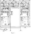
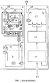
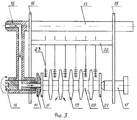
На фиг.1 приведен пример схемы построения устройства. На фиг.2 приведен пример построения блок-схемы ультразвукового генератора. На фиг.3 приведен пример размещения фильтропакета в кассете.Figure 1 shows an example of a circuit for constructing a device. Figure 2 shows an example of building a block diagram of an ultrasonic generator. Figure 3 shows an example of placing a filter bag in a cartridge.
Возможность осуществления изобретенияThe possibility of carrying out the invention
Устройство, как показано на фиг.1, состоит из технологических позиций очистки 1, контроля герметичности 2, промывки 3, ополаскивания 4 и сушки 5, представляющих из себя функционально законченные наборы взаимосвязанных блоков, узлов и элементов, установленных в едином каркасе 6, выполненном, например, из прямоугольных металлических труб или уголков.The device, as shown in Fig. 1, consists of technological positions for cleaning 1,
Каждая из технологических позиций, кроме позиции сушки 5, содержит ванну 7, выполненную из тонколистовой нержавеющей стали, с моющим раствором 8 и блоком вращения 9 фильтроэлементов 10 и фильтропакетов 11 (см. фиг.3) и обратный клапан 12. С блоком вращения 9, выполненным, например, в виде вала с поперечным штифтом зацепления, приводимого во вращение установленной на нем звездочкой за счет цепной передачи от общего привода (на фиг.1 не показан), и обратным клапаном 12 состыкована кассета 13, в которой через резиновую заглушку 14 крепится фильтроэлемент 10 или фильтропакет 11. Кассета 13 (см. фиг.3) состоит из стоек 15, на которых установлен трубопровод 16, обеспечивающий подачу моющего раствора 8 через отверстие в заглушке 14 во внутреннюю полость фильтроэлемента 10 или фильтропакета 11 и служащий своей верхней частью в качестве ручки для перемещения кассеты 13, прижимного фиксатора 17 и вала 18, обеспечивающего передачу вращения от блока вращения 9 и моющего раствора 8 от обратного клапана 12 к фильтроэлементу 10 или фильтропакету 11. Обратный клапан 12 устроен так, что он открывается в прямом направлении (к фильтроэлементу 10 или фильтропакету 11) при стыковке с ним кассеты 13 (при введении в него трубопровода 16) и закрывается при расстыковке. Фильтропакет 11 может быть как в собранном, так и в разобранном виде. В последнем случае фильтропакет 11 состоит из полого цилиндра, на котором фильтродиски 19 устанавливаются через втулки 20 и фиксируются резьбовой гайкой 21. Полый цилиндр имеет прорези, через которые моющий раствор проходит из внутренней полости фильтродисков 19 через их фильтрующую сетку в ванну 7. Для механической очистки наружной поверхности фильтродисков 19 на стойках 15 кассеты 13 установлен держатель 22 со щетками 23, выполненными, например, из пучков жесткой капроновой лески, установленных на проволочных стержнях.Each of the technological positions, except for the
Позиции очистки 1, промывки 3 и ополаскивания 4 содержат блок подготовки моющего раствора, состоящий из бака 24 с нагревателями 25, датчиками контроля уровня 26, выполненными, например, в виде кондуктометрических одноэлектродных стержней и контролирующими верхний (уровень залива) и нижний (аварийный уровень) уровни моющего раствора 8, и датчиком температуры 27, представляющим из себя стандартный термопреобразователь сопротивления и используемым для измерения и регулирования температуры моющего раствора 8, фильтра 28 грубой очистки моющего раствора 8, выполненного, например, в виде металлической сетки с размером ячейки 0,63×0,63 мм, узла рециркуляции 29, имеющего в своем составе, например, насос 30, обратный клапан 31 и фильтр 32 тонкой очистки моющего раствора 8, выполненный на основе типовых авиационных фильтроэлементов, и обратного клапана 12. Бак 24 соединен через фильтр 28 с входом узла рециркуляции 29, выход которого через обратный клапан 12 соединен с ванной 7. На позициях очистки 1 и промывки 3 узел рециркуляции 29 соединен через воздушный клапан 33, управляемый, например, с помощью пневмораспределителя, с сетью сжатого воздуха 34. На позиции 1 к сети сжатого воздуха 34 подсоединен воздушный пистолет 35 типовой конструкции.The
На позиции контроля герметичности 2 обратный клапан 12 соединен через стандартные напоромер 36 и редуктор 37 с сетью сжатого газа 38, в качестве которого могут быть использованы воздух или азот.At the position of the
Ванна 7 на позициях очистки 1, промывки 3 и ополаскивания 4 имеет системы перелива 39, обеспечивающую безаварийную работу режима рециркуляции моющего раствора 8, и слива в бак 24 (на фиг.1 не показана). Бак 24 имеет системы подачи соответствующего моющего раствора 8 из соответствующих магистралей, перелива и слива моющего раствора 8 в канализацию или систему нейтрализации (на фиг.1 не показаны).The
Позиции очистки 1 и промывки 3 содержат соответственно N и К ультразвуковых генераторов 40 (см. фиг.2), каждый из которых состоит из блока начального запуска 41, усилителя мощности 42, блока защиты от перегрузки 43, блока автоподстройки частоты 44 и ультразвукового преобразователя 45 (см. также фиг.1), установленного на излучающей мембране 46, являющейся дном или боковой стенкой ванны 7, и содержащего излучающую 47 и тыльную 48 накладки, между которыми расположены два пьезоэлемента 49. Конструкционный выход ультразвукового преобразователя 45 в виде рабочей поверхности 50 излучающей накладки 47 соединен с излучающей мембраной 46 посредством вваривания в отверстия в ней или приклейки к ее наружной поверхности. Ультразвуковой преобразователь 45 может быть установлен теми же способами на излучающей мембране 46, являющейся, например, частью погружного блока, размещенного внутри ванны 7. На фиг.2 приведен один из возможных вариантов связей между составными частями ультразвукового генератора 40. Выход усилителя мощности 42, выполненного, например, по двухтактной схеме, работающей в режиме переключения, через блок защиты от перегрузки 43, выполненный, например, на трансформаторе тока и формирователе сигнала блокировки, соединен с ультразвуковым преобразователем 45, который цепью обратной связи соединен с входом блока автоподстройки частоты 44, выполненного, например, на узле контроля тока и фазосдвигающей цепи. Усилитель мощности 42 имеет входы, соединенные с управляющими выходами блока начального запуска 41, выполненного, например, на основе динисторно-резисторно-конденсаторной цепи, блока защиты от перегрузки 43 и блока автоподстройки частоты 44. Соединения выполнены электрическими проводами и проводниками. Составные части ультразвуковых генераторов 40, кроме ультразвуковых преобразователей 45, могут быть расположены в отдельной стойке и на фиг.1 не изображены.The
Позиция сушки 5 содержит вентилятор 51, нагреватель 52 и камеру сушки 53 с датчиком температуры 27, при этом вентилятор 51 через нагреватель 52 связан с камерой сушки 53, имеющей выход 54 для связи с вытяжной вентиляцией 55 и выход 56 для рециркуляционной связи с вентилятором 51, соединенным дополнительно для подпитки рециркуляционного режима с наружным воздухом 57.The
Ванны 7 и камера сушки 53 закрыты крышками 58.
Все гидравлические и пневматические связи составных частей устройства выполнены металлическими, полипропиленовыми и полихлорвиниловыми трубопроводами. Все конструкционные части вышеприведенных блоков, узлов и элементов, контактирующие с моющим раствором 8, сжатым воздухом, сжатым газом и воздухом сушки, выполнены из материалов, стойких к коррозии, например, нержавеющей стали и полипропилена.All hydraulic and pneumatic connections of the component parts of the device are made of metal, polypropylene and PVC pipes. All structural parts of the above blocks, assemblies and elements in contact with the
В качестве моющего раствора 8 могут использоваться: на позициях очистки 1 и контроля герметичности 2 - водные растворы технических моющих средств, таких, например, как "Вертолин-74", "Синвал", "Импульс"; на позиции промывки 3 - водопроводная вода; на позиции ополаскивания 4 - водный раствор трилона Б или дистиллированная вода.As a
Устройство работает следующим образом.The device operates as follows.
Баки 24 заполняются соответствующими моющими растворами 8 до уровня залива, определяемого датчиком верхнего уровня 26. Моющий раствор 8 нагревается нагревателями 25 до соответствующей температуры, контролируемой при помощи датчика температуры 27 (например, 75±5°С для раствора на основе технического моющего средства "Вертолин-74", 40±10°С для водопроводной воды, 20±5°С для раствора трилона Б). В ванну 7 на позиции контроля герметичности заливается моющий раствор 8 соответствующей температуры (например, 20±5°С). В ванны 7 на позициях очистки 1, промывки 3 и ополаскивания 4 устанавливают пустые (без фильтроэлементов 10 и фильтропакетов 11) кассеты 13, обеспечивая введение трубопровода 16 в обратный клапан 12, а вала 18 в блок вращения 9, при этом обратный клапан 12 открывается в прямом направлении. Включают насосы 30 узлов рециркуляции 29, которые через фильтр 28 грубой очистки, обратный клапан 31, фильтр 32 тонкой очистки, обратный клапан 12 и кассету 13 закачивают моющий раствор 8 из баков 24 в ванны 7 до уровня перелива в систему перелива 39. Насосы 30 отключают. Заполнение ванн 7 можно производить без установки кассет 13 при использовании имитатора трубопровода 16. Обратный клапан 31 предотвращает возврат моющего раствора 8 из ванны 7 в бак 24 после отключения насоса из возникающего разряжения в трубопроводах при работающем насосе. Из ванны 7 на позиции очистки 1 вынимают пустую кассету 13 и устанавливают в нее фильтроэлемент 10 через заглушку 14. Установив загруженную кассету 13 обратно в ванну 7, производят включение привода вращения и на позиции очистки 1 насоса 30, ультразвуковых генераторов 40 и подачу в импульсном режиме (например, подача - 1 с, пауза - 4 с) сжатого воздуха из сети сжатого воздуха 34 через воздушный клапан 33. При включении ультразвукового генератора 40 он начинает работать в режиме автоколебаний, возникающих за счет того, что ультразвуковой преобразователь 45 обладает выраженным индуктивно-емкостным характером, и усилитель мощности 42 начинает работать в режиме переключения на частоте, определяемой в первую очередь резонансными свойствами ультразвукового преобразователя 45. Ток, протекающий через ультразвуковой преобразователь 45, протекает и через блок автоподстройки частоты 44, который формирует на своем управляющем выходе напряжение обратной связи, пропорциональное этому току и имеющее фазовый сдвиг, зависящий от величины отклонения этого тока от тока механического резонанса ультразвукового преобразователя 45. Вследствие этого происходит автоматическая подстройка рабочей частоты усилителя мощности 42 на частоту механического резонанса ультразвукового преобразователя 45, обеспечивая максимальную акустическую мощность, отдаваемую в моющий раствор 8. Блок начального запуска 41 формирует последовательность импульсов, обеспечивающую гарантированный запуск ультразвукового генератора 40 для исключения отсутствия возбуждения или срывов генерации из-за изменения электромеханических характеристик ультразвукового преобразователя 45 при изменении нагрузки: изменение типа, уровня и температуры моющего раствора 8, объема и конфигурации обрабатываемого фильтроэлемента 10. Пьезоэлементы 49 преобразуют электрические сигналы ультразвуковой частоты в механические колебания рабочей поверхности 50 излучающей накладки 47, которые за счет распространения акустических колебаний в моющем растворе 8 создают в нем эффект кавитации - образование воздушных полостей с их последующим захлопыванием в виде микровзрыва, что обеспечивает создание ударных волн, отрывающих загрязнения от поверхности фильтроэлемента 10 и особенно эффективных при образовании воздушных полостей непосредственно на его поверхности, и интенсивных течений, возникающих за счет того, что каждый из ультразвуковых преобразователей 45 работает на собственной частоте, так как на практике невозможно изготовить все ультразвуковые преобразователи 45 с идентичными характеристиками, но не выходящей за пределы стандартного допуска на разрешенные для применения в ультразвуковых генераторах частоты (например, ±10% для частоты 44 кГц), что способствует эффективному удалению загрязнений с поверхности фильтроэлемента 10. Осуществляемая за счет узла рециркуляции 29 обратная (из внутренней полости фильтроэлемента 10 в ванну 7) прокачка моющего раствора 8 позволяет исключить попадание загрязнений внутрь фильтроэлемента 10 и способствует их удалению из окна ячеек фильтрующей сетки. Импульсная подача воздуха соответствующего давления позволяет получить последовательность жидкостной и воздушно-жидкостной струй через фильтроэлемент 10, что повышает степень удаления загрязнений из окна ячейки фильтрующей сетки. В дополнение к этому движущийся через фильтрующую сетку моющий раствор 8 под действием ультразвукового излучения совершает дополнительные колебания с ультразвуковой частотой, что способствует отрыванию загрязнений от сетки и качественному их удалению из окон ее ячеек. Вращение фильтроэлемента 10 обеспечивает его обработку по всей поверхности. После окончания требуемого времени обработки насос 30 и ультразвуковые генераторы 40 отключают, открывают крышку 58, вынимают кассету 13 с фильтроэлементом 10, дают стечь из него моющему раствору 8 и воздушным пистолетом 35, введя его ствол во входное отверстие трубопровода 16 кассеты 13, удаляют остатки моющего раствора 8, в особенности его пену, из внутренней полости фильтроэлемента 10. Аналогично проводится очистка фильтропакета 11.
При очистке фильтропакета 11 в разобранном виде действительный фильтропакет разбирают на фильтродиски 19 и устанавливают их на полый цилиндр через втулки 20, и фиксируют резьбовой гайкой 21. В соответствии с размером фильтродисков 19 устанавливают соответствующий вылет щеток 23 из держателя 22, чтобы щетки 23 касались наружной поверхности фильтродисков 19 при вращении фильтропакета 11. Установка фильтропакета 11 в кассету 13 и его очистка производится аналогично фильтроэлементу 10. В действительном фильтропакете 11 зазор между фильтродисками 19 отсутствует, поэтому отдельные загрязнения с наружной поверхности могут не удаляться. Эта проблема решается за счет наличия в фильтропакете 11 втулок 20 и щеток 23.When cleaning the
После очистки кассету 13 с фильтроэлементом 10 или фильтропакетом 11 устанавливают в ванну 7 на позиции контроля герметичности 2. Для фильтропакета 11 из кассеты 13 убирают держатель 22 со щетками 23. Уровень моющего раствора 8 устанавливают на определенную технологией величину выше верхней границы фильтроэлемента 10 или фильтропакета 11 (например, 20±2 мм), слив его излишков из ванны 7 в отдельную емкость. Открывают подачу на редуктор 37 сжатого газа из сети сжатого газа 38 соответствующего давления (например, 0,15-0,20 МПа), затем устанавливают редуктором величину давления сжатого газа, подаваемого внутрь фильтроэлемента 10 или фильтропакета 11, определенную технологией в зависимости от допустимой герметичности фильтрующей сетки, смачивающей способности и плотности моющего раствора 8 (например, из диапазона 0,002-0,008 МПа), увеличивая его от нуля и контролируя по напорометру 36. Появление отделяющихся от проверяемого фильтроэлемента 10 или фильтропакета 11 пузырьков газа при давлении ниже требуемого является признаком повреждения фильтрующей сетки или несоответствия ее тонкости фильтрации техническим условиям. Контроль герметичности ведут при вращении фильтроэлемента 10 или фильтропакета 11, поэтому можно точно определить места повреждения. Редуктором 37 снижают давление сжатого газа до нуля и закрывают его подачу. Кассету 13 с фильтроэлементом 10 или фильтропакетом 11 вынимают из ванны 7 на позиции контроля герметичности 2 и при исправном фильтроэлементе 10 или фильтродисках 19 фильтропакета 11 устанавливают в ванну 7 на позиции промывки 3 для отмывки фильтроэлемента 10 или фильтропакета 11 от остатков моющего раствора 8 с позиции очистки 1 и контроля герметичности 2. При степени повреждения фильтроэлемента 10 или фильтродисков 19 фильтропакета 11 выше допустимой нормы их бракуют и их дальнейшая обработка на устройстве не проводится, что снижает трудозатраты на очистку комплекта фильтроэлементов 10 и фильтропакетов 11.After cleaning, the
Обработка фильтроэлемента 10 или фильтропакета 11 на позиции промывки 3 аналогична обработке на позиции очистки 1, только проводится в водопроводной воде и без применения щеток 23 и воздушного пистолета 35. Для повышения качества отмывки может быть установлена постоянная подпитка бака 24 от магистрали подачи водопроводной воды для организации проточного режима (постепенного обмена водопроводной воды в баке 24 с одновременным удалением плавучих пеносоставляющих остатков моющего раствора 8 с позиции очистки 1 и контроля герметичности 2 через систему перелива в канализацию).Processing the
Аналогично проводят ополаскивание фильтроэлемента 10 или фильтропакета 11 раствором трилона Б на позиции ополаскивания 4 с тем отличием, что здесь не применяются ультразвуковые генераторы 40 и импульсная подача воздуха.The
Для удаления влаги фильтроэлемент 10 или фильтропакет 11 вынимают из кассеты 13 и укладывают в корзину (на фиг.1 не показана), которую устанавливают в камеру сушки 53 на позиции сушки 5, причем фильтропакет 11 предварительно разбирают и в корзину укладывают в разобранном виде. Включают вентилятор 51 и нагреватель 52. Вентилятор 51 забирает через фильтр наружный воздух 57 и прогоняет его через нагреватель 52 и камеру сушки 53 в рециркуляционном режиме - с выхода 56 камеры сушки 53 воздух через воздуховод поступает вновь в заборный патрубок вентилятора 51. Использование рециркуляционного режима и регулируемых заслонок выхода 54 позволяет достигнуть незначительного забора наружного воздуха 57 при оптимальном режиме сушки - минимальное потребление электрической энергии на нагрев за счет малого поступления холодного наружного воздуха 57 и эффективное удаление паров влаги в вытяжную вентиляцию 55 при незначительном, но достаточном удалении воздуха через выход 54. Информация с датчика температуры 27 обеспечивает нагрев воздуха до необходимого значения температуры в зоне камеры 53 (например, 90±10°С).To remove moisture, the
В процессе работы устройства нагреватели 25 и 52 с датчиками температуры 27 обеспечивают автоматическое поддерживание температуры моющих растворов 8 и воздуха сушки в требуемых пределах. Датчики 26 аварийного уровня обеспечивают безопасную работу нагревателей 25 и насосов 30. Крышки 58 в процессе обработки закрывают на всех позициях, кроме позиции контроля герметичности 2, при этом на позициях очистки 1 и промывки 3 имеются датчики положения крышки, обеспечивающие отключение ультразвуковых генераторов 40 при открывании крышки для снижения уровня шума и исключения контакта рук оператора с кавитирующим моющим раствором 8.In the process, the
При использовании специальных кассет вместо кассеты 13 устройство позволяет проводить очистку стеклянной тары и других изделий. При использовании корзины можно проводить очистку различных мелких деталей.When using special cartridges instead of
Таким образом предлагаемая конструкция пьезоэлектрического устройства для ультразвуковой очистки авиационных фильтроэлементов и фильтропакетов позволяет повысить качество очистки за счет следующих факторов:Thus, the proposed design of a piezoelectric device for ultrasonic cleaning of aircraft filter elements and filter bags can improve the quality of cleaning due to the following factors:
- более высокой эффективности кавитации, обеспеченной наложением на ультразвуковые колебания моющего раствора дополнительных ультразвуковых колебаний движущегося моющего раствора, возникающих при его обратном прокачивании через фильтроэлементы и фильтропакеты, и импульсов воздуха;- higher cavitation efficiency, ensured by the imposition on the ultrasonic vibrations of the washing solution of additional ultrasonic vibrations of the moving washing solution that occur when it is pumped back through the filter elements and filter bags, and air pulses;
- исключения попадания смываемых загрязнений внутрь фильтроэлементов и фильтропакетов и дополнительного механического воздействия (отрыва) на загрязнения в окнах ячеек фильтрующей сетки, обеспеченного введением обратного прокачивания моющего раствора и импульсов воздуха через фильтроэлементы и фильтропакеты;- eliminating the ingress of washable contaminants into the filter elements and filter bags and additional mechanical impact (separation) on the pollution in the windows of the filter mesh cells, provided by the introduction of back pumping of the cleaning solution and air pulses through the filter elements and filter bags;
- уменьшения остатков моющего раствора на позиции очистки путем продувки через фильтроэлементы и фильтропакеты сжатого воздуха воздушным пистолетом;- reducing the residues of the washing solution at the cleaning position by blowing through the filter elements and filter bags of compressed air with an air gun;
- более эффективного удаления загрязнений с фильтродисков фильтропакетов на позиции очистки совместным воздействием ультразвуковой кавитации и механической очистки наружной поверхности фильтродисков щетками;- more efficient removal of contaminants from the filter discs of the filter bags at the cleaning position by the combined action of ultrasonic cavitation and mechanical cleaning of the outer surface of the filter discs with brushes;
- эффективной взаимосвязи ультразвуковых генераторов, моющего раствора, сжатого воздуха, щеток и воздушного пистолета, обеспеченной введением кассеты, стыкуемой одновременно с обратным клапаном и блоком вращения и выполненной с обеспечением возможности герметичного ввода моющего раствора и импульсов сжатого воздуха из обратного клапана во внутреннюю полость фильтроэлементов и фильтропакетов при их вращении, позволяющей получить при ультразвуковом воздействии процесс обратной прокачки этих сред при одновременной механической обработке щетками наружной поверхности фильтродисков фильтропакетов, и возможностью введения воздушного пистолета во входное отверстие кассеты.- the effective relationship of ultrasonic generators, washing solution, compressed air, brushes and an air gun, provided by the introduction of the cartridge, joined simultaneously with the check valve and the rotation unit and made with the possibility of a tight input of the cleaning solution and pulses of compressed air from the check valve into the internal cavity of the filter elements and filter bags during their rotation, which allows to obtain a process of back pumping of these media under ultrasonic action with simultaneous mechanical processing Otke brushes filtrodiskov filtropaketov outer surface, and an air gun to inject into the inlet of the cassette.
Введение в конструкцию позиции контроля герметичности между позициями очистки и промывки позволяет расширить технические возможности устройства, проводить этот процесс в пожаробезопасном растворе технического моющего средства и снизить общую трудоемкость очистки.The introduction of the tightness control position between the cleaning and washing positions in the design allows expanding the technical capabilities of the device, conducting this process in a fireproof solution of technical detergent, and reducing the overall complexity of cleaning.
Claims (1)
Priority Applications (1)
| Application Number | Priority Date | Filing Date | Title |
|---|---|---|---|
| RU2003133648/12A RU2262995C2 (en) | 2003-11-18 | 2003-11-18 | Piezoelectric device for ultrasonic cleaning of aircraft filters |
Applications Claiming Priority (1)
| Application Number | Priority Date | Filing Date | Title |
|---|---|---|---|
| RU2003133648/12A RU2262995C2 (en) | 2003-11-18 | 2003-11-18 | Piezoelectric device for ultrasonic cleaning of aircraft filters |
Publications (2)
| Publication Number | Publication Date |
|---|---|
| RU2003133648A RU2003133648A (en) | 2005-05-10 |
| RU2262995C2 true RU2262995C2 (en) | 2005-10-27 |
Family
ID=35746393
Family Applications (1)
| Application Number | Title | Priority Date | Filing Date |
|---|---|---|---|
| RU2003133648/12A RU2262995C2 (en) | 2003-11-18 | 2003-11-18 | Piezoelectric device for ultrasonic cleaning of aircraft filters |
Country Status (1)
| Country | Link |
|---|---|
| RU (1) | RU2262995C2 (en) |
Cited By (2)
| Publication number | Priority date | Publication date | Assignee | Title |
|---|---|---|---|---|
| EP2410288A1 (en) * | 2010-07-20 | 2012-01-25 | Mitutoyo Corporation | Method for cleaning skid of surface roughness tester |
| RU2621801C1 (en) * | 2015-12-01 | 2017-06-07 | Общество с ограниченной ответственностью "Авиакомпания Волга-Днепр" | Piezoelectric device for ultrasonic cleaning aeronautical and filter elements and filtered discs and method of cleaning with its use |
Citations (2)
| Publication number | Priority date | Publication date | Assignee | Title |
|---|---|---|---|---|
| RU2193931C1 (en) * | 2001-03-29 | 2002-12-10 | Павленко Олег Григорьевич | Plant for ultrasonic cleaning of aircraft filter elements and filter stacks for flying vehicle liquid systems and method of cleaning with the aid of said plant |
| RU29249U1 (en) * | 2002-08-05 | 2003-05-10 | ОАО "ОКТБ Кристалл" | Piezoelectric device for ultrasonic cleaning of aviation filter elements, filter bags and filters |
-
2003
- 2003-11-18 RU RU2003133648/12A patent/RU2262995C2/en not_active IP Right Cessation
Patent Citations (2)
| Publication number | Priority date | Publication date | Assignee | Title |
|---|---|---|---|---|
| RU2193931C1 (en) * | 2001-03-29 | 2002-12-10 | Павленко Олег Григорьевич | Plant for ultrasonic cleaning of aircraft filter elements and filter stacks for flying vehicle liquid systems and method of cleaning with the aid of said plant |
| RU29249U1 (en) * | 2002-08-05 | 2003-05-10 | ОАО "ОКТБ Кристалл" | Piezoelectric device for ultrasonic cleaning of aviation filter elements, filter bags and filters |
Cited By (3)
| Publication number | Priority date | Publication date | Assignee | Title |
|---|---|---|---|---|
| EP2410288A1 (en) * | 2010-07-20 | 2012-01-25 | Mitutoyo Corporation | Method for cleaning skid of surface roughness tester |
| US9103656B2 (en) | 2010-07-20 | 2015-08-11 | Mitutoyo Corporation | Method for cleaning skid of surface roughness tester |
| RU2621801C1 (en) * | 2015-12-01 | 2017-06-07 | Общество с ограниченной ответственностью "Авиакомпания Волга-Днепр" | Piezoelectric device for ultrasonic cleaning aeronautical and filter elements and filtered discs and method of cleaning with its use |
Also Published As
| Publication number | Publication date |
|---|---|
| RU2003133648A (en) | 2005-05-10 |
Similar Documents
| Publication | Publication Date | Title |
|---|---|---|
| CN109013576B (en) | Hydraulic pipeline cleaning system for ship | |
| CA2852998A1 (en) | Method and apparatus for cleaning diesel particulate filters | |
| CN104923508A (en) | Ultrasonic cleaning device | |
| JPH02502353A (en) | Method and apparatus for filtering and homogenizing liquids | |
| CS232593B1 (en) | Equipment for cleaning of parts by means of near ultrasound field | |
| RU2621801C1 (en) | Piezoelectric device for ultrasonic cleaning aeronautical and filter elements and filtered discs and method of cleaning with its use | |
| Duran et al. | Design and Implementation of an Intelligent Ultrasonic Cleaning Device. | |
| RU2692787C1 (en) | Ultrasonic machine for pre-sterilization cleaning of medical products | |
| JP2017067412A (en) | Heat exchanger | |
| KR20120094586A (en) | Pipe cleaning apparatus using shock wave | |
| RU2262995C2 (en) | Piezoelectric device for ultrasonic cleaning of aircraft filters | |
| CN203635546U (en) | Ultrasonic automatic cleaning machine for medical apparatus and instruments | |
| CN103658100B (en) | Ultrasound wave refuse receptacle cleaning method | |
| CN203634107U (en) | Automatic dishwasher | |
| JP2011241867A (en) | Valve which can be cleaned and valve cleaning system | |
| RU2368435C2 (en) | Device for ultrasound cleaning of parts | |
| JP2003190716A (en) | Strainer provided with ultrasonic cleaning device and cleaning method thereof | |
| JP3330492B2 (en) | Easy-to-clean type filling machine unit, cleaning method and cleaning device for the unit | |
| CN110180829A (en) | A kind of internal medicine medical apparatus cleaning device | |
| JP2006516479A (en) | Ultrasonic cleaning tank | |
| CN220970079U (en) | With dual-purpose cleaning apparatus | |
| CN111058215A (en) | A clothing cleaning device based on ultrasonic cavitation effect | |
| KR20210065497A (en) | Combo tyope dish cleaner | |
| CN201959950U (en) | Ultrasonic cleaning equipment | |
| JP7535221B2 (en) | Crossflow wet classification device and wet classification method using the same |
Legal Events
| Date | Code | Title | Description |
|---|---|---|---|
| MM4A | The patent is invalid due to non-payment of fees |
Effective date: 20121119 |