RU2302000C2 - Mode and a system of marking and definition of identity of liquid hydrocarbons - Google Patents
Mode and a system of marking and definition of identity of liquid hydrocarbons Download PDFInfo
- Publication number
- RU2302000C2 RU2302000C2 RU2003135224/28A RU2003135224A RU2302000C2 RU 2302000 C2 RU2302000 C2 RU 2302000C2 RU 2003135224/28 A RU2003135224/28 A RU 2003135224/28A RU 2003135224 A RU2003135224 A RU 2003135224A RU 2302000 C2 RU2302000 C2 RU 2302000C2
- Authority
- RU
- Russia
- Prior art keywords
- marker
- fluid
- concentration
- source
- processor
- Prior art date
Links
Images


Classifications
-
- G—PHYSICS
- G01—MEASURING; TESTING
- G01N—INVESTIGATING OR ANALYSING MATERIALS BY DETERMINING THEIR CHEMICAL OR PHYSICAL PROPERTIES
- G01N33/00—Investigating or analysing materials by specific methods not covered by groups G01N1/00 - G01N31/00
- G01N33/26—Oils; Viscous liquids; Paints; Inks
- G01N33/28—Oils, i.e. hydrocarbon liquids
- G01N33/2835—Specific substances contained in the oils or fuels
- G01N33/2882—Markers
-
- Y—GENERAL TAGGING OF NEW TECHNOLOGICAL DEVELOPMENTS; GENERAL TAGGING OF CROSS-SECTIONAL TECHNOLOGIES SPANNING OVER SEVERAL SECTIONS OF THE IPC; TECHNICAL SUBJECTS COVERED BY FORMER USPC CROSS-REFERENCE ART COLLECTIONS [XRACs] AND DIGESTS
- Y10—TECHNICAL SUBJECTS COVERED BY FORMER USPC
- Y10T—TECHNICAL SUBJECTS COVERED BY FORMER US CLASSIFICATION
- Y10T436/00—Chemistry: analytical and immunological testing
- Y10T436/13—Tracers or tags
Landscapes
- Chemical & Material Sciences (AREA)
- Health & Medical Sciences (AREA)
- Engineering & Computer Science (AREA)
- Life Sciences & Earth Sciences (AREA)
- Analytical Chemistry (AREA)
- General Physics & Mathematics (AREA)
- General Chemical & Material Sciences (AREA)
- Food Science & Technology (AREA)
- Medicinal Chemistry (AREA)
- Physics & Mathematics (AREA)
- Chemical Kinetics & Catalysis (AREA)
- Biochemistry (AREA)
- General Health & Medical Sciences (AREA)
- Oil, Petroleum & Natural Gas (AREA)
- Immunology (AREA)
- Pathology (AREA)
- Analysing Materials By The Use Of Radiation (AREA)
- Other Investigation Or Analysis Of Materials By Electrical Means (AREA)
- Investigating Or Analyzing Non-Biological Materials By The Use Of Chemical Means (AREA)
- Investigating Or Analysing Materials By Optical Means (AREA)
- Control Of Non-Electrical Variables (AREA)
- Electrical Discharge Machining, Electrochemical Machining, And Combined Machining (AREA)
Abstract
Description
Область техникиTechnical field
Настоящее изобретение относится к жидким углеводородам, а более точно - к способам и системам маркировки и определения подлинности жидких углеводородов.The present invention relates to liquid hydrocarbons, and more specifically to methods and systems for marking and determining the authenticity of liquid hydrocarbons.
Предшествующий уровень техникиState of the art
Часто возникает необходимость идентифицировать источник жидкого углеводорода, такого как нефть, легроин, бензин, дизельное топливо, реактивное топливо, керосин, смазочные материалы, газ, сжиженный газ и т.п. Эта необходимость возникает, например, в случае подозрений на мошенничество, такое как хищение из трубопроводов, танкеров или хранилищ; намеренная или ненамеренная порча качества, разбавление, смешение текучей среды из разных источников, в случае разливов или утечек нефти из неопределенного источника в землю или в воду и т.п. Высокая стоимость и также уклонение от налогов обеспечивают прибыльность, которая значительно стимулирует злоумышленные действия в отношении текучих сред. Путем заблаговременной маркировки уязвимых в отношении подделок жидкостей обеспечивается возможность определить впоследствии, осталось ли исходное качество жидкости или она была подделана, разбавлена или испорчена.Often there is a need to identify the source of a liquid hydrocarbon, such as oil, legroin, gasoline, diesel, jet fuel, kerosene, lubricants, gas, liquefied gas, etc. This need arises, for example, in cases of suspected fraud, such as theft from pipelines, tankers or storage facilities; intentional or unintentional deterioration of quality, dilution, mixing of fluid from various sources, in the event of oil spills or leaks from an unspecified source into land or water, etc. The high cost and also tax evasion provide profitability, which significantly stimulates malicious actions in relation to fluids. By pre-marking liquids vulnerable to counterfeiting, it is possible to determine subsequently whether the original quality of the liquid remained or whether it was tampered with, diluted or damaged.
Известны способы и системы маркировки жидких углеводородов. Термины «жидкий углеводород», «нефть», «текучая среда» в данном документе используются как синонимы в самом широком смысле для обозначения всех текучих сред и жидкостей. Нефть, как правило, маркируют веществом, которое можно затем обнаружить, чтобы определить источник происхождения нефти. Этим веществом может быть, например, смешивающаяся с нефтью жидкость, которую добавляют в нефть и которая дает излучение на определенной длине волны при облучении светом или иным излучением. С нефтью смешивают простое красящее вещество, тем самым изменяют цвет нефти, в результате чего нефть можно идентифицировать в соответствии с маркирующим цветом. Либо маркирующее вещество может испускать излучение на невидимой длине волны, и при этом нефть идентифицируют путем измерения испускаемой длины волны в фотоприемнике. В других способах топливо маркируют органическим составом, наличие которого определяют спектрометром или хроматографом. Как правило, маркер должен отвечать определенным критериям, относящимся к данной маркированной текучей среде. Например, стоимость, легкость обнаружения, стабильность, растворимость и совместимость с данной текучей средой (например, воспламеняемость с маркированным топливом в двигателях), инертность по отношению к воздуху, воде и обычным составляющим почвы, коррозионная активность, летучесть и токсичность.Known methods and systems for labeling liquid hydrocarbons. The terms "liquid hydrocarbon", "oil", "fluid" in this document are used as synonyms in the broadest sense to refer to all fluids and liquids. Oil is usually labeled with a substance that can then be detected to determine the source of the oil. This substance may be, for example, a liquid miscible with oil, which is added to the oil and which produces radiation at a specific wavelength when irradiated with light or other radiation. A simple coloring matter is mixed with the oil, thereby changing the color of the oil, whereby the oil can be identified according to the marking color. Or the marking agent can emit radiation at an invisible wavelength, and the oil is identified by measuring the emitted wavelength in the photodetector. In other methods, the fuel is labeled with an organic compound, the presence of which is determined by a spectrometer or chromatograph. Typically, a marker must meet certain criteria related to a given labeled fluid. For example, cost, ease of detection, stability, solubility, and compatibility with a given fluid (e.g., flammability with marked fuel in engines), inertness with respect to air, water, and common soil constituents, corrosion activity, volatility, and toxicity.
В патенте США № 5598451 раскрыто устройство для измерения серы, содержащейся в нефти. Устройство содержит источник электропитания высокого напряжения, рентгеновскую трубку, фильтр, ячейку с пробой, рентгеновское окно, детектор рентгеновских лучей и измерительную схему. Источник электропитания высокого напряжения соединен с рентгеновской трубкой для генерирования рентгеновских лучей. Измерительная схема соединена с детектором рентгеновских лучей. Фильтр расположен между рентгеновской трубкой и ячейкой с пробой. Ячейка с пробой расположена между входным отверстием для пробы и выходным отверстием для пробы, и проба протекает через ячейку с пробой. Окно рентгеновских лучей расположено перед ячейкой с пробой. Рентгеновская трубка, фильтр, окно для пробы и детектор рентгеновских лучей установлены в таком положении, что рентгеновские лучи, испускаемые рентгеновской трубкой в сторону окна рентгеновских лучей и отражаемые окном рентгеновских лучей, попадают на детектор рентгеновских лучей.US Pat. No. 5,598,451 discloses a device for measuring sulfur contained in oil. The device comprises a high voltage power supply, an X-ray tube, a filter, a sample cell, an X-ray window, an X-ray detector, and a measurement circuit. A high voltage power supply is connected to the x-ray tube to generate x-rays. The measurement circuit is connected to an X-ray detector. The filter is located between the x-ray tube and the sample cell. The sample cell is located between the sample inlet and the sample outlet, and the sample flows through the sample cell. The x-ray window is located in front of the sample cell. The x-ray tube, filter, sample window, and x-ray detector are mounted in such a position that the x-rays emitted by the x-ray tube toward the x-ray window and reflected by the x-ray window are incident on the x-ray detector.
Рентгеновская трубка имеет мишень из титана. Окно рентгеновских лучей выполнено из бериллия. Проба содержит серу. Рентгеновские лучи, генерируемые рентгеновской трубкой и фильтруемые фильтром, попадают на ячейку с пробой через окно пробы. Флуоресцентные рентгеновские лучи, излучаемые серой в пробе, попадают на детектор рентгеновских лучей. Измерительная схема определяет весовую концентрацию серы, содержащейся в пробе, путем измерения интенсивности рентгеновских лучей по характеристике К-оболочки серы.The x-ray tube has a titanium target. The x-ray window is made of beryllium. The sample contains sulfur. X-rays generated by an X-ray tube and filtered by a filter enter the sample cell through the sample window. Fluorescent x-rays emitted by sulfur in the sample are incident on the x-ray detector. The measuring circuit determines the weight concentration of sulfur contained in the sample by measuring the intensity of x-rays according to the characteristic of the K-shell of sulfur.
В патенте США № 6214624 раскрыт способ маркировки жидкой среды с помощью перфторуглеродного изотопного индикатора. Перфторуглеродный индикатор растворяют, смешивают, рассеивают или эмульгируют в жидкой среде. На стадии обнаружения используют пробу жидкой среды на активированном углероде, десорбируют и пропускают по сильно окисляющему катализатору, такому как катализатор 10-25% V2O2/Al2O3, тем самым сжигая неперфторуглеродный материал. Воду удаляют из сожженной пробы с использованием полупроницаемой мембраны, а сожженную пробу вводят в газовый хроматограф со стандартным детектором, работающим по принципу захвата электрона, интерфейсом и записывающим устройством.US Pat. No. 6,214,624 discloses a method for marking a liquid medium with a perfluorocarbon isotope indicator. The perfluorocarbon indicator is dissolved, mixed, dispersed or emulsified in a liquid medium. At the detection stage, a sample of a liquid medium on activated carbon is used, stripped and passed through a highly oxidizing catalyst, such as a 10-25% V 2 O 2 / Al 2 O 3 catalyst, thereby burning non-perfluorocarbon material. Water is removed from the burnt sample using a semipermeable membrane, and the burnt sample is introduced into the gas chromatograph with a standard detector operating on the principle of electron capture, an interface and a recording device.
В патенте США № 6312958 раскрыт способ маркировки жидкостей по меньшей мере двумя маркирующими веществами и способ их обнаружения, в результате чего подделанная жидкость обнаруживается, даже если эта подделанная жидкость маркирована маркерами, аналогичными первоначальным маркерам. В этом патенте используются по меньшей мере два маркера с перекрывающими друг друга диапазонами поглощения, что позволяет использовать большое число маркеров в данном диапазоне длин волн. Соединения, используемые для искажения первоначальной жидкости, должны иметь не только пределы поглощения, аналогичные оригинальным маркерам, но также и характеристики, аналогичные оригинальным маркерам в остальном диапазоне поглощения. Каждый обманный маркер может иметь только один относительно узкий максимум поглощения, соответствующий максимуму оригинальных маркеров. Если источники света используются для испускания только в областях максимумов поглощения, то аналогичные спектры флуоресценции, вероятно, появятся в обоих случаях. Но если используются источники света, которые испускают излучение на длине волны, на которой маркеры-подделки не имеют поглощения, но на которых оригинальные маркеры имеют перекрывающие друг друга пределы поглощения, то тогда флуоресцентное излучение, испускаемое этими маркерами, обнаруживается в случае оригинальных маркеров, но не в случае поддельных маркеров.US Pat. No. 6,312,958 discloses a method for marking liquids with at least two marking agents and a method for detecting them, whereby a tampered liquid is detected even if the tampered liquid is marked with markers similar to the original markers. This patent uses at least two markers with overlapping absorption ranges, which allows the use of a large number of markers in this wavelength range. Compounds used to distort the initial liquid should have not only absorption limits similar to the original markers, but also characteristics similar to the original markers in the rest of the absorption range. Each deceptive marker can have only one relatively narrow absorption maximum corresponding to the maximum of the original markers. If light sources are used for emission only in the regions of absorption maxima, then similar fluorescence spectra are likely to appear in both cases. But if light sources are used that emit radiation at a wavelength at which counterfeit markers have no absorption, but at which the original markers have overlapping absorption limits, then the fluorescent radiation emitted by these markers is detected in the case of the original markers, but not in case of fake markers.
В патенте США № 5980593 раскрыт способ маркирования жидкого продукта группой маркеров и способ идентификации жидкого продукта. Маркером является соединение, синтезированное этерификацией соответствующей линейной или разветвленной С1-С18 алкилкарбоксильной кислоты. Согласно этому способу С5-С10 алкилкарбоксильные кислоты применяют для маркировки топлива, благодаря пониженной интерференции от фоновой флуоресценции. Концентрация маркера в жидком нефтепродукте обычно составляет по меньшей мере 0,25 частей на миллион (чмл).US Pat. No. 5,980,593 discloses a method for labeling a liquid product with a group of markers and a method for identifying a liquid product. The marker is a compound synthesized by esterification of an appropriate linear or branched C 1 -C 18 alkylcarboxylic acid. According to this method, C 5 -C 10 alkyl carboxylic acids are used for fuel labeling due to reduced interference from background fluorescence. The concentration of the marker in a liquid petroleum product is usually at least 0.25 ppm.
Маркер можно выделить из меченого нефтепродукта с помощью раствора, состоящего на 5-60 об.% из смешиваемого с водой, несмешиваемого с нефтью растворителя-мостика, из воды, минерального щелочного источника, такого как КОН, и/или алкил- или алкокосиамина. Для определения на месте соответствующий объем водной выделяемой смеси смешивают с соответствующим объемом проверяемой жидкой нефти. Если маркер присутствует в жидкой нефти, то он будет выделен водным слоем и будет флуоресцировать при реакции с выделяемой смесью. Для качественного обнаружения маркера используют ручной источник УФ-излучения. Согласно этому способу возможно определить уровни маркера приблизительно до значений 5%. Например, топливо было помечено маркером в количестве 3 чмл, растворенным в изооктане. Маркер был выделен и проверен под ультрафиолетовой лампой и дал флуоресцентное свечение, указавшее на присутствие маркера.The marker can be isolated from the labeled oil using a solution consisting of 5-60 vol.% Of a water-miscible, water-immiscible bridge solvent, water, a mineral alkaline source such as KOH, and / or an alkyl or alkocosiamine. To determine in situ, the appropriate volume of the aqueous emitted mixture is mixed with the corresponding volume of the tested liquid oil. If the marker is present in liquid oil, then it will be isolated by the aqueous layer and will fluoresce upon reaction with the emitted mixture. For high-quality marker detection, a manual UV source is used. According to this method, it is possible to determine marker levels to approximately 5%. For example, fuel was marked with a marker in the amount of 3 chl dissolved in isooctane. The marker was isolated and tested under an ultraviolet lamp and gave a fluorescent glow indicating the presence of the marker.
Краткое изложение существа изобретенияSummary of the invention
В основу настоящего изобретения поставлена задача создания способа и системы для маркировки текучей среды и для определения подлинности текучей среды.The basis of the present invention is the task of creating a method and system for marking a fluid and to determine the authenticity of the fluid.
Поставленная задача решается согласно изобретению путем создания системы для маркировки текучей среды маркером, в котором текучая среда вытекает из источника к месту назначения. Система содержит датчик для определения свойств текучей среды и регулятор расхода текучей среды для введения определенного количества маркера в текучую среду. Определенное количество определяется по значению текучей среды и по заданной концентрации маркера в текучей среде на месте.The problem is solved according to the invention by creating a system for marking a fluid marker, in which the fluid flows from the source to the destination. The system comprises a sensor for determining fluid properties and a fluid flow regulator for introducing a certain amount of marker into the fluid. A certain amount is determined by the value of the fluid and the given concentration of the marker in the fluid in place.
Согласно еще одному аспекту предложен способ маркировки текучей среды маркером, которая течет из источника к месту назначения. Способ заключается в измерении свойств текучей среды, определении количества вводимого в текучую среду маркера согласно измеряемому свойству и введении определенного количества в текучую среду, тем самым маркируя текучую среду.In yet another aspect, a method is provided for marking a fluid with a marker that flows from a source to a destination. The method consists in measuring the properties of the fluid, determining the amount of the marker introduced into the fluid according to the measured property and introducing a certain amount into the fluid, thereby marking the fluid.
Согласно еще одному аспекту предложен способ определения подлинности текучей среды. Способ включает в себя этапы сравнения концентрации первичного маркера в текучей среде с заданной концентрацией и определения первой подлинности текучей среды согласно результату этого сравнения. Способ также включает этапы повышения концентрации вторичного маркера в текучей среде, и если первая подлинность положительна, то определяют наличие вторичного маркера в текучей среде и определяют вторую подлинность текучей среды согласно результату этапа определения наличия вторичного маркера.According to another aspect, a method for determining the authenticity of a fluid is provided. The method includes the steps of comparing the concentration of the primary marker in the fluid with a given concentration and determining the first authenticity of the fluid according to the result of this comparison. The method also includes the steps of increasing the concentration of the secondary marker in the fluid, and if the first authenticity is positive, then determining the presence of the secondary marker in the fluid and determining the second authenticity of the fluid according to the result of the step of determining the presence of the secondary marker.
Краткое описание чертежейBrief Description of the Drawings
В дальнейшем изобретение поясняется описанием предпочтительных вариантов воплощения со ссылками на сопровождающие чертежи, на которых:The invention is further explained in the description of the preferred embodiments with reference to the accompanying drawings, in which:
Фиг.1 изображает блок-схему системы для маркировки текучей среды, согласно изобретению;Figure 1 depicts a block diagram of a system for marking a fluid according to the invention;
Фиг.2 - блок-схему второго варианта выполнения системы маркировки текучей среды, согласно изобретению;Figure 2 is a block diagram of a second embodiment of a fluid marking system according to the invention;
Фиг.3 - блок-схему еще одного варианта выполнения системы маркировки текучей среды, согласно изобретению;Figure 3 is a block diagram of another embodiment of a fluid marking system according to the invention;
Фиг.4 - блок-схему еще одного варианта выполнения системы маркировки текучей среды, согласно изобретению;4 is a block diagram of another embodiment of a fluid marking system according to the invention;
Фиг.5 - блок-схему еще одного варианта выполнения системы маркировки текучей среды, согласно изобретению;5 is a block diagram of another embodiment of a fluid marking system according to the invention;
Фиг.6 - блок-схему еще одного варианта выполнения системы маркировки текучей среды, согласно изобретению;6 is a block diagram of another embodiment of a fluid marking system according to the invention;
Фиг.7 - блок-схему еще одного варианта выполнения системы маркировки текучей среды, согласно изобретению;7 is a block diagram of another embodiment of a fluid marking system according to the invention;
Фиг.8 - блок-схему еще одного варианта выполнения системы маркировки текучей среды, согласно изобретению;Fig. 8 is a block diagram of yet another embodiment of a fluid marking system according to the invention;
Фиг.9 - блок-схему еще одного варианта выполнения системы маркировки текучей среды, согласно изобретению;9 is a block diagram of another embodiment of a fluid marking system according to the invention;
Фиг.10 - блок-схему еще одного варианта выполнения системы маркировки текучей среды, согласно изобретению.10 is a block diagram of another embodiment of a fluid marking system according to the invention.
Описание предпочтительных вариантов выполнения изобретенияDescription of preferred embodiments of the invention
Согласно изобретению предложены система и способ регулирования количества маркера, вводимого в немаркированную текучую среду, в которых обеспечивается заданная концентрация маркера в текучей среде. При этом в немаркированную текучую среду можно ввести комбинацию нескольких маркеров, каждый - с заданной концентрацией.The invention provides a system and method for controlling the amount of marker introduced into an unlabelled fluid, in which a predetermined concentration of the marker in the fluid is provided. In this case, a combination of several markers, each with a given concentration, can be introduced into an unlabelled fluid.
Термин «текучая среда» относится к любому жидкому углеводороду, включая нефтепродукты, переработанные и непереработанные, такие как сырая нефть, легроин, бензин, дизельное топливо, реактивное топливо, керосин, пропан, смазочные материалы (например, моторное масло), рабочая жидкость, природный газ (либо газообразный, либо сжиженный). На сопровождающих чертежах сплошными линиями обозначены линии течения текучей среды, пунктирными линиями обозначены линии связи, линии управления сигналами и линии измерительных сигналов - как радиосигналов, так и проводных сигналов.The term “fluid” refers to any liquid hydrocarbon, including refined and non-refined petroleum products such as crude oil, legroin, gasoline, diesel fuel, jet fuel, kerosene, propane, lubricants (eg motor oil), working fluid, natural gas (either gaseous or liquefied). In the accompanying drawings, solid lines indicate fluid flow lines, dotted lines indicate communication lines, signal control lines, and measurement signal lines of both radio signals and wired signals.
Система 50 (Фиг.1) маркировки текучей среды содержит источник 52 маркера, регулятор 54 расхода текучей среды (РТТС), процессор 56 и датчик 58. Регулятор 54 расхода текучей среды может быть либо насосом, либо клапаном. В приводимом ниже описании регулятор 54 расхода текучей среды является насосом. Регулятор 54 расхода текучей среды содержит входное отверстие 60 и выходное отверстие.The fluid labeling system 50 (FIG. 1) includes a marker source 52, a fluid flow controller (PTTC) 54, a processor 56, and a sensor 58. The fluid flow controller 54 may be either a pump or a valve. In the following description, the fluid flow controller 54 is a pump. The fluid flow controller 54 includes an inlet 60 and an outlet.
Источник 52 маркера содержит маркер (не показан), который является стабильным, смешивается с маркируемой текучей средой и совместим с ней. Например, маркер отвечает таким требованиям, как экологичность (т.е. он не вреден для воздуха, воды, компонентов почвы, живых организмов), некоррозионный, нелетучий, нетоксичный, совместим с оборудованием, которое работает с данной текучей средой (например, двигатель, топливный элемент, гидравлическая система, которая использует данную текучую среду, тормозная система, автоматическая трансмиссия).Marker source 52 contains a marker (not shown) that is stable, mixes with, and is compatible with, a marked fluid. For example, a marker meets such requirements as environmental friendliness (i.e. it is not harmful to air, water, soil components, living organisms), non-corrosive, non-volatile, non-toxic, compatible with equipment that works with this fluid (for example, an engine, fuel cell, hydraulic system that uses the given fluid, brake system, automatic transmission).
Согласно одному варианту маркер может быть приготовлен на основе алкана - СnH2n+2, где n=1, 2, 3... По меньшей мере один атом водорода замещен элементом, который может быть обнаружен анализатором флуоресценции рентгеновских лучей (АФРЛ). Получаемое соединение имеет общую формулу СnH2n+2-mХm, где n=1, 2, 3... и m=1, 2, 3... «Х» - любой элемент, который можно обнаружить с помощью АФРЛ. Простым примером этого элемента является литий (Li), щелочной металл, который формирует одну ковалентную связь с атомом углерода.According to one embodiment, the marker can be prepared on the basis of an alkane — C n H 2n + 2 , where n = 1, 2, 3 ... At least one hydrogen atom is replaced by an element that can be detected by an X-ray fluorescence analyzer (AFL). The resulting compound has the general formula C n H 2n + 2-m X m , where n = 1, 2, 3 ... and m = 1, 2, 3 ... "X" is any element that can be detected using AFRL. A simple example of this element is lithium (Li), an alkali metal that forms one covalent bond with a carbon atom.
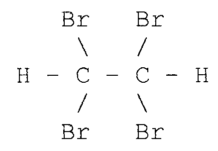
Согласно другому варианту маркер может быть галогенным соединением, таким как галид алкила общей формулы СnH2n+2-mХm, где n=1, 2, 3... и m=1, 2, 3... «Х» - галоген, такой как фтор (F), хлор (Cl), бром (Br) и йод (I). Примером такого галида алкила является тетрабромэтан - C2H2Br4, структурная формула которогоIn another embodiment, the marker may be a halogen compound, such as an alkyl halide of the general formula C n H 2n + 2-m X m , where n = 1, 2, 3 ... and m = 1, 2, 3 ... "X "- halogen, such as fluorine (F), chlorine (Cl), bromine (Br) and iodine (I). An example of such an alkyl halide is tetrabromoethane - C 2 H 2 Br 4 , whose structural formula
Химические названия и молекулярные формулы некоторых примеров маркера в виде галида алкила:The chemical names and molecular formulas of some examples of an alkyl halide marker:
1,1,2,2-тетрахлорэтан (С2H2Cl4); 1,1,2-трихлорэтан (С2H3Cl3); пентахлорэтан (С2HCl5); гексахлорэтан (С2Cl6); 1,2,4-трихлорбензол (С6H9Cl3); 1,2,4,5-тетрахлорбензол (С6H8Cl4); йодид этил (С2H5I); бромид этила (С2H5Br); дихлор-1,2-дибромэтан (С2H2Cl2Br2); дихлортрибромэтан (С2HCl2Br3); дифтор-1-хлорэтан (С2H3F2Cl); дифтор-1,2-дибромэтан (С2H2F2Br2); трифтор-1,2,2-дибромэтан (С2HF3Br2); трибромпропан (С2H7Br3); дибромбензол (С6H10Br2); дибромэтан (С2H4Br4); n-пропилбромид (С3H7Br); парабромфторбензол (С6H10FBr) структурной формулы1,1,2,2-tetrachloroethane (C 2 H 2 Cl 4 ); 1,1,2-trichloroethane (C 2 H 3 Cl 3 ); pentachloroethane (C 2 HCl 5 ); hexachloroethane (C 2 Cl 6 ); 1,2,4-trichlorobenzene (C 6 H 9 Cl 3 ); 1,2,4,5-tetrachlorobenzene (C 6 H 8 Cl 4 ); ethyl iodide (C 2 H 5 I); ethyl bromide (C 2 H 5 Br); dichloro-1,2-dibromoethane (C 2 H 2 Cl 2 Br 2 ); dichlorotribromethane (C 2 HCl 2 Br 3 ); difluoro-1-chloroethane (C 2 H 3 F 2 Cl); difluoro-1,2-dibromoethane (C 2 H 2 F 2 Br 2 ); trifluoro-1,2,2-dibromoethane (C 2 HF 3 Br 2 ); tribromopropane (C 2 H 7 Br 3 ); dibromobenzene (C 6 H 10 Br 2 ); dibromoethane (C 2 H 4 Br 4 ); n-propyl bromide (C 3 H 7 Br); parabromofluorobenzene (C 6 H 10 FBr) of the structural formula
![]()
![]()
бромид бутила (С4H9Br); бромид октила (С8H15Br).butyl bromide (C 4 H 9 Br); octyl bromide (C 8 H 15 Br).
Для приготовления текучей среды в газообразном состоянии можно использовать газообразные маркеры. Например, метан (CH4) находится в газообразном состоянии в обычных условиях. Галогены могут заменить атомы водорода согласно формуле СН4-mXm, где m=1, 2, 3, 4. «Х» - галоген фтор (F), хлор (Cl), бром (Br) и йод (I) или щелочной металл литий (Li). Этими маркерами могут быть, например, бромид метила (CH3Br), йодид метила (CH3I), бромхлорметан (CH2BrCl) и т.п.Gaseous markers can be used to prepare a fluid in a gaseous state. For example, methane (CH 4 ) is in a gaseous state under normal conditions. Halogens can replace hydrogen atoms according to the formula CH 4-m X m , where m = 1, 2, 3, 4. “X” is halogen fluorine (F), chlorine (Cl), bromine (Br) and iodine (I) or alkali metal lithium (Li). These markers may be, for example, methyl bromide (CH 3 Br), methyl iodide (CH 3 I), bromochloromethane (CH 2 BrCl) and the like.
Согласно другому варианту маркером может быть органометаллическое или галогенное соединение, в котором по меньшей мере один металлический элемент или по меньшей мере один галоген связан по меньшей мере с одним атомом углерода алкена (олефина) общей формулы С2(H2n+1-mCn)4Xm, где n=1, 2, 3..., m=1, 2, 3... «Х» - либо щелочной металл, либо галоген. Примером этого соединения является бромэтилен с молекулярной формулой С2H3Br.In another embodiment, the marker may be an organometallic or halogen compound in which at least one metal element or at least one halogen is bonded to at least one carbon atom of an alkene (olefin) of general formula C 2 (H 2n + 1-m C n ) 4 X m , where n = 1, 2, 3 ..., m = 1, 2, 3 ... "X" is either an alkali metal or halogen. An example of this compound is bromethylene with the molecular formula C 2 H 3 Br.
Согласно еще одному варианту маркером может быть любое из указанных выше соединений, в которых кремний (Si), германий (Ge) замещает атом углерода. Например, диэтилсилан (С4H12Si) является таким соединением. Необходимо отметить, что кремний можно детектировать с помощью АФРЛ и при этом замещать атомы водорода не нужно. Соответственно, «Х»-элементы не являются необходимыми в этом соединении, если кремний, германий служат в качестве маркирующего элемента, обнаруживаемого с помощью АФРЛ. Для алканов общей формулой является Сn-mH2n+2Ym, где n=1, 2, 3..., m=1, 2, 3..., m<n и где Y обозначает кремний, германий и т.п. Для алкенов (олефинов) общая формула соединения - С2(H2n+1Cn-m)4Ym, где n=1, 2, 3..., m=1, 2, 3... и где Y обозначает кремний, германий и т.п.In yet another embodiment, the marker may be any of the above compounds in which silicon (Si), germanium (Ge) replaces a carbon atom. For example, diethylsilane (C 4 H 12 Si) is such a compound. It should be noted that silicon can be detected using AFLR and, at the same time, it is not necessary to replace hydrogen atoms. Accordingly, “X” elements are not necessary in this compound if silicon, germanium serve as a marking element detected by AFL. For alkanes, the general formula is C nm H 2n + 2 Y m , where n = 1, 2, 3 ..., m = 1, 2, 3 ..., m <n, and where Y is silicon, germanium, etc. P. For alkenes (olefins), the general formula of the compound is C 2 (H 2n + 1 C nm ) 4 Y m , where n = 1, 2, 3 ..., m = 1, 2, 3 ... and where Y is silicon Germany, etc.
Маркер может иметь вид текучей среды (т.е. газ или жидкость) или твердого вещества (например, порошок, смешиваемое тело и т.п.), может быть радиоактивным или нерадиоактивным. Источник 52 маркера может содержать разные типы маркеров.The marker may be in the form of a fluid (i.e., gas or liquid) or a solid (e.g., powder, miscible body, etc.), may be radioactive or non-radioactive. Token source 52 may contain different types of tokens.
Регулятор 54 расхода текучей среды может быть насосом известного типа, таким как импульсный насос, который подает заданный объем текучей среды при каждом ходе поршня. Регулятор 54 расхода текучей среды может быть либо насосом постоянного объема или насосом переменной производительности. Датчик 58 может быть температурным датчиком, расходомером, вискозиметром, ареометром или их сочетанием. Датчик 58 может содержать оптическое устройство, устройство для измерения диэлектрической проницаемости, спектрометр, анализатор флуоресценции рентгеновских лучей (АФРЛ), газовый хроматограф, детектор излучения, детектор ультразвука или их комбинации.The fluid flow controller 54 may be a pump of a known type, such as a pulse pump, which delivers a predetermined volume of fluid at each stroke of the piston. The fluid flow controller 54 may be either a constant displacement pump or a variable displacement pump. The sensor 58 may be a temperature sensor, a flow meter, a viscometer, a hydrometer, or a combination thereof. The sensor 58 may include an optical device, a device for measuring permittivity, a spectrometer, an X-ray fluorescence analyzer (AFLR), a gas chromatograph, a radiation detector, an ultrasound detector, or a combination thereof.
Процессор 56 является цифровым процессором (ЦП), микросхемой (МС) и т.п. Процессор 56 соединен с регулятором 54 расхода текучей среды и с датчиком 58. Источник 52 маркера соединен со входным отверстием 60. Выходное отверстие 62 соединено с трубопроводом 64 в точке 66 введения маркера. Текучая среда протекает по трубопроводу 64 от источника немаркированной текучей среды (не показан) к месту назначения маркированной текучей среды (не показано).The processor 56 is a digital processor (CPU), a microcircuit (MS), and the like. The processor 56 is connected to a fluid flow controller 54 and to a sensor 58. The marker source 52 is connected to an inlet 60. The outlet 62 is connected to a conduit 64 at a marker introduction point 66. Fluid flows through conduit 64 from a source of unlabelled fluid (not shown) to the destination of the labeled fluid (not shown).
Необходимо отметить, что текучую среду можно направлять или хранить от источника к месту назначения посредством любого средства хранения или доставки - подземное нефтехранилище, буровая на шельфе, резервуар в нефтеперерабатывающем заводе, на электростанции, в генераторе электроэнергии, на газовой станции, в транспортном средстве доставки нефти (автоцистерне, танкере или средстве доставки по воздуху), в обитаемом объекте (жилой дом, больница, гостиница, ресторан, универмаг, супермаркет, служебное здание, научно-исследовательское учреждение, военная база, аэропорт, производственное предприятие), в наземном транспортном средстве (автомобиль, грузовик, автобус, вагон, мотоцикл, военная техника, снегоход и т.п.), летательном аппарате (самолет, вертолет, самолет-амфибия, воздушный шар, беспилотное воздушное судно, ракета, управляемый реактивный снаряд, космический корабль), судне (грузовое, пассажирское, гидроцикл, катер).It should be noted that the fluid can be directed or stored from the source to the destination by any means of storage or delivery - an underground oil storage facility, an offshore drilling rig, a tank in an oil refinery, a power plant, an electric power generator, a gas station, an oil delivery vehicle (tanker, tanker or airborne delivery vehicle), in an inhabited facility (apartment building, hospital, hotel, restaurant, department store, supermarket, office building, research institution Ie, military base, airport, manufacturing enterprise), in a land vehicle (car, truck, bus, wagon, motorcycle, military equipment, snowmobile, etc.), aircraft (airplane, helicopter, amphibian, balloon , unmanned aircraft, rocket, guided missile, space ship), ship (cargo, passenger, jet ski, boat).
Текучая среда течет в трубопроводе 64 от источника немаркированной жидкости к месту назначения маркированной жидкости либо под действием силы тяжести, либо с помощью насоса (не показан). Датчик 58 соединен с трубопроводом 64 в измерительном пункте 68. Измерительный пункт 68 может быть расположен либо до точки 66 введения маркера, либо после нее.Fluid flows in conduit 64 from a source of unlabelled fluid to the destination of the labeled fluid, either by gravity or by a pump (not shown). The sensor 58 is connected to the pipe 64 in the measuring point 68. The measuring point 68 can be located either to the point 66 of the introduction of the marker, or after it.
Датчик 58 определяет значение по меньшей мере одного свойства текучей среды, которая течет по трубопроводу 64, например, температуру, расход, вязкость, плотность и концентрация вещества в текучей среде. Свойство измеряют, чтобы определить количество маркера, вводимого в текучую среду, и поэтому концентрация маркера в маркируемой текучей среде регулируется по существу точно. Датчик 58 может измерять диэлектрическую проницаемость, уровень излучения, длину волны испускаемого светового излучения, уровень атомной энергии, частоту и амплитуду атомных колебаний, концентрацию вещества в текучей среде и аналогичные физические характеристики, по которым можно определить требуемое свойство.The sensor 58 determines the value of at least one property of the fluid that flows through conduit 64, for example, temperature, flow rate, viscosity, density and concentration of a substance in the fluid. The property is measured to determine the amount of marker introduced into the fluid, and therefore, the concentration of the marker in the marked fluid is controlled substantially precisely. The sensor 58 can measure the dielectric constant, the radiation level, the wavelength of the emitted light radiation, the level of atomic energy, the frequency and amplitude of atomic vibrations, the concentration of the substance in the fluid, and similar physical characteristics by which the desired property can be determined.
Датчик 58 измеряет значение свойства текучей среды, которая протекает по трубопроводу 64. Датчик 58 посылает сигнал, характеризующий измеренное свойство (или характеристику) в процессор 56. Процессор 56 определяет количество маркера, вводимого в текучую среду, путем обработки сигнала, принимаемого датчиком 58, и поэтому, когда вся текучая среда будет подана из источника немаркированной текучей среды к месту назначения маркированной текучей среды, тогда концентрация маркера в месте назначения маркированной текучей среды будет соответствовать выбранному значению. Либо процессор 56 определяет количество маркера, чтобы обеспечивать концентрацию маркера в протекающей текучей среде на выбранном уровне в течение всего срока протекания текучей среды от источника немаркированной текучей среды к месту назначения маркированной текучей среды. И в том, и в другом случаях процессор 56 определяет количество маркера по справочной таблице, алгоритму, базе данных (не показаны).A sensor 58 measures the property value of the fluid that flows through conduit 64. A sensor 58 sends a signal characterizing the measured property (or characteristic) to the processor 56. The processor 56 determines the amount of marker introduced into the fluid by processing the signal received by the sensor 58, and therefore, when all of the fluid is supplied from a source of unlabelled fluid to the destination of the labeled fluid, then the concentration of the marker at the destination of the labeled fluid will correspond selected value. Or, the processor 56 determines the amount of the marker in order to ensure the concentration of the marker in the flowing fluid at a selected level for the entire duration of the fluid flow from the source of unmarked fluid to the destination of the marked fluid. In both cases, the processor 56 determines the number of tokens from a lookup table, algorithm, database (not shown).
Процессор 56 управляет работой регулятора 54 расхода текучей среды, в результате чего регулятор 54 расхода текучей среды доставляет заданное количество маркера в протекающую текучую среду. Например, если регулятор 54 расхода текучей среды является объемным насосом постоянной производительности, то процессор 56 направляет сигнал в регулятор 54 расхода текучей среды, чтобы работать в течение заданного времени, в соответствии с заданным количеством. Если регулятор 54 расхода текучей среды является насосом переменной производительности, то процессор 56 направляет сигнал в регулятор 54 расхода текучей среды, и регулятор работает с таким расходом, чтобы подавать заданное количество маркера в протекающую текучую среду в течение заданного времени.The processor 56 controls the operation of the fluid flow controller 54, as a result of which the fluid flow controller 54 delivers a predetermined amount of the marker to the flowing fluid. For example, if the fluid flow controller 54 is a constant displacement volume pump, then the processor 56 sends a signal to the fluid flow controller 54 to operate for a predetermined time in accordance with a predetermined amount. If the fluid flow regulator 54 is a variable displacement pump, then the processor 56 sends a signal to the fluid flow regulator 54, and the regulator operates at such a flow rate as to supply a predetermined amount of marker to the flowing fluid for a predetermined time.
Таким образом, регулятор 54 расхода текучей среды доставляет то количество маркера, которое определено процессором 56, из источника 52 маркера в текучую среду в точке 66 введения маркера. Необходимо отметить, что концентрация маркера в протекающей текучей среде зависит по меньшей мере от одного свойства текучей среды в любое заданное время. Поэтому, чтобы обеспечить концентрацию маркера на постоянном заданном уровне, необходимо непрерывно измерять это свойство и необходимо, чтобы соответственно работал регулятор 54 расхода текучей среды.Thus, the fluid flow controller 54 delivers the amount of marker determined by the processor 56 from the marker source 52 to the fluid at the marker introduction point 66. It should be noted that the concentration of the marker in the flowing fluid depends on at least one property of the fluid at any given time. Therefore, in order to ensure the concentration of the marker at a constant predetermined level, it is necessary to continuously measure this property and it is necessary that the fluid flow regulator 54 accordingly operates.
Чтобы обеспечить постоянное значение концентрации маркера в протекающей текучей среде, необходимо вводить в текучую среду большее количество маркера, когда расход текучей среды в трубопроводе 64 повышается, и вводить меньшее количество, когда расход текучей среды понижается. Поэтому, если датчик 56 выполнен в виде расходомера, то он измеряет расход текучей среды, которая протекает в трубопроводе 64, и направляет соответствующий сигнал в процессор 56. Масса текучей среды, протекающей в течение определенного времени в трубопроводе 64 или сохраняемой в определенном объеме в емкости зависит от температуры, вязкости или плотности текучей среды, и поэтому количество маркера, вводимого в текучую среду, нужно регулировать соответствующим образом.In order to maintain a constant concentration of the marker in the flowing fluid, it is necessary to introduce a larger quantity of the marker into the fluid when the flow rate of the fluid in the conduit 64 increases, and to introduce a smaller amount when the flow rate of the fluid decreases. Therefore, if the sensor 56 is in the form of a flow meter, it measures the flow rate of the fluid that flows in the pipe 64, and sends the corresponding signal to the processor 56. The mass of the fluid flowing for a certain time in the pipe 64 or stored in a certain volume in the tank depends on the temperature, viscosity or density of the fluid, and therefore the amount of marker introduced into the fluid must be adjusted accordingly.
Если регулятором 54 расхода текучей среды является насос, то каждое введение данных о заданной концентрации маркера включает в себя данные о времени продолжительности работы насоса для каждого значения расхода текучей среды. Например, введенные данные о заданной концентрации маркера соответствуют времени работы насоса в течение 10 секунд за 1 минуту для расхода текучей среды 10000 л/ч. В этом случае регулятор 54 расхода текучей среды вводит, например, 55 мл маркера в течение 10 секунд работы. Если датчик 58 определил расход 12000 л/ч протекающей текучей среды в измерительном пункте 68, то процессор 56 дает указание регулятору 54 расхода текучей среды работать в течение 12 сек, при этом 66 мл маркера вводится в протекающую текучую среду и обеспечивается заданная концентрация.If the regulator 54 of the flow rate of the fluid is a pump, then each entry of data on a given concentration of the marker includes data on the duration of the pump for each value of the flow rate of the fluid. For example, the entered data on a given marker concentration corresponds to a pump operating time of 10 seconds per 1 minute for a flow rate of 10,000 l / h. In this case, the fluid flow control 54 introduces, for example, 55 ml of a marker within 10 seconds of operation. If the sensor 58 determines the flow rate of 12,000 l / h of flowing fluid in measuring point 68, then the processor 56 instructs the fluid flow control 54 to operate for 12 seconds, while 66 ml of the marker is introduced into the flowing fluid and a predetermined concentration is provided.
Регулятор 54 расхода текучей среды, процессор 56 и датчик 58 вместе образуют систему управления с обратной связью. При этом процессор 56 управляет работой регулятора 54 расхода текучей среды согласно обратному сигналу, принимаемому от датчика 58. Эта система управления с обратной связью позволяет системе 50 маркировки текучей среды обеспечивать концентрацию маркера на постоянном заданном значении, независимо от колебаний динамических свойств текучей среды, такой как температура, расход, вязкость, плотность и т.п. Таким образом, система 50 маркировки может обеспечивать по существу точную концентрацию маркера несмотря на колебания динамических свойств протекающей текучей среды.The fluid flow controller 54, processor 56, and sensor 58 together form a feedback control system. At the same time, the processor 56 controls the operation of the fluid flow controller 54 according to the feedback received from the sensor 58. This feedback control system allows the fluid marking system 50 to maintain the marker concentration at a constant predetermined value, regardless of fluctuations in the dynamic properties of the fluid, such as temperature, flow, viscosity, density, etc. Thus, the marking system 50 can provide a substantially accurate marker concentration despite fluctuations in the dynamic properties of the flowing fluid.
Обнаружено, что система 50 маркировки текучей среды может создавать концентрацию маркера 3 чмл с отклонением 5%. То есть можно обнаружить подделанную текучую среду, содержащую тот же маркер в количестве свыше 3,15 ч/млн или меньше 2,85 ч/млн.It has been found that the fluid labeling system 50 can produce a 3 ppm marker concentration with a deviation of 5%. That is, it is possible to detect a tampered fluid containing the same marker in an amount of more than 3.15 ppm or less than 2.85 ppm.
Следует отметить, что система 50 маркировки текучей среды может содержать дополнительные регуляторы расхода текучей среды, аналогичные регулятору 54 расхода текучей среды. Входное отверстие каждого регулятора расхода текучей среды соединено с источником маркера, а выходное отверстие каждого регулятора соединено с точкой введения маркера - аналогично точке 66 введения маркера. Каждый регулятор расхода текучей среды в свою очередь соединен с процессором. В этом случае в любое заданное время может работать один или более регуляторов расхода текучей среды. При этом если один из регуляторов расхода текучей среды неисправен и не работает, то работает другой регулятор расхода текучей среды.It should be noted that the fluid labeling system 50 may include additional fluid flow controllers similar to the fluid flow control 54. The inlet of each fluid flow regulator is connected to a marker source, and the outlet of each regulator is connected to a marker injection point, similarly to marker introduction point 66. Each fluid flow regulator is in turn connected to a processor. In this case, at any given time, one or more fluid flow controllers may operate. Moreover, if one of the fluid flow controllers is faulty and does not work, then the other fluid flow control works.
Сведения о текучей среде в трубопроводе 64, по которому она протекает, можно ввести в процессор 56 или снять с соответствующего типа датчика текучей среды (например, вискозиметра), установленного перед точкой 66 введения маркера, чтобы заранее обеспечить изменения типа текучей среды.The fluid information in the conduit 64 through which it flows can be entered into the processor 56 or removed from the appropriate type of fluid sensor (e.g., viscometer) installed in front of the marker insertion point 66 to allow for a change in the type of fluid in advance.
Если регулятором 54 расхода текучей среды является клапан, то процессор дает указание клапану открыться на заданное время, в течение которого выбранное количество маркера протекает от источника маркера к точке введения маркера. Маркер протекает через клапан либо под действием силы тяжести, либо под давлением, создаваемым насосом. В источнике 52 маркера можно создать повышенное давление, и в этом случае маркер протекает в точку 66 введения маркера через регулятор 54 расхода текучей среды под повышенным давлением.If the regulator 54 of the fluid flow is a valve, then the processor instructs the valve to open for a predetermined time during which the selected amount of marker flows from the marker source to the marker insertion point. The marker flows through the valve either by gravity or by the pressure created by the pump. An increased pressure can be generated in the marker source 52, in which case the marker flows to the marker insertion point 66 through the high-pressure fluid flow regulator 54.
Если использован маркер в виде текучей среды (т.е. газ или жидкость), то источником маркера является емкость под давлением, регулятором расхода текучей среды является клапан и клапан открывается на заданное время согласно сигналу, принимаемому из процессора. Альтернативно маркер текучей среды может находиться под атмосферным давлением, и в этом случае регулятор расхода текучей среды является отсасывающим устройством. В этом случае отсасывающее устройство содержит изменяемое отверстие, которое соединено с процессором. Конец отсасывающего устройства расположен на участке трубопровода, где поперечное сечение меньше, чем на соседних участках, в результате чего создается эффект сопла Вентури. При этом протекающая текучая среда увлекает маркер в области эффекта сопла Вентури, и размер отверстия изменяется согласно сигналу, принимаемому от процессора.If a marker is used in the form of a fluid (i.e., gas or liquid), the source of the marker is a pressurized container, the valve is the regulator of the fluid flow, and the valve opens for a predetermined time according to a signal received from the processor. Alternatively, the fluid marker may be at atmospheric pressure, in which case the fluid flow control is a suction device. In this case, the suction device contains a variable opening, which is connected to the processor. The end of the suction device is located in the pipeline section, where the cross section is smaller than in the neighboring sections, as a result of which the Venturi nozzle effect is created. In this case, the flowing fluid entrains the marker in the region of the Venturi nozzle effect, and the size of the hole changes according to the signal received from the processor.
Либо может быть использован маркер в виде порошка, который увлекается в протекающую текучую среду за счет эффекта сопла Вентури. Либо может быть использован маркер в виде твердого тела, которое постоянно смешивается и контактирует с протекающей текучей средой. При протекании текучей среды по трубопроводу заданное количество частиц маркера отделяется от твердого тела маркера и смешивается с протекающей текучей средой. Либо частицы твердого тела постепенно растворяются в протекающей текучей среде. Количество частиц маркера, смешивающихся в протекающей текучей среде или растворяющихся в ней, можно регулировать, например, путем регулирования температуры твердого тела маркера. Либо маркер может быть приготовлен в виде поглощающего и испускающего световое излучение вещества, которое по своим свойствам поглощает или испускает световое излучение (флуоресцирует) на определенных частотах при облучении определенным светом (включая рентгеновские лучи или другие частоты). Либо маркер (текучая среда или газ) может быть выполнен из радиоактивного материала, излучение которого можно обнаруживать на последующих этапах определения подлинности текучей среды.Alternatively, a powder marker can be used that is entrained in the flowing fluid due to the effect of the venturi nozzle. Or a marker in the form of a solid can be used, which is constantly mixed and in contact with the flowing fluid. As the fluid flows through the pipeline, a predetermined number of marker particles are separated from the solid of the marker and mixed with the flowing fluid. Or particles of a solid gradually dissolve in a flowing fluid. The number of marker particles mixed in or dissolving in a flowing fluid can be controlled, for example, by controlling the temperature of the solid of the marker. Or a marker can be prepared in the form of a substance that absorbs and emits light radiation, which by its properties absorbs or emits light radiation (fluoresces) at certain frequencies when irradiated with certain light (including x-rays or other frequencies). Or a marker (fluid or gas) can be made of radioactive material, the radiation of which can be detected in the subsequent stages of determining the authenticity of the fluid.
На Фиг.2 схематически показана система 100 маркировки текучей среды. Система 100 маркировки текучей среды содержит множество источников 102, 104 и 106 маркера, множество клапанов 108, 110 и 112, насос 114, процессор 116 и датчик 118. Каждый источник 102, 104 и 106 маркера аналогичен источнику 52 маркера. Маркер в каждом источнике 102, 104 и 106 маркера аналогичен маркеру, описываемому выше. Но в источниках 102, 104 и 106 маркера использованы другие маркеры, либо они содержат другие маркирующие вещества или другие концентрации одного и того же маркирующего вещества. Каждый из клапанов 108, 110 и 112 является электромагнитным клапаном. Насос 114 аналогичен насосу, описываемому выше. Процессор 116 аналогичен процессору 56. Датчик 118 аналогичен датчику 58. Текучая среда в трубопроводе 120 протекает от источника немаркированной текучей среды (не показан) к месту назначения маркированной текучей среды (не показано).FIG. 2 schematically shows a
Входные отверстия (не показаны) клапанов 108, 110 и 112 соединены с источниками 102, 104 и 106 маркера соответственно. Выходные отверстия (не показаны) клапанов 108, 110 и 112 соединены с входным отверстием (не показано) насоса 114. Выходное отверстие (не показано) насоса 114 соединено с точкой 122 введения маркера на трубопроводе 120. Процессор 116 соединен с клапанами 108, 110 и 112, насос 114 соединен с датчиком 118.The inlets (not shown) of the
Датчик 118 измеряет свойство текучей среды, которая протекает по трубопроводу 120, в точке 124 трубопровода 120, и направляет сигнал, характеризующий измеренное свойство, в процессор 116. Процессор 116 содержит информацию о выбранных источниках 102, 104 и 106 маркера, из которых маркер должен вводиться в протекающую текучую среду и затем - в клапаны 106, 110 и 112 соответственно, которые должны открыться, чтобы ввести маркеры в протекающую текучую среду. В протекающую текучую среду нужно ввести только маркеры из источников 102 и 106 маркера, для этого нужно открыть только клапаны 108 и 112.The
Процессор 116 определяет заданное количество каждого маркера и длительность времени открытия выбранного клапана согласно сигналу, принимаемому от датчика 118. Процессор 116 затем направляет сигналы в выбранные клапаны, чтобы их открыть и закрыть, и в насос 114 для включения последнего.The
Процессор 116 определяет, что маркер из источника 102 маркера нужно вводить в течение 10 секунд за 1 минуту, а маркер из источника 106 маркера должен вводиться в течение 20 секунд за 1 минуту. Процессор 116 подает сигнал в насос 114 для включения, в клапан 108 для открытия и впуска маркера из источника 102 маркера в течение 10 сек и еще один сигнал - в клапан 112 для открытия и впуска маркера из источника 106 маркера в течение 20 сек. Таким образом, насос 114 вводит маркер из источника 102 маркера в точку 122 введения маркера в течение 10 сек и из источника 106 маркера - в течение 20 сек.The
Текучая среда, которая поступает в точку назначения маркированной текучей среды, маркируется выбранной комбинацией маркеров, причем каждая - с выбранной концентрацией маркера. Либо процессор 116 направляет сигналы на заданные клапаны, чтобы те оставались открытыми одновременно.The fluid that arrives at the destination of the marked fluid is marked with a selected combination of markers, each with a selected marker concentration. Or, the
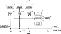
На Фиг.3 представлен еще один вариант выполнения системы 140 маркировки текучей среды. Система 140 маркировки текучей среды содержит множество источников 142, 144 и 146 маркера, множество регуляторов расхода текучей среды (РРТС) 148, 150 и 152, процессор 154, базу 156 данных, пользовательский интерфейс 158 и датчик 160. Текучая среда протекает по трубопроводу 162 от источника немаркированной текучей среды (не показана) к точке назначения (не показано) маркированной текучей среды.FIG. 3 illustrates yet another embodiment of a
Каждый из источников 142, 144 и 146 маркера аналогичен источнику 52 маркера. Процессор 154 аналогичен процессору 56. Маркер (не показан) в каждом из источников 142, 144 и 146 маркера аналогичен маркеру, описываемому выше. Пользовательский интерфейс 158 является клавиатурой, микрофоном, громкоговорителем, дисплеем, сенсорным экраном, сигнализационным указателем или их комбинацией, посредством которых пользователь обеспечивает соединение с процессором 154. При неисправности системы 140 маркировки текучей среды (например, если не срабатывают один или более элементов), то сигнальное устройство (не показано) формирует звуковой или видимый сигнал, чтобы сообщить о неисправности пользователю. Датчик 160 аналогичен датчику 58.Each of
База 156 данных содержит данные, соответствующие работе каждого из регуляторов 148, 150 и 152 расхода текучей среды, данные, соответствующие типу каждого маркера, молекулярной структуре каждого маркера, количеству каждого маркера, который вводят в протекающую текучую среду, отношению маркер/текучая среда для каждого из маркеров в месте назначения маркированной текучей среды, типу датчика 160, множеству значений выходного сигнала датчика 160, типу протекающей текучей среды, коду маркера и т.п. Каждый из регуляторов 148, 150 и 152 расхода текучей среды аналогичен регулятору 54 расхода текучей среды.The
Входные отверстия (не показаны) регуляторов 148, 150 и 152 расхода текучей среды соединены с источниками 142, 144 и 146 маркера соответственно. Выходные отверстия (не показаны) регуляторов 148, 150 и 152 расхода текучей среды соединены с трубопроводом 162 в пунктах 164, 166 и 168 соответственно введения маркера. Либо регуляторы 148, 150 и 152 расхода текучей среды могут быть соединены с трубопроводом 162 в едином пункте (не показан) введения маркера. Процессор 154 соединен с регуляторами 148, 150 и 152 расхода текучей среды, базой данных 156, пользовательским интерфейсом 158 и датчиком 160.The inlets (not shown) of the
Датчик 160 измеряет по меньшей мере одно свойство текучей среды, протекающей по трубопроводу 162, в точке 170 и направляет сигнал, соответствующий этому измеренному свойству, в процессор 154. Пользователь вводит данные, соответствующие типу маркируемой текучей среды, маркерный код и т.п. по пользовательскому интерфейсу 158. Маркерный код содержит сведения, характеризующие тип маркеров, молекулярную структуру каждого из маркеров, выбранную комбинацию маркеров, выбранные концентрации маркера для этих маркеров, время и дату маркировки, географическое местоположение маркировки, тип и источник немаркированной текучей среды и т.п. Маркерный код может быть выполнен в виде буквенно-цифрового шифра, штрихкода и т.п.The
Процессор 154 производит выборку данных маркера из базы 156 данных согласно данным, принятым от пользовательского интерфейса 158, и согласно сигналу, принятому от датчика 160. База 156 данных может быть заменена запоминающим устройством (не показано) в процессоре 154, при этом процессор 154 производит выборку этих данных маркера из указанного запоминающего устройства.The
Процессор 154 управляет работой каждого из регуляторов 148, 150 и 152 расхода текучей среды согласно выходному сигналу датчика 160, данным, принятым из пользовательского интерфейса 158, и маркерным данным, полученным из базы 156 данных.A
Каждый из регуляторов 148, 150 и 152 расхода текучей среды действует согласно сигналу, принимаемому от процессора 154, и доставляет заданное количество каждого маркера от каждого из источников 142, 144 и 146 выведения маркера соответственно в протекающую текучую среду в точках 164, 166 и 168 введения маркера соответственно. При этом, когда полный объем текучей среды будет передан от источника немаркированной текучей среды к месту назначения маркированной текучей среды, маркированная текучая среда в месте назначения маркированной текучей среды будет содержать каждый из маркеров источников 142, 144 и 146 маркера, с соответствующей концентрацией маркера. При этом система 140 маркирования выполнена с возможностью маркирования текучей среды разными маркерами с разными концентрациями маркера, тем самым обеспечивая возможность обнаружения поддельной текучей среды с большей вероятностью по сравнению с системой 50 маркирования текучей среды.Each of the
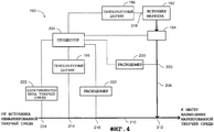
На Фиг.4 представлена система 190 маркировки текучей среды, которая содержит источник 192 маркера, регулятор 194 расхода текучей среды, датчики 196 и 198 температуры, расходомеры 200 и 202, идентификатор 222 типа текучей среды и процессор 204. Источник 192 маркера аналогичен источнику 52 маркера, и маркер (не показан) в источнике 192 маркера аналогичен указанному выше маркеру. Регулятор 194 расхода текучей среды аналогичен регулятору 54 расхода текучей среды. Идентификатор 222 типа текучей среды является устройством, которое идентифицирует тип текучей среды путем измерения по меньшей мере одного свойства текучей среды - плотности, вязкости, диэлектрической постоянной. Например, идентификатор 222 типа текучей среды может быть выполнен в виде ареометра, вискозиметра. Процессор 204 аналогичен процессору 56.4, a
Процессор 204 соединен с регулятором 194 расхода текучей среды, температурными датчиками 196 и 198, идентификатором 222 типа текучей среды и с расходомерами 200 и 202. Текучая среда протекает в трубопроводе 2100 от источника немаркированной текучей среды (не показан) к месту назначения маркированной текучей среды (не показано). Входное отверстие (не показано) регулятора 194 расхода текучей среды соединено с источником 192 маркера. Выходное отверстие (не показано) регулятора 194 расхода текучей среды соединено с трубопроводом 210 в пункте 212 введения маркера на трубопроводе 210, через трубопровод 208. Расходомер 200 соединен с трубопроводом 208 в измерительном пункте 220. Температурный датчик 196 соединен с источником 192 маркера в измерительном пункте 218.The
Датчик 198 температуры и расходомер 202 измеряют температуру и расход текучей среды, которая протекает в трубопроводе 210, в измерительных пунктах 214 и 216 соответственно трубопровода 210. Идентификатор 222 типа текучей среды измеряет свойство текучей среды, которая протекает в трубопроводе 210, в измерительных пунктах 224 трубопровода 210. Расходомер 200 измеряет расход маркера, который проходит по трубопроводу 208, в измерительном пункте 220. Датчик 196 температуры измеряет температуру маркера в источнике 192 маркера, в измерительном пункте 218. Измерительные пункты 214, 224 и 216 могут совпадать. Измерительные точки 214, 224 и 216 расположены либо после точки 212 введения маркера, либо перед ним.The
Процессор 204 определяет тип текучей среды, которая протекает по трубопроводу 210, согласно сигналу, принимаемому из идентификатора 222 типа текучей среды. Процессор 204 управляет работой регулятора 194 расхода текучей среды согласно сигналам, принимаемым от датчиков 196 и 198 температуры и от расходомеров 200 и 202. Процессор 204 управляет работой регулятора 194 расхода текучей среды и тем самым расходом маркера в трубопроводе 208 согласно сигналу обратной связи, принимаемому от расходомера 200. Путем измерения температуры маркера в источнике 192 маркера и расхода маркера в трубопроводе 208, до смешения с протекающей текучей средой, процессор 204 может определить количество маркера, которое должно быть введено в протекающую текучую среду, точнее, чем процессор 56. Необходимо отметить, что система 190 маркировки текучей среды может действовать по меньшей мере с одним из датчиков 196 и 198 температуры, по меньшей мере с одним из расходомеров 200 и 202, или с любой их комбинацией.The
Нужная концентрация маркера в некоторых случаях может составлять 10 чмл и даже порядка 1 чмрд. Для применения точных количеств этих низких концентраций обычно необходимо разбавлять маркер перед его введением в немаркированную текучую среду. Разбавитель необязательно должен быть идентичен немаркированной текучей среде, необходимо, чтобы он соответствовал определенным критериям, позволяющим его ведение в немаркированную текучую среду, таким как рабочая совместимость и долговечность немаркированной текучей среды. Если разбавленный маркер заранее не приготовлен, то маркер в разных концентрациях можно разбавить на месте.The desired marker concentration in some cases can be 10 ppm or even about 1 ppm. To apply the exact amounts of these low concentrations, it is usually necessary to dilute the marker before it is introduced into the unlabelled fluid. The diluent does not have to be identical to an unlabelled fluid, it must be met by certain criteria that allow it to be introduced into an unlabelled fluid, such as working compatibility and durability of an unlabelled fluid. If a diluted marker is not prepared in advance, then the marker in different concentrations can be diluted in place.
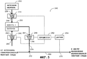
На Фиг.5 представлена выполненная и действующая система 240 маркировки текучей среды, которая содержит источник 242 маркера, регуляторы 244, 246 и 248, емкость 250 для разбавленного маркера, процессор 252 и датчик 254. Регулятор 244 расхода текучей среды имеет входное отверстие 256 и выходное отверстие 258. Регулятор 246 расхода текучей среды имеет входное отверстие 260 и выходное отверстие 262. Регулятор 248 расхода текучей среды имеет входное отверстие 264 и выходное отверстие 266. Каждый из регуляторов 244, 246 и 248 расхода текучей среды аналогичен регулятору 54. Процессор 252 аналогичен процессору 56. Датчик 254 аналогичен датчику 58.Figure 5 presents a completed and current system for marking a fluid medium, which contains a source of 242 markers,
Процессор 252 соединен с регуляторами 244, 246 и 248 расхода текучей среды и с датчиком 254. Источник 242 маркера соединен с входным отверстием 256. Емкость 250 для разбавленного маркера соединена с выходными отверстиями 258 и 262 и со входным отверстием 264.The
Текучая среда протекает в трубопроводе 268 от источника немаркированной текучей среды (не показан) к месту назначения (не показано) маркированной текучей среды. Входное отверстие 260 соединено с источником немаркированной текучей среды. Процессор 252 направляет сигнал в регулятор 246 расхода текучей среды, чтобы ввести заданное количество текучей среды из источника немаркированной текучей среды в емкость 250 для разбавленного маркера. Процессор 252 направляет сигнал в регулятор 244 расхода текучей среды, чтобы ввести заданное количество маркера из источника 242 маркера в емкость 250 для разбавленного маркера. Текучая среда и маркер смешиваются в емкости 250 разбавленного маркера, и теперь емкость 250 для разбавленного маркера содержит разбавленный маркер с первой концентрацией маркера.Fluid flows in a
Датчик 254 измеряет свойство текучей среды, которая протекает по трубопроводу 268, в измерительном пункте 270 трубопровода 268, и направляет сигнал, соответствующий измеренному свойству, в процессор 252. Процессор 252 управляет работой регулятора 248 расхода текучей среды, чтобы ввести выбранное количество разбавленного маркера из емкости 250 для разбавленного маркера в текучую среду, которая протекает по трубопроводу 268. Процессор 252 управляет работой регулятора 248 расхода текучей среды согласно сигналу, принимаемому от датчика 254. Регулятор 248 расхода текучей среды действует согласно сигналу, принимаемому от процессора 252, и вводит выбранное количество разбавленного маркера в текучую среду, которая протекает в трубопроводе 268, в пункте 272 введения маркера на трубопроводе 268.A
Разбавленный маркер протекает от выходного отверстия 266 к точке 272 введения маркера в трубопроводе 274. Разбавленный маркер, содержащий маркер с первой концентрацией маркера, смешивается с текучей средой, которая протекает в трубопроводе 268, и поэтому текучая среда после точки 272 введения маркера содержит маркер со второй концентрацией маркера.The diluted marker flows from the
Поскольку действие регулятора 248 расхода текучей среды в емкости 250 с разбавленным маркером является умножительным, вторая концентрация маркера меньше первой концентрации маркера на несколько порядков. Например, если первая концентрация маркера равна 3 чмл и расход в трубопроводе 274 составляет одну тысячную расхода в трубопроводе 268, то вторая концентрация маркера равна 3 чмрд (т.е. одной тысячной от первой концентрации маркера). Поэтому система 240 маркировки текучей среды обеспечивает возможность маркировки существенно меньших концентраций, чем система 50 маркировки текучей среды.Since the action of the
Нужно отметить, что дополнительные датчики, аналогичные датчику 254, можно использовать для измерения свойств текучей среды или маркера в другом месте, а не в системе 240 маркировки. Дополнительные датчики могут размещаться между источником немаркированной текучей среды и емкостью с разбавленным маркером, между источником маркера и емкостью с разбавленным маркером, между емкостью с разбавленным маркером и точкой введения маркера, в источнике маркера. Каждый из дополнительных датчиков соединен с процессором. Свойства текучей среды и маркера измеряют в этих дополнительных местах. При этом первая концентрация маркера и вторая концентрация маркера могут регулироваться с большей точностью.It should be noted that additional sensors, similar to the
Система 240 маркировки текучей среды может действовать без регуляторов 244 и 246 расхода текучей среды, и в этом случае емкость 250 для разбавленного маркера заполняется заранее разбавителем и маркером в нужной концентрации. Этот разбавитель является текучей средой, которая совместима с текучей средой, протекающей в трубопроводе 268. Например, если по трубопроводу 268 протекает бензин, то бензин или дизельное топливо можно использовать для разбавления маркера из источника 242 маркера. Либо регулятор 246 расхода текучей среды может быть насосом, чтобы перекачивать разбавитель из емкости (не показана) с разбавителем или из трубопровода, по которому протекает разбавитель, в емкость 250 для разбавленного маркера.The
Либо несколько разных маркеров разбавляют разбавителем в емкости для разбавленного маркера. Маркеры можно разбавлять вручную или автоматически. Если маркеры разбавляются автоматически, то несколько источников маркера (не показаны) соединены со входным отверстием насоса маркера (не показан) посредством клапанов (не показаны), аналогичным клапану 108. Входное отверстие каждого из клапанов соединено с соответствующим источником маркера, выходные отверстия клапанов соединены со входным отверстием насоса маркера, и выходное отверстие насоса маркера соединено с емкостью с разбавленным маркером. Каждый из клапанов и каждый из насосов маркера соединены с процессором.Or several different markers are diluted with diluent in a diluted marker container. Markers can be diluted manually or automatically. If the markers are automatically diluted, then several marker sources (not shown) are connected to the marker pump inlet (not shown) by valves (not shown) similar to
Либо входное отверстие регулятора 248 расхода текучей среды может быть в любое заданное время соединено с другой емкостью для разбавленного маркера. Когда регулятор 248 расхода текучей среды является насосом, входное отверстие насоса соединено с несколькими емкостями для разбавленного маркера через несколько клапанов, аналогичных клапану 108, предназначенных для каждой емкости для разбавленного маркера.Or, the inlet to the
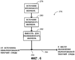
На Фиг.6 представлена система 276 маркировки текучей среды, которая содержит источник 278 вторичного маркера, источник 280 первичного маркера, и емкость 282 для разбавленного маркера. Текучая среда протекает по трубопроводу 284 от источника (не показан) немаркированной текучей среды к месту назначения (не показано) с маркированной текучей средой. Первичный источник 280 маркера соединен с источником 278 вторичного маркера и с емкостью 282 для разбавленного маркера. Емкость 282 для разбавленного маркера соединена с трубопроводом 284 в точке 286 введения маркера на трубопроводе 284.FIG. 6 illustrates a
Источник 278 вторичного маркера содержит вторичный маркер, и первичный источник 280 содержит первичный маркер. И вторичный, и первичный маркеры аналогичны маркеру, описанному выше. Емкость 282 для разбавленного маркера содержит разбавитель, аналогичный разбавителю, описываемому выше. Источник 278 вторичного маркера может содержать разные типы вторичных маркеров, и источник 280 вторичного маркера может содержать разные типы первичных маркеров.
Молекулярные структуры вторичного маркера и первичного маркера разные, что может заключаться в атомных элементах разных маркеров, чтобы можно было определенно идентифицировать каждый маркер с помощью детектора маркера. Вторичный маркер разбавляется в первичном маркере. При этом первичный маркер в источнике 280 для первичного маркера содержит вторичный маркер с существенно более низкой концентрацией. Содержание источника 280 первичного маркера (т.е. вторичного маркера, разбавленного в первичном маркере) далее разбавляется в разбавителе емкости 282 разбавленного маркера. Концентрация первичного маркера в маркерном растворе емкости 282 разбавленного маркера обозначена как С1Р, и концентрация вторичного маркера в маркерном растворе емкости 282 разбавленного маркера обозначена как С1S, гдеThe molecular structures of the secondary marker and the primary marker are different, which may be in the atomic elements of different markers, so that each marker can be definitely identified using a marker detector. The secondary marker is diluted in the primary marker. In this case, the primary marker in the
Маркерный раствор из емкости 282 с разбавленным маркером вводят в текучую среду, идущую по трубопроводу 284, в точке 286 введения маркера. Маркерный раствор разжижается в текучей среде в пункте маркированной текучей среды при концентрации CMS. Концентрация первичного маркера в пункте маркированной текучей среды обозначена как С2Р, и концентрация вторичного маркера в пункте маркированной текучей среды обозначена как С2S, причемA marker solution from a diluted
иand
поэтомуso
иand
Концентрация вторичного маркера в пункте маркировки текучей среды С2S настолько низкая, что детектор маркера, аналогичный детектору 302 маркера, обычно не в состоянии обнаруживать наличие вторичного маркера в пункте маркировки текучей среды. Но наличие вторичного маркера в пункте маркировки текучей среды можно обнаруживать более точными и более длительными и трудоемкими способами, например за счет увеличения концентрации проверяемой текучей среды, воспламеняя пробу проверяемой текучей среды перед испытанием на устранение некоторых веществ текучей среды, и т.п. Поэтому количество вторичного маркера выбирают существенно более низким, чем количество первичного маркера, в результате чего наличие вторичного маркера в текучей среде невозможно обнаружить (например, анализатором флуоресценции рентгеновских лучей) без повышения концентрации вторичного маркера в текучей среде. Эта конфигурация повышает защищенность против легкой идентификации маркеров, введенных в результате незаконных действий, направленных на имитацию маркера для поддельного воспроизведения маркера и введения его в поддельную текучую среду.The concentration of the secondary marker at the C 2S fluid marking point is so low that a marker detector, similar to the marker detector 302, is usually not able to detect the presence of a secondary marker at the fluid marking point. But the presence of a secondary marker at the fluid labeling point can be detected by more accurate and longer and more laborious methods, for example, by increasing the concentration of the fluid being tested, igniting the sample of the fluid being tested before testing for the removal of certain fluid substances, etc. Therefore, the amount of the secondary marker is chosen to be substantially lower than the amount of the primary marker, as a result of which the presence of the secondary marker in the fluid cannot be detected (for example, by an X-ray fluorescence analyzer) without increasing the concentration of the secondary marker in the fluid. This configuration increases security against the easy identification of markers introduced as a result of illegal actions aimed at simulating a marker to fake a marker and inject it into a fake fluid.
Необходимо отметить, что при низких концентрациях обнаружение самого наличия вторичного маркера возможно, но обычно невозможно определить концентрацию вторичного маркера в маркированной текучей среде.It should be noted that at low concentrations, the detection of the presence of a secondary marker is possible, but it is usually not possible to determine the concentration of a secondary marker in a marked fluid.
Вторичный маркер служит в качестве метки для первичного маркера. Если проверяемая текучая среда является поддельной текучей средой, то она содержит маркер, идентичный первоначальному первичному маркеру с правильной концентрацией маркера, и не содержит метку (т.е. вторичный маркер), то система 300 проверки текучей среды (Фиг.6) все же может определить, что данная проверяемая текучая среда является подлинной. Но система обнаружения (не показана) обнаружит отсутствие вторичного маркера в проверяемой текучей среде и определит, что проверяемая текучая среда не является подлинной.The secondary marker serves as a label for the primary marker. If the fluid being tested is a fake fluid, then it contains a marker identical to the original primary marker with the correct marker concentration and does not contain a label (i.e. a secondary marker), then the fluid verification system 300 (FIG. 6) may still determine that the fluid being tested is genuine. But a detection system (not shown) will detect the absence of a secondary marker in the fluid being tested and determine that the fluid being tested is not genuine.
Код маркера может также содержать информацию, характеризующую вторичный маркер. Маркерный раствор можно приготовить либо вручную, либо автоматически, используя комбинацию клапанов (не показана) и насосов (не показаны), соединенных с источником вторичного маркера, источником первичного маркера и с емкостью для разбавленного маркера.The marker code may also contain information characterizing the secondary marker. A marker solution can be prepared either manually or automatically, using a combination of valves (not shown) and pumps (not shown) connected to a secondary marker source, primary marker source, and a diluted marker container.
Необходимо отметить, что источник 280 первичного маркера может содержать несколько разных вторичных маркеров, и при этом поддельной текучей среде будет труднее пройти проверку. Система 276 маркировки текучей среды может содержать несколько источников вторичного маркера, аналогичных источнику 278 вторичного маркера, несколько источников первичного маркера, аналогичных источнику 280 первичного маркера, несколько источников разбавленного маркера, аналогичных источнику 282 для разбавленного маркера.It should be noted that the
Например, вторичный маркер - йодид этила, и первичный маркер - тетрабромэтан, разбавлены в маркерном растворе емкости 282 для разбавленного маркера. С1Р составляет 2% и С1S составляет 300 чмл. Когда маркерный раствор вводят в текучую среду, протекающую по трубопроводу 284, концентрация первичного маркера в месте назначения маркированной текучей среды С2Р составляет 3 чмл, и концентрация вторичного маркера в месте назначения маркированной текучей среды С2S составляет 1 чмрд. Система проверки текучей среды, аналогичная системе 300 проверки текучей среды (Фиг.6), выполнена с возможностью обнаруживать наличие первичного маркера и измерять его концентрацию в маркированной текучей среде, но обычно она не в состоянии обнаружить наличие вторичного маркера в маркированной текучей среде. Но более точная система проверки текучей среды может обнаруживать наличие вторичного маркера в маркированной текучей среде.For example, a secondary marker, ethyl iodide, and a primary marker, tetrabromoethane, are diluted in a marker solution in a 282 tank for a diluted marker. C 1P is 2% and C 1S is 300 ppm. When the marker solution is introduced into the fluid flowing through
Если поддельная текучая среда содержит тетрабромэтан с концентрацией 3,1 чмл и не содержит йодид этила, то первая система проверки текучей среды, аналогичная системе 300 проверки текучей среды (Фиг.6), обычно определяет, что поддельная текучая среда является подлинной. Но если та же поддельная текучая среда проверятся более точной системой проверки текучей среды, то она определяет, что молекулы йодида этила отсутствуют в поддельной текучей среде и что поддельная текучая среда не является подлинной. Таким образом, путем маркировки текучей среды с помощью системы 276 маркировки текучей среды точность определения подлинности текучей среды повышается по сравнению с текучей средой, которая маркирована системой 50 маркировки текучей среды (Фиг.1).If the fake fluid contains 3.1 tml bromoethane and does not contain ethyl iodide, then the first fluid verification system, similar to the fluid verification system 300 (FIG. 6), typically determines that the fake fluid is genuine. But if the same fake fluid is verified by a more accurate fluid verification system, then it determines that ethyl iodide molecules are not present in the fake fluid and that the fake fluid is not genuine. Thus, by marking the fluid using the
На Фиг.7 представлена система 300 проверки текучей среды, которая содержит детектор 302 маркера, процессор 304, базу данных 306 и пользовательский интерфейс 308.7 illustrates a
Детектор 302 маркера является устройством, выполненным с возможностью обнаруживать наличие, отсутствие, тип маркера в текучей среде и измерять свойства этого маркера в текучей среде. Детектор 302 маркера может измерять по меньшей мере одно свойство маркера, такое как уровень излучения, длина волны поглощаемого или испускаемого светового излучения, уровень атомной энергии, частота атомных колебаний.The marker detector 302 is a device configured to detect the presence, absence, type of marker in a fluid and measure the properties of this marker in a fluid. Marker detector 302 can measure at least one property of the marker, such as radiation level, wavelength of absorbed or emitted light radiation, atomic energy level, atomic frequency.
Детектор 302 маркера может быть спектрометром, анализатором флуоресценции рентгеновских лучей, газовым хроматографом, фотоприемником, радиационным детектором, устройством визуализации с помощью магнитного резонанса, ядерного магнитного резонанса и т.п. Пользовательский интерфейс аналогичен пользовательскому интерфейсу 158. Процессор 304 аналогичен процессору 56. База данных 306 содержит данные о разных кодах маркера (т.е. данные о маркерах).The marker detector 302 may be a spectrometer, an X-ray fluorescence analyzer, a gas chromatograph, a photodetector, a radiation detector, a magnetic resonance imaging device, nuclear magnetic resonance, and the like. The user interface is similar to
Процессор 304 соединен с детектором 302 маркера, базой данных 306 и пользовательским интерфейсом 308. Пользователь вводит код маркера через пользовательский интерфейс 308, и пользовательский интерфейс 308 направляет данные о коде маркера в процессор 304. Этот код маркера аналогичен коду, описанному выше. Процессор 304 формирует сигнал для детектора 302 маркера для обнаружения наличия, отсутствия и типа маркера в текучей среде и для измерения свойств маркера в текучей среде. Детектор 302 маркера может либо проверить объем текучей среды, например, протекающей по трубопроводу, или проверить пробу текучей среды, взятую из объема текучей среды, например, пробу топлива, взятую из газгольдера. Детектор 302 маркера проверяет текучую среду и направляет данные о результате проверки в процессор 304. Процессор 304 производит выборку маркерных данных из базы данных 306 согласно данным, принятым от пользовательского интерфейса 308. База данных 306 может быть заменена запоминающим устройством (не показано) в процессоре 304, процессор 304 производит выборку данных маркера из этого запоминающего устройства.A
Детектор 302 маркера устанавливает наличие маркера в текучей среде и измеряет концентрацию маркера в этой текучей среде. Процессор 304 производит выборку данных о маркере в отношении тождества маркера и заданной концентрации маркера из базы данных 306 согласно коду маркера. Процессор 304 сравнивает данные детектора маркера с данными маркера. Если информация о типе данных, содержащаяся в данных детектора маркера и в данных маркера, совпадает и концентрация маркера, указанная данными детектора маркера, равна в допустимых пределах погрешности концентрации маркера, указанной данными маркера, то процессор 304 определяет, что проверяемая текучая среда является подлинной.Marker detector 302 detects the presence of a marker in the fluid and measures the concentration of the marker in the fluid. The
Если информация о типе маркера, содержащаяся в данных детектора маркера и в данных маркера, не совпадает, или если концентрация маркера, указанная данными детектора маркера, имеет отклонение свыше приемлемого предела погрешности относительно концентрации маркера, указанной данными маркера, то процессор 304 определяет, что проверяемая текучая среда не является подлинной. Процессор 304 формирует сигнал подлинности проверяемой текучей среды для пользовательского интерфейса 308, и пользовательский интерфейс 308 создает выходной сигнал согласно сигналу, принимаемому от процессора 304.If the marker type information contained in the marker detector data and the marker data does not match, or if the marker concentration indicated by the marker detector data deviates from an acceptable margin of error with respect to the marker concentration indicated by the marker data, then the
Например, код маркера содержит информацию о нефтеперерабатывающем заводе, который является источником текучей среды. Процессор 304 обрабатывает данные детектора маркера, принимаемые от детектора 302 маркера, и данные маркера, взятые из базы данных, и определяет, соответствует ли источник проверяемой текучей среды информации о коде маркера, характеризующем текучую среду, происходящую из этого нефтеперерабатывающего завода.For example, the marker code contains information about the refinery, which is the source of the fluid. The
Либо процессор 304 содержит данные маркера в отношении единого кода маркера, и система 300 проверки текучей среды не имеет базы данных 306.Or,
Процессор 304 сравнивает данные детектора маркера, принимаемые от детектора маркера 302, с данными маркера, запомненными в процессоре 304, и определяет подлинность или поддельность проверяемой текучей среды. Система проверки текучей среды, аналогичная системе 300 проверки текучей среды, может быть установлена, например, в автомобиле, чтобы определить, заправлен ли бак автомобиля определенным сортом топлива.The
На Фиг.8 представлена система 330 проверки текучей среды, которая содержит несколько идентификаторов 332, 334 и 336, интерфейс 338 связи, базу данных 340 и шину 342. Интерфейс 338 связи соединен с базой данных 340 и с шиной 342. Идентификаторы 332, 334 и 334 источника текучей среды соединены с шиной 342.FIG. 8 illustrates a
Шина 342 является либо линией радиосвязи (например, спутниковой связью, сотовой сетью связи, оптикой в открытом космосе и т.п.), проводным соединением или их комбинацией. Каждый из идентификаторов 332, 334 и 336 и интерфейс 338 связи может быть соединен с шиной 342 либо по линии радиосвязи, проводной связью или с помощью их комбинации.
Идентификатор 332 источника текучей среды содержит детектор 344 маркера, процессор 336, пользовательский интерфейс 348 и интерфейс 350 связи. Детектор 344 маркера и пользовательский интерфейс 348 аналогичны детектору 302 маркера и пользовательскому интерфейсу 308 соответственно. База данных 340 аналогична базе данных 306. Процессор 346 аналогичен процессору 56. Процессор 346 соединен с детектором 344 маркера, пользовательским интерфейсом 348 и с интерфейсом связи 350. Интерфейс связи соединен с шиной 342.The
Приводимое ниже описание идентификатора 332 источника текучей среды также относится и к идентификаторам 334 и 336 источника текучей среды. Пользователь вводит данные о типе текучей среды №1, код маркера и т.п. по пользовательскому интерфейсу 348, и пользовательский интерфейс 348 направляет данные в процессор 346. Процессор 346 направляет сигнал в детектор 344 маркера, чтобы проверить текучую среду №1. Детектор 344 маркера проверяет текучую среду №1 и направляет данные о результате испытания в процессор 346.The following description of the
Процессор 346 устанавливает связь с базой данных 340 по интерфейсам 350 и 338 связи и шину 342 и извлекает данные из базы данных 340 согласно данным, принятым от пользовательского интерфейса 348. Процессор 346 обрабатывает данные, принятые от детектора 344 маркера, данные, принятые от пользовательского интерфейса 348, и данные, извлеченные из базы данных 340, определяет, является ли текучая среда №1 подлинной или нет, и направляет соответствующий сигнал в пользовательский интерфейс 348. Пользовательский интерфейс 348 формирует выходной сигнал в соответствии с сигналом, принятым от процессора 346. Необходимо отметить, что поскольку база данных в идентификаторах 332, 334 и 336 отсутствует, поэтому идентификаторы 332, 334 и 336 источника текучей среды могут быть переносными и компактными, тем самым облегчая определение подлинности текучей среды на месте. Система 330 проверки текучей среды может использоваться, например, для контроля топлива на разных автозаправочных станциях, в разных хранилищах, в каждой автозаправочной станции, на распределительных пунктах нефтезаводов.The
На Фиг.9 представлена последовательность способа маркирования текучей среды согласно еще одному варианту осуществления изобретения. На этапе 370 текучая среда протекает от источника немаркированной текучей среды к месту назначения маркированной текучей среды. На Фиг.1 текучая среда протекает по трубопроводу 64 от источника немаркированной текучей среды к месту назначения маркированной текучей среды либо с помощью насоса, либо под воздействием силы тяжести.Figure 9 presents the sequence of the method of marking a fluid according to another variant embodiment of the invention. At
На этапе 372 (Фиг.9) измеряют свойство текучей среды, которая проходит от источника немаркированной текучей среды к месту назначения маркированной текучей среды. На Фиг.1 датчик 58 измеряет расход текучей среды, которая протекает по трубопроводу 64 и направляет сигнал о расходе в процессор 56.At step 372 (FIG. 9), a property of the fluid that extends from the source of the unmarked fluid to the destination of the marked fluid is measured. 1, a sensor 58 measures the flow rate of a fluid that flows through conduit 64 and sends a flow signal to a processor 56.
На этапе 374 определяют количество маркера, который нужно ввести в текущую текучую среду согласно измеренному свойству. На Фиг.1 процессор 56 определяет количество маркера, который нужно ввести в текучую среду в пункте 66 введения маркера согласно сигналу о расходе и с помощью справочной таблицы, запомненной в процессоре 56. Например, если регулятор 54 расхода текучей среды является насосом переменной производительности, то процессор 56 определяет режим перекачки для регулятора 54 расхода текучей среды.At 374, the amount of marker to be introduced into the current fluid is determined according to the measured property. 1, processor 56 determines the amount of marker to be introduced into the fluid in step 66 of introducing the marker according to the flow signal and using the lookup table stored in the processor 56. For example, if the fluid flow controller 54 is a variable displacement pump, then the processor 56 determines a pumping mode for the fluid flow controller 54.
На этапе 376 определенное количество маркера вводят в проходящую текучую среду, при этом маркируя ее. На Фиг.1 процессор 56 направляет сигнал в регулятор 54 расхода текучей среды, чтобы управлять работой регулятора 54 расхода текучей среды, в результате чего регулятор 54 расхода текучей среды вводит определенное количество маркера в протекающую текучую среду. Если регулятор 54 расхода текучей среды является насосом переменной производительности, то он работает в заданном режиме перекачки, чтобы ввести заданное количество маркера в пункте 66 введения маркера в течение данной длительности времени.At step 376, a certain amount of marker is introduced into the passing fluid, while labeling it. 1, a processor 56 sends a signal to a fluid flow regulator 54 to control the operation of a fluid flow regulator 54, whereby a fluid flow regulator 54 introduces a certain amount of marker into the flowing fluid. If the fluid flow controller 54 is a variable displacement pump, then it operates in a predetermined pumping mode to enter a predetermined amount of marker in paragraph 66 of the introduction of the marker for a given length of time.
На Фиг.10 представлен способ проверки текучей среды согласно еще одному варианту осуществления изобретения. На этапе 400 определяют концентрацию первичного маркера в текучей среде. На Фиг.7 детектор 302 маркера определяет концентрацию первичного маркера в проверяемой текучей среде. Это первичный маркер мог быть введен в проверяемую текучую среду с помощью системы маркирования текучей среды, аналогичной системе 276 маркирования текучей среды (Фиг.6). Необходимо отметить, что система 276 маркирования текучей среды может вводить несколько разных первичных маркеров, и поэтому детектор 302 маркера определяет концентрацию нескольких разных первичных маркеров.Figure 10 presents a method of checking fluid according to another variant embodiment of the invention. At
На этапе 402 определенную концентрацию сравнивают с заданной концентрацией. На Фиг.7 процессор 304 принимает данные детектора маркера от детектора 302 маркера, причем эти данные детектора маркера содержат информацию о концентрации первичного маркера в проверяемой текучей среде. Процессор 304 извлекает данные о маркере из базы данных 304 согласно данным о коде маркера, которые пользователь ввел в пользовательский интерфейс 308. Процессор 304 сравнивает заданную концентрацию, указанную в данных детектора маркера, с заданной концентрацией маркера, указанной в данных маркера.At 402, a specific concentration is compared with a predetermined concentration. 7, a
На этапе 404 сначала определяют первую подлинность текучей среды согласно результатам сравнения. На Фиг.6, если определенная концентрация равна в пределах приемлемой погрешности заданной концентрации, то процессор 304 определяет, что проверяемая текучая среда подлинная. Если данная текучая среда определена как подлинная, то способ переходит к этапу 406. Поскольку этап 405 относительно дорогостоящий и занимает много времени, то его выполняют только в том случае, если результат этапа 404 сомнителен. Если определено, что текучая среда не является подлинной, то способ завершается на этапе 404.At 404, a first fluid authenticity is first determined according to the comparison results. In FIG. 6, if the determined concentration is within the acceptable error of the given concentration, then the
На этапе 406 концентрацию вторичного маркера в текучей среде повышают, если первая подлинность положительная. Концентрацию необходимо повысить по той причине, что концентрация вторичного маркера гораздо ниже концентрации первичного маркера, чтобы скрыть наличие вторичного маркера, и при этом первичный маркер обнаруживается детектором 302 (Фиг.7). Концентрацию вторичного маркера в текучей среде можно повысить такими способами, как сжигание текучей среды, фильтрация веществ текучей среды, проведение соответствующей химической реакции текучей среды с несколькими химическими веществами и т.п.At 406, the concentration of the secondary marker in the fluid is increased if the first authenticity is positive. The concentration must be increased for the reason that the concentration of the secondary marker is much lower than the concentration of the primary marker in order to hide the presence of the secondary marker, and the primary marker is detected by the detector 302 (FIG. 7). The concentration of a secondary marker in a fluid can be increased by methods such as burning a fluid, filtering a fluid, conducting an appropriate chemical reaction of a fluid with several chemicals, and the like.
На этапе 408 определяют наличие вторичного маркера в текучей среде. Вторичный маркер мог быть введен в текучую среду системой маркировки текучей среды, аналогичной системе 276 маркирования текучей среды (Фиг.6). Наличие вторичного маркера в проверяемой текучей среде определяется способами, которые описываются выше в связи с Фиг.6 (этап 410). Необходимо отметить, что система 276 маркировки текучей среды выполнена с возможностью введения разных вторичных маркеров в текучую среду, и поэтому на этапе 408 определяют наличие нескольких разных вторичных маркеров.At
Claims (69)
Applications Claiming Priority (2)
| Application Number | Priority Date | Filing Date | Title |
|---|---|---|---|
| US29591001P | 2001-06-04 | 2001-06-04 | |
| US60/295,910 | 2001-06-04 |
Publications (2)
| Publication Number | Publication Date |
|---|---|
| RU2003135224A RU2003135224A (en) | 2005-04-10 |
| RU2302000C2 true RU2302000C2 (en) | 2007-06-27 |
Family
ID=23139737
Family Applications (1)
| Application Number | Title | Priority Date | Filing Date |
|---|---|---|---|
| RU2003135224/28A RU2302000C2 (en) | 2001-06-04 | 2002-06-03 | Mode and a system of marking and definition of identity of liquid hydrocarbons |
Country Status (13)
| Country | Link |
|---|---|
| US (1) | US8158432B2 (en) |
| EP (1) | EP1392146B1 (en) |
| CN (1) | CN100573153C (en) |
| BR (1) | BR0210178A (en) |
| CA (1) | CA2446693C (en) |
| CO (1) | CO5650187A2 (en) |
| CR (1) | CR7175A (en) |
| EC (1) | ECSP034856A (en) |
| IL (1) | IL158679A0 (en) |
| MX (2) | MXPA01011530A (en) |
| PT (1) | PT1392146T (en) |
| RU (1) | RU2302000C2 (en) |
| WO (1) | WO2002098199A2 (en) |
Cited By (8)
| Publication number | Priority date | Publication date | Assignee | Title |
|---|---|---|---|---|
| RU2368645C2 (en) * | 2007-09-27 | 2009-09-27 | Государственное образовательное учреждение высшего профессионального образования "Казанский государственный университет им. В.И. Ульянова-Ленина" (ГОУ ВПО КГУ) | Identification method of marked oil products |
| RU2574021C1 (en) * | 2014-10-28 | 2016-01-27 | Общество с ограниченной ответственностью "ВОРМХОЛС Внедрение" | Fluorescent indicator for labelling oil and oil products and method of labelling oil and oil products |
| RU2683644C2 (en) * | 2016-03-02 | 2019-04-01 | Этикон, Инк. | Apparatus and method for analysing biological indicators |
| RU2724879C1 (en) * | 2019-10-08 | 2020-06-26 | Виталий Юрьевич Федоренко | Marker for fluid medium, fluid medium marking method and fluid medium identification method |
| US11390901B2 (en) | 2016-03-02 | 2022-07-19 | Asp Global Manufacturing Gmbh | Apparatus and method for analyzing biological indicators |
| US11660365B2 (en) | 2016-03-02 | 2023-05-30 | Asp Global Manufacturing Gmbh | Apparatus and method for sterilizing medical devices |
| US11766495B2 (en) | 2016-03-02 | 2023-09-26 | Asp Global Manufacturing Gmbh | Method of sterilizing medical devices, analyzing biological indicators, and linking medical device sterilization equipment |
| RU2809678C1 (en) * | 2020-11-19 | 2023-12-14 | ФЛОДЖИСТИКС, ЭлПи | Certified vapor collection |
Families Citing this family (39)
| Publication number | Priority date | Publication date | Assignee | Title |
|---|---|---|---|---|
| US20070157510A1 (en) * | 2004-01-14 | 2007-07-12 | Yair Grof | Fuel additive comprising an alkyl halide |
| US8346491B2 (en) * | 2007-02-23 | 2013-01-01 | Expro Meters, Inc. | Sonar-based flow meter operable to provide product identification |
| US7627397B2 (en) * | 2007-09-28 | 2009-12-01 | Rockwell Automation Technologies, Inc. | Material-sensitive routing for shared conduit systems |
| US8690553B2 (en) * | 2008-02-04 | 2014-04-08 | Illinois Tool Works Inc. | Service pack tandem pump |
| US8592213B2 (en) * | 2008-10-03 | 2013-11-26 | Authentix, Inc. | Marking fuel for authentication using quantitative and binary markers |
| GB0901658D0 (en) | 2009-02-03 | 2009-03-11 | Johnson Matthey Plc | Methods of measuring fluorescence in liquids |
| EP2483681A1 (en) * | 2009-09-30 | 2012-08-08 | Authentix, Inc. | Detection of markers in pressurized hydrocarbon fluids |
| US9995681B2 (en) * | 2010-09-28 | 2018-06-12 | Authentix, Inc. | Determining the quantity of a taggant in a liquid sample |
| RU2479036C1 (en) * | 2011-09-09 | 2013-04-10 | Пильцов Сергей Сергеевич | Method to recognise and identify batches of commercial petrols |
| US9423392B1 (en) * | 2011-10-10 | 2016-08-23 | The Boeing Company | Methods and systems for indicating and determining fuel properties |
| US8710476B2 (en) * | 2011-11-03 | 2014-04-29 | Elwha Llc | Systems, devices, methods, and compositions including fluidized x-ray shielding compositions |
| US9412476B2 (en) | 2011-11-03 | 2016-08-09 | Elwha Llc | Systems, devices, methods, and compositions including fluidized x-ray shielding compositions |
| US9006694B2 (en) * | 2011-11-03 | 2015-04-14 | Elwha Llc | Systems, devices, methods, and compositions including fluidized x-ray shielding compositions |
| CN102620782A (en) * | 2012-03-22 | 2012-08-01 | 沈阳工程学院 | Detection device for pipeline flow signals |
| MX2014012594A (en) * | 2012-04-16 | 2015-02-24 | Weatherford Lamb | Method and apparatus for monitoring a downhole tool. |
| US9291609B2 (en) | 2012-04-30 | 2016-03-22 | Ut-Battelle, Llc | Sensor system for fuel transport vehicle |
| WO2014022794A2 (en) | 2012-08-03 | 2014-02-06 | Conocophillips Company | Petroleum-fluid property prediction from gas chromatographic analysis of rock extracts or fluid samples |
| ES2593303T3 (en) | 2012-10-23 | 2016-12-07 | Koc Universitesi | A procedure and an apparatus for the detection of a fluid marking material |
| KR20160003716A (en) | 2013-04-22 | 2016-01-11 | 바스프 에스이 | Seal compatibility additive to improve fluoropolymer seal compatibility of lubricant compositions |
| US10066186B2 (en) | 2013-04-22 | 2018-09-04 | Basf Se | Lubricating oil compositions containing a halide seal compatibility additive and a second seal compatibility additive |
| TWI591338B (en) * | 2013-05-02 | 2017-07-11 | 羅門哈斯公司 | Analytical method for detecting fuel markers |
| TWI591339B (en) * | 2013-05-02 | 2017-07-11 | 羅門哈斯公司 | Analytical method for detecting fuel markers |
| US20140350736A1 (en) * | 2013-05-24 | 2014-11-27 | Remote Monitoring Systems, LLC | Fluid density valve access system |
| US11699196B2 (en) * | 2014-06-09 | 2023-07-11 | Sicpa Holding Sa | Creating secure data in an oil and gas supply chain |
| WO2016010494A1 (en) | 2014-07-17 | 2016-01-21 | Kuantag Nanoteknolojiler Geliştirme Ve Üretim A.Ş. | A fluorescent substance detection system |
| JP6869950B2 (en) | 2015-04-02 | 2021-05-12 | ソレック ニュークリア リサーチ センター | Systems and methods for reading X-ray fluorescent labels |
| US20160371704A1 (en) | 2015-06-18 | 2016-12-22 | Kuantag Nanoteknolojiler Gelistirme Ve Uretim A.S. | Integrated fuel tracking system |
| US10365239B2 (en) | 2016-02-15 | 2019-07-30 | Exxonmobil Research And Engineering Company | Method and system for in-situ identification of working fluids |
| WO2017142678A1 (en) * | 2016-02-15 | 2017-08-24 | Exxonmobil Research And Engineering Company | Systems and methods for authenticating working fluids |
| CN106526022B (en) * | 2016-11-09 | 2019-04-16 | 通标标准技术服务(上海)有限公司 | Whether diesel oil leaks into the method in lubricating oil in a kind of detection diesel pump |
| RU2726778C1 (en) * | 2017-02-03 | 2020-07-15 | Ресман Ас | Pumping target indicator with online sensor |
| US11262298B2 (en) * | 2018-08-30 | 2022-03-01 | Caterpillar Inc. | System and method for determining fluid origin |
| CN110850064B (en) * | 2019-12-03 | 2021-12-03 | 安徽省(水利部淮河水利委员会)水利科学研究院(安徽省水利工程质量检测中心站) | Method for detecting new and old water flowing on slope surface and in soil |
| WO2021110526A1 (en) | 2019-12-03 | 2021-06-10 | Sicpa Holding Sa | Method of marking a petroleum hydrocarbon |
| JP6947463B1 (en) * | 2020-04-08 | 2021-10-13 | ビーエルテック株式会社 | Flow analyzer and flow analysis method |
| US11988577B2 (en) | 2020-11-19 | 2024-05-21 | Flogistix, Lp | Certified vapor recovery |
| CO2021011871A1 (en) * | 2021-09-10 | 2021-09-30 | Blandon Cristian Felipe Ocampo | Intelligent optical tracer system, method and device that delivers a phosphorescent or fluorescent fluid to compute flow velocity |
| CA3264756A1 (en) | 2022-08-15 | 2024-02-22 | Sicpa Holding Sa | Method and apparatus for marking a liquid hydrocarbon in a reservoir |
| US12060148B2 (en) | 2022-08-16 | 2024-08-13 | Honeywell International Inc. | Ground resonance detection and warning system and method |
Citations (4)
| Publication number | Priority date | Publication date | Assignee | Title |
|---|---|---|---|---|
| US4551154A (en) * | 1983-03-02 | 1985-11-05 | Columbia Gas System Service Corporation | Gas tracer composition and method |
| US5049743A (en) * | 1990-01-17 | 1991-09-17 | Protechnics International, Inc. | Surface located isotope tracer injection apparatus |
| US6214624B1 (en) * | 1992-12-31 | 2001-04-10 | Shell Oil Company | Use of perfluorocarbons as tracers in chemical compositions |
| US6312958B1 (en) * | 1919-04-23 | 2001-11-06 | Basf Aktiengesellschaft | Method for marking liquids with at least two marker substances and method for detecting them |
Family Cites Families (9)
| Publication number | Priority date | Publication date | Assignee | Title |
|---|---|---|---|---|
| US504943A (en) * | 1893-09-12 | Horseshoe-calk | ||
| US4153418A (en) * | 1971-05-10 | 1979-05-08 | Haas Rudy M | Chemical tracer method of and structure for determination of instantaneous and total mass and volume fluid flow |
| CA2168149C (en) * | 1996-01-26 | 2000-09-12 | Stephen A. Belyea | Tank truck fuel delivery system having a selective dye injection system |
| US5841016A (en) | 1996-09-12 | 1998-11-24 | Advanced Micro Devices, Inc. | Ultra-low level standard for concentration measurements |
| US5759857A (en) * | 1996-09-26 | 1998-06-02 | Amoco Corporation | Leak detection using chemical markers |
| US5831151A (en) * | 1996-12-13 | 1998-11-03 | Ford Global Technologies, Inc. | System and method for monitoring the proportional volume of constituents provided to a mixture |
| US5958780A (en) * | 1997-06-30 | 1999-09-28 | Boston Advanced Technologies, Inc. | Method for marking and identifying liquids |
| US6274381B1 (en) * | 1998-11-09 | 2001-08-14 | Rohm And Haas Company | Method for invisibly tagging petroleum products using visible dyes |
| GB0010158D0 (en) * | 2000-04-27 | 2000-06-14 | Bg Intellectual Pty Ltd | Method and apparatus to measure flow rate |
-
2001
- 2001-11-13 MX MXPA01011530A patent/MXPA01011530A/en unknown
-
2002
- 2002-06-03 CN CNB028113144A patent/CN100573153C/en not_active Expired - Lifetime
- 2002-06-03 BR BR0210178-5A patent/BR0210178A/en not_active Application Discontinuation
- 2002-06-03 RU RU2003135224/28A patent/RU2302000C2/en active
- 2002-06-03 EP EP02735948.8A patent/EP1392146B1/en not_active Expired - Lifetime
- 2002-06-03 IL IL15867902A patent/IL158679A0/en unknown
- 2002-06-03 CA CA2446693A patent/CA2446693C/en not_active Expired - Lifetime
- 2002-06-03 PT PT2735948T patent/PT1392146T/en unknown
- 2002-06-03 WO PCT/IL2002/000431 patent/WO2002098199A2/en not_active Ceased
- 2002-06-03 MX MXPA03010317A patent/MXPA03010317A/en unknown
- 2002-06-03 US US10/480,012 patent/US8158432B2/en not_active Expired - Lifetime
-
2003
- 2003-11-21 EC EC2003004856A patent/ECSP034856A/en unknown
- 2003-11-28 CR CR7175A patent/CR7175A/en not_active Application Discontinuation
- 2003-12-03 CO CO03106480A patent/CO5650187A2/en not_active Application Discontinuation
Patent Citations (4)
| Publication number | Priority date | Publication date | Assignee | Title |
|---|---|---|---|---|
| US6312958B1 (en) * | 1919-04-23 | 2001-11-06 | Basf Aktiengesellschaft | Method for marking liquids with at least two marker substances and method for detecting them |
| US4551154A (en) * | 1983-03-02 | 1985-11-05 | Columbia Gas System Service Corporation | Gas tracer composition and method |
| US5049743A (en) * | 1990-01-17 | 1991-09-17 | Protechnics International, Inc. | Surface located isotope tracer injection apparatus |
| US6214624B1 (en) * | 1992-12-31 | 2001-04-10 | Shell Oil Company | Use of perfluorocarbons as tracers in chemical compositions |
Non-Patent Citations (1)
| Title |
|---|
| КРЕМЛЕВСКИЙ П.П. Расходомеры и счетчики количества. Справочник. Изд. 4. - Л.: Машиностроение, 1989, с.524-525, 528-534. * |
Cited By (9)
| Publication number | Priority date | Publication date | Assignee | Title |
|---|---|---|---|---|
| RU2368645C2 (en) * | 2007-09-27 | 2009-09-27 | Государственное образовательное учреждение высшего профессионального образования "Казанский государственный университет им. В.И. Ульянова-Ленина" (ГОУ ВПО КГУ) | Identification method of marked oil products |
| RU2574021C1 (en) * | 2014-10-28 | 2016-01-27 | Общество с ограниченной ответственностью "ВОРМХОЛС Внедрение" | Fluorescent indicator for labelling oil and oil products and method of labelling oil and oil products |
| RU2683644C2 (en) * | 2016-03-02 | 2019-04-01 | Этикон, Инк. | Apparatus and method for analysing biological indicators |
| US11390901B2 (en) | 2016-03-02 | 2022-07-19 | Asp Global Manufacturing Gmbh | Apparatus and method for analyzing biological indicators |
| US11660365B2 (en) | 2016-03-02 | 2023-05-30 | Asp Global Manufacturing Gmbh | Apparatus and method for sterilizing medical devices |
| US11766495B2 (en) | 2016-03-02 | 2023-09-26 | Asp Global Manufacturing Gmbh | Method of sterilizing medical devices, analyzing biological indicators, and linking medical device sterilization equipment |
| US12551594B2 (en) | 2016-03-02 | 2026-02-17 | Asp Global Manufacturing Gmbh | Apparatus and method for sterilizing medical devices |
| RU2724879C1 (en) * | 2019-10-08 | 2020-06-26 | Виталий Юрьевич Федоренко | Marker for fluid medium, fluid medium marking method and fluid medium identification method |
| RU2809678C1 (en) * | 2020-11-19 | 2023-12-14 | ФЛОДЖИСТИКС, ЭлПи | Certified vapor collection |
Also Published As
| Publication number | Publication date |
|---|---|
| CA2446693A1 (en) | 2002-12-12 |
| ECSP034856A (en) | 2004-03-23 |
| PT1392146T (en) | 2017-01-09 |
| MXPA01011530A (en) | 2004-04-21 |
| CN100573153C (en) | 2009-12-23 |
| BR0210178A (en) | 2004-04-06 |
| MXPA03010317A (en) | 2004-03-09 |
| US8158432B2 (en) | 2012-04-17 |
| CR7175A (en) | 2007-09-07 |
| CA2446693C (en) | 2015-09-01 |
| EP1392146A2 (en) | 2004-03-03 |
| RU2003135224A (en) | 2005-04-10 |
| CN1513118A (en) | 2004-07-14 |
| WO2002098199A2 (en) | 2002-12-12 |
| US20040248307A1 (en) | 2004-12-09 |
| EP1392146B1 (en) | 2015-07-22 |
| EP1392146A4 (en) | 2007-09-26 |
| CO5650187A2 (en) | 2006-06-30 |
| IL158679A0 (en) | 2004-05-12 |
| WO2002098199A3 (en) | 2003-03-13 |
Similar Documents
| Publication | Publication Date | Title |
|---|---|---|
| RU2302000C2 (en) | Mode and a system of marking and definition of identity of liquid hydrocarbons | |
| US5723338A (en) | Tagging hydrocarbons for subsequent identification | |
| Scott et al. | Worldwide assessment of industry leak detection capabilities for single & multiphase pipelines | |
| US20180275114A1 (en) | Detecting tracer breakthrough from multiple wells commingled at a gas oil separation plant | |
| Stern | Mechanisms of miscible oil recovery: effects of pore-level fluid distribution | |
| WO2009077758A1 (en) | Compositions and methods for monitoring flow through fluid conducting and containment systems | |
| WO1992007249A1 (en) | Methods and sensor systems for sensing hydrocarbon-containing fluids based on fluorescence detection | |
| US6630947B1 (en) | Method for examining subsurface environments | |
| US20050019939A1 (en) | Combination marker for liquids and method identification thereof | |
| MX2007012921A (en) | Methods and systems for hydrocarbon production. | |
| Ruffine et al. | Gas seepage along the edge of the Aquitaine shelf (France): Origin and local fluxes | |
| US7763469B2 (en) | Method for automatic encrypted marking and identifying the liquids | |
| WO2004025261A2 (en) | Method and apparatus detecting and analyzing oil and gas compositions using dual sensors | |
| IL158679A (en) | Method and system for marking a hydrocarbon fluid for determining the authenticity of the fluid | |
| AU2002309230A1 (en) | Method and system for marking and determining the authenticity of liquid hydrocarbons | |
| US20030096419A1 (en) | Method for determining whether a fluid in an air-conditioning or refrigeration system has been altered | |
| US11939865B2 (en) | Method for the identification of operational problems in wells that produce by gas-lift | |
| US20200371039A1 (en) | Detection of production fluid additives using spiking | |
| Measures et al. | Laser induced spectral signatures of relevance to environmental sensing | |
| Chepyzhenko et al. | Methods and device for dissolved oil in water environment in-situ monitoring | |
| Rao et al. | Understanding Detection Success of Belowground Natural Gas Leaks in Urban Environments through Controlled Release Experiments | |
| Fox et al. | Development of technology for downhole steam production | |
| Witmer et al. | Determination of oil concentration and size distribution in ship ballast waters. Method and representative results | |
| Michaelsen et al. | Subsea water injection-water quality management | |
| Wicker et al. | Best management practices from the “Responsible Shale Energy Extraction” Conference: Guiding industry in environmental stewardship |