RU2337814C2 - Milling tool for processing coating by grinding method - Google Patents
Milling tool for processing coating by grinding method Download PDFInfo
- Publication number
- RU2337814C2 RU2337814C2 RU2006146699/02A RU2006146699A RU2337814C2 RU 2337814 C2 RU2337814 C2 RU 2337814C2 RU 2006146699/02 A RU2006146699/02 A RU 2006146699/02A RU 2006146699 A RU2006146699 A RU 2006146699A RU 2337814 C2 RU2337814 C2 RU 2337814C2
- Authority
- RU
- Russia
- Prior art keywords
- base
- triangle
- sidewalls
- abrasive elements
- sides
- Prior art date
Links
- 238000000227 grinding Methods 0.000 title claims abstract description 13
- 238000003801 milling Methods 0.000 title claims abstract description 8
- 238000000576 coating method Methods 0.000 title claims description 3
- 238000000034 method Methods 0.000 title description 2
- 239000011248 coating agent Substances 0.000 title 1
- 239000002184 metal Substances 0.000 claims abstract description 7
- 230000015572 biosynthetic process Effects 0.000 claims abstract 2
- 229910000831 Steel Inorganic materials 0.000 claims description 5
- 239000010959 steel Substances 0.000 claims description 5
- 238000010276 construction Methods 0.000 abstract description 2
- 239000000126 substance Substances 0.000 abstract 1
- 238000004519 manufacturing process Methods 0.000 description 4
- 239000000463 material Substances 0.000 description 4
- 238000004381 surface treatment Methods 0.000 description 3
- 229910000737 Duralumin Inorganic materials 0.000 description 2
- XQVKLMRIZCRVPO-UHFFFAOYSA-N 4-[(2-arsonophenyl)diazenyl]-3-hydroxynaphthalene-2,7-disulfonic acid Chemical compound C12=CC=C(S(O)(=O)=O)C=C2C=C(S(O)(=O)=O)C(O)=C1N=NC1=CC=CC=C1[As](O)(O)=O XQVKLMRIZCRVPO-UHFFFAOYSA-N 0.000 description 1
- 241000679125 Thoron Species 0.000 description 1
- 230000005611 electricity Effects 0.000 description 1
- 238000003912 environmental pollution Methods 0.000 description 1
- 238000003754 machining Methods 0.000 description 1
- 238000011089 mechanical engineering Methods 0.000 description 1
- 238000002844 melting Methods 0.000 description 1
- 239000011505 plaster Substances 0.000 description 1
Images
Landscapes
- Polishing Bodies And Polishing Tools (AREA)
Abstract
Description
Изобретение относится к области машиностроения и может быть использовано для обработки бетонных полов при проведении строительно-отделочных работ, а также для обработки мозаичных, гипсолитовых и других поверхностей.The invention relates to mechanical engineering and can be used for processing concrete floors during construction and finishing works, as well as for the treatment of mosaic, plaster and other surfaces.
Известен фрезерно-шлифовальный инструмент для обработки бетонных, мозаичных или других поверхностей, содержащий кольцеобразный дюралюминиевый корпус, выполненный с отверстием для соединения с приводом его вращения, и восемь резцов, которые закреплены на корпусе под определенными углами к обрабатываемой поверхности (авторское свидетельство СССР №1813650, кл. B28D 1/18, 1987 г.).Known milling and grinding tools for the treatment of concrete, mosaic or other surfaces, containing an annular duralumin housing made with an opening for connection to a drive for its rotation, and eight cutters that are mounted on the housing at certain angles to the surface being worked (USSR copyright certificate No. 1813650, C. B28D 1/18, 1987).
Недостатками этого устройства являются большие трудо- и материалозатраты за счет необходимости механической обработки дюралюминиевого корпуса, закрепления резцов по определенным углом к обрабатываемой поверхности, а также большое количество резцов.The disadvantages of this device are the large labor and material costs due to the need for machining the duralumin casing, fixing the cutters at a certain angle to the surface to be treated, as well as a large number of cutters.
Известен также инструмент плоскошлифовальной передвижной машины, содержащий шлифовальную головку, представляющую собой диск, выполненный с элементом его закрепления на выходном валу редуктора. На плоской поверхности диска, обращенной в сторону обрабатываемой поверхности, размещены узлы крепления для установки в них съемных абразивных элементов, которые выполнены плоскими, трапециевидными в плане с наклонными боковыми сторонами (патент на изобретение РФ №2163187, кл. В24В 7/22, 2001 г.).Also known tool surface grinding mobile machine containing a grinding head, which is a disk made with an element of its fastening on the output shaft of the gearbox. Mounting units for mounting removable abrasive elements that are flat, trapezoidal in plan with inclined lateral sides are placed on a flat surface of the disk facing the surface to be machined (patent for invention of the Russian Federation No. 2163187, class B24B 7/22, 2001 .).
Это устройство имеет те же недостатки, что и предыдущее.This device has the same disadvantages as the previous one.
Технический результат заявленного устройства - снижение трудо-, материало- и энергозатрат и, как следствие, уменьшение стоимости фрез.The technical result of the claimed device is a reduction in labor, material and energy costs and, as a result, a decrease in the cost of milling machines.
Указанный технический результат достигается за счет того, что фреза для обработки покрытий методом шлифования выполнена в виде шлифовальной головки из листового металла, образованной плоским основанием, плоскими боковинами, размещенными под углом к основанию, и днищем, прикрепленным к нижним кромкам боковин, и абразивных элементов, жестко закрепленных на наружной поверхности основания, при этом основание и днище имеют в плане форму треугольников соответственно с усеченными вершинами и со скругленными вершинами, боковины сопряжены со сторонами треугольника основания с образованием пазов между боковинами, а абразивные элементы ориентированы в направлении от усеченных вершин треугольника основания к его центру.The specified technical result is achieved due to the fact that the mill for processing coatings by grinding is made in the form of a grinding head made of sheet metal formed by a flat base, flat sidewalls placed at an angle to the base, and a bottom attached to the lower edges of the sidewalls, and abrasive elements, rigidly fixed to the outer surface of the base, while the base and bottom are in the form of triangles respectively with truncated tops and with rounded peaks, the sidewalls are paired with thoron base of the triangle to form the grooves between the sidewalls, and the abrasive elements are oriented in the direction from the base of the truncated triangle vertices toward the center.
При этом абразивные элементы выполнены в виде трех пар брусков трапециевидной формы, причем трапеции каждой пары обращены друг к другу большими основаниями, которые ориентированы в направлении от усеченных вершин треугольника к его центру и расположены с зазором относительно друг друга или без зазора.Moreover, the abrasive elements are made in the form of three pairs of trapezoidal bars, the trapezoid of each pair facing each other with large bases, which are oriented in the direction from the truncated vertices of the triangle to its center and are located with a gap relative to each other or without a gap.
Кроме того, боковины выполнены заодно целое с основанием и отогнуты относительно него по канавкам, образованным в местах соединения боковин и сторон треугольника основания, а в качестве листового металла использован стальной лист толщиной 4 мм.In addition, the sidewalls are integral with the base and bent relative to it along the grooves formed at the junction of the sidewalls and sides of the triangle of the base, and a
На фиг.1 изображена фреза, вид сбоку;Figure 1 shows the cutter, side view;
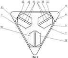
на фиг.2 - фреза, вид сверху;figure 2 - mill, top view;
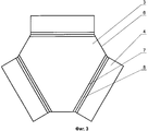
на фиг.3 - развертка фрезы.figure 3 - scan milling cutter.
Фреза для мозаично-шлифовальных машин содержит шлифовальную головку 1 и закрепленные на ней абразивные элементы 2. Шлифовальная головка 1 выполнена из металлического листа, преимущественно стального толщиной 4 мм, и образована основанием 3 и боковинами 4, размещенными под углом к основанию, и днищем 5, имеющим в плане форму треугольника со скругленными вершинами и прикрепленным к нижним кромкам отогнутых боковин 4 параллельно основанию 3. Основание 3 имеет в плане форму треугольника с усеченными вершинами 6. Боковины 4 выполнены заодно целое с основанием 3, причем в месте сгиба сторон 7 треугольника и боковин 4 выполнены канавки 8, относительно которых происходит отгиб боковин 4 относительно основания 3. Между боковинами 4 в зоне усеченных вершин 6 треугольника образованы пазы 9. На наружной поверхности основания 3 жестко закреплены абразивные элементы 2, выполненные в виде трех пар брусков 10 трапециевидной формы, причем трапеции каждой пары обращены друг к другу большими основаниями 11. Бруски 10 закреплены на основании 3 таким образом, что их основания 11 ориентированы от усеченных вершин 6 треугольника к его центру. Бруски 10 каждой пары закреплены либо с зазором 12 относительно друг друга, либо без зазора.The milling cutter for mosaic grinders contains a grinding head 1 and abrasive elements fixed on it 2. The grinding head 1 is made of a metal sheet, mainly
Изготовление и использование устройства осуществляется следующим образом.The manufacture and use of the device is as follows.
Изготовление фрезы осуществляется методом штамповки стального листа. Основание 3 штампуется вместе с боковинами 4. В месте отгиба боковин 4 выполняют канавки 8. Затем нижние кромки боковин 4 прикрепляют к днищу 5, имеющему в плане форму треугольника со скругленными вершинами. К верхней поверхности основания 3 в зоне усеченных вершин 6 треугольника жестко прикрепляют абразивные элементы 2, ориентированные от упомянутых усеченных вершин 6 треугольника к его центру. В предпочтительном варианте исполнения абразивные элементы выполнены в виде брусков 10 трапециевидной формы. Бруски 10 расположены попарно таким образом, что одни концы их больших оснований 11 размещены в зоне усеченных вершин 6 треугольника, а другие концы направлены к центру треугольника. Бруски 10 каждой пары могут располагаться как с зазором 12 относительно друг друга, так и без зазора. Перед началом обработки поверхности фрезу крепят к траверсе, при этом она прилегает к боковинам 4 и фиксируется зажимным кольцом и выступающими частями днища. Включают привод вращения и производят обработку поверхности, например, бетонного пола до полного истирания брусков 10 абразивных элементов, после чего шлифовальную головку снимают и утилизируют. На место изношенной фрезы устанавливают новую и процесс обработки поверхности продолжается. Утилизированные головки отправляют на переплавку.The cutter is manufactured by stamping a steel sheet. The
Выполнение шлифовальных головок полыми из листового металла методом штамповки с жестко прикрепленными к ним абразивными элементами позволяет снизить материалоемкость и трудоемкость изготовления фрез, а следовательно, значительно снизить затраты материалов и электроэнергии на их изготовление. А также уменьшает загрязнение окружающей среды из-за утилизации меньшего количества стали, используемой при изготовлении фрезы.The implementation of grinding heads hollow of sheet metal by stamping with rigidly attached abrasive elements to them reduces the material consumption and laboriousness of the manufacture of mills, and therefore, significantly reduce the cost of materials and electricity for their manufacture. And also reduces environmental pollution due to the disposal of less steel used in the manufacture of mills.
Claims (4)
Priority Applications (1)
| Application Number | Priority Date | Filing Date | Title |
|---|---|---|---|
| RU2006146699/02A RU2337814C2 (en) | 2006-12-27 | 2006-12-27 | Milling tool for processing coating by grinding method |
Applications Claiming Priority (1)
| Application Number | Priority Date | Filing Date | Title |
|---|---|---|---|
| RU2006146699/02A RU2337814C2 (en) | 2006-12-27 | 2006-12-27 | Milling tool for processing coating by grinding method |
Publications (2)
| Publication Number | Publication Date |
|---|---|
| RU2006146699A RU2006146699A (en) | 2008-07-10 |
| RU2337814C2 true RU2337814C2 (en) | 2008-11-10 |
Family
ID=40230507
Family Applications (1)
| Application Number | Title | Priority Date | Filing Date |
|---|---|---|---|
| RU2006146699/02A RU2337814C2 (en) | 2006-12-27 | 2006-12-27 | Milling tool for processing coating by grinding method |
Country Status (1)
| Country | Link |
|---|---|
| RU (1) | RU2337814C2 (en) |
Cited By (1)
| Publication number | Priority date | Publication date | Assignee | Title |
|---|---|---|---|---|
| RU2809347C2 (en) * | 2022-02-18 | 2023-12-11 | Евгений Андреевич Домнин | Abrasive grinding tool |
Citations (1)
| Publication number | Priority date | Publication date | Assignee | Title |
|---|---|---|---|---|
| GB2132551A (en) * | 1982-11-22 | 1984-07-11 | Marcello Toncelli | Rotary diamond-bearing tool |
-
2006
- 2006-12-27 RU RU2006146699/02A patent/RU2337814C2/en not_active IP Right Cessation
Patent Citations (1)
| Publication number | Priority date | Publication date | Assignee | Title |
|---|---|---|---|---|
| GB2132551A (en) * | 1982-11-22 | 1984-07-11 | Marcello Toncelli | Rotary diamond-bearing tool |
Cited By (1)
| Publication number | Priority date | Publication date | Assignee | Title |
|---|---|---|---|---|
| RU2809347C2 (en) * | 2022-02-18 | 2023-12-11 | Евгений Андреевич Домнин | Abrasive grinding tool |
Also Published As
| Publication number | Publication date |
|---|---|
| RU2006146699A (en) | 2008-07-10 |
Similar Documents
| Publication | Publication Date | Title |
|---|---|---|
| JP5844455B2 (en) | Multi polishing tool | |
| JP2005349546A (en) | Grinding tool for side surface circular machining | |
| US6371103B1 (en) | System of modular elements for machining marble, stone and the like | |
| KR20110096153A (en) | Devices for grinding both sides of flat workpieces | |
| US7134949B2 (en) | Constant angular grinding tool | |
| CN220994142U (en) | Grinding wheel with groove easy to drain, slag and chip | |
| KR200474400Y1 (en) | Rotary cutter for rounding and chamferign | |
| TWI577502B (en) | The method of dressing the elastic stone | |
| KR20100093020A (en) | Rotary cutter for rounding and chamfering | |
| KR101845569B1 (en) | Segmented cutting disc | |
| US7833088B1 (en) | Construction method and tool supporting said method | |
| CN214980046U (en) | Diamond grinding tool for grinding machine and grinding machine | |
| JP2023511961A (en) | Methods and articles for manufacturing cutting machines for PDC cutting systems | |
| CN107022959A (en) | A kind of concrete-bridge expansion joint facade grinding head | |
| JP2001009733A (en) | Diamond tools | |
| KR19990039938U (en) | Multi-Axis Grinding Heads for Stone Polishers | |
| KR200444137Y1 (en) | Polishing Wheel Using Diamond Sheet | |
| CN115279986B (en) | Method of manufacturing cutter for PDC cutting system and article | |
| CN210209987U (en) | Sanding device of high-efficiency sanding machine for cooking utensils | |
| CN102837255B (en) | A kind of bistrique of novel stone polishing machine | |
| KR20120133222A (en) | nonwoven grinder | |
| JP2005028513A (en) | Spherical finishing method for processing sphere and spherical finishing processing device for processing sphere | |
| IT202300003585U1 (en) | DIAMOND WHEEL FOR DRY PROCESSING OF CERAMIC PRODUCTS | |
| JP2003326465A (en) | Grooving grinding wheel and composite grinding wheel with the same | |
| JP5693062B2 (en) | Grinding wheel |
Legal Events
| Date | Code | Title | Description |
|---|---|---|---|
| MM4A | The patent is invalid due to non-payment of fees |
Effective date: 20081228 |