Изобретение относится к устройствам электроснабжения безрельсовых транспортных средств и может найти применение на городском электротранспорте - троллейбусах.The invention relates to devices for power supply of rail vehicles and may find application in urban electric vehicles - trolley buses.
Известен штанговый токоприемник, установленный на троллейбусах, например, РТ 6И, содержащий две штанги с горизонтальными шарнирами, помещенными на поворотных по вертикальной оси основаниях. Токосъем с проводов контактной сети осуществляется контактными головками, шарнирно закрепленными на верхних концах штанг, причем провода проходят между щек головок, благодаря чему производится пространственная ориентация штанг токоприемника относительно проводов сети и троллейбуса при его движении, а необходимое усилие нажатия токосъемных головок на провода контактной сети обеспечивают пружины, установленные на нижних концах штанг.Known rod current collector mounted on trolley buses, for example, RT 6I, containing two rods with horizontal hinges placed on the bases rotatable along the vertical axis. The current collector from the wires of the contact network is carried out by contact heads pivotally mounted on the upper ends of the rods, and the wires pass between the cheeks of the heads, due to which the current collector rods are spatially oriented relative to the network wires and the trolleybus during its movement, and the necessary force to press the collector heads on the wires of the contact network provides springs mounted on the lower ends of the rods.
Известна также контактная сеть, с которой производится токосъем описанным выше токоприемником. В контактную сеть входят разнополярные провода, расположенные на расстоянии около 500 мм друг от друга, а также спецчасти, которые осуществляют переход токосъемных головок на разные трассы контактных линий, а также проход головок по криволинейным участкам сети и на пересечениях контактных линий. Однако известная конструкция токоприемника и существующая контактная сеть не обеспечивают надежного токосъема из-за частого схода контактных головок с проводов сети, приводящего к обесточиванию машины и повреждению контактной линии. В любом случае сход головок требует ручных операций со штангами токоприемника. Наличие спецчастей усложняет и загромождает контактную сеть, требует дополнительных затрат на их обслуживание, а также ограничивает скорость движения троллейбуса при проходе спецчастей. Кроме того, необходимость постоянного контакта токопремника с проводами сети не дает возможности троллейбусу, в случае необходимости, расширить границы маневрирования.A contact network is also known with which the current collector is produced by the current collector described above. The contact network includes bipolar wires located at a distance of about 500 mm from each other, as well as special parts that transfer the collector heads to different paths of the contact lines, as well as the heads pass through the curved sections of the network and at the intersections of the contact lines. However, the known design of the current collector and the existing contact network do not provide reliable current collection due to the frequent descent of the contact heads from the wires of the network, leading to a blackout of the machine and damage to the contact line. In any case, the gathering of the heads requires manual operations with the rods of the current collector. The presence of special parts complicates and clutters the contact network, requires additional costs for their maintenance, and also limits the speed of the trolleybus when passing special parts. In addition, the need for constant contact of the current collector with the network wires does not allow the trolley, if necessary, to expand the boundaries of maneuvering.
В качестве прототипа изобретения использована конструкция токоприемника по а.с. №502780 /класс B60L, Капчерин/. Токоприемник выполнен в виде полозообразного каркаса из изолирующего материала с установленными на нем по всей длине токосъемными элементами, каждый из которых имеет длину контактной поверхности меньше, чем расстояние между разнополярными проводами. As a prototype of the invention, the design of the current collector according to A.S. No. 502780 / class B60L, Kapcherin /. The current collector is made in the form of a skid-like frame made of insulating material with current-collecting elements installed on it along the entire length, each of which has a contact surface length less than the distance between the bipolar wires.
Токосъемные элементы расположены в шахматном порядке с перекрытием друг друга, причем каждый из них соединен с электрической нагрузкой через полупроводниковые вентили. Главное достоинство этой конструкции - надежность токосъема. Однако она ограничивает диапазон маневрирования троллейбуса пределом длины токосъемной части, равной габаритной ширине машины. Кроме того, в конструкции задействовано значительное количество полупроводниковых вентилей большой мощности, работающих не постоянно, а периодически.The collector elements are staggered with overlapping each other, and each of them is connected to an electrical load through semiconductor valves. The main advantage of this design is the reliability of current collection. However, it limits the trolleybus maneuvering range to the length of the current-collecting part equal to the overall width of the machine. In addition, a significant number of high-power semiconductor valves are used in the design, which do not work continuously, but periodically.
Задача изобретения - получить надежный токосъем с использованием минимального количества полупроводниковых вентилей, осуществить кратковременную периодическую независимость троллейбуса от проводов контактной сети для расширения диапазона маневрирования и упростить контактную сеть.The objective of the invention is to obtain reliable current collection using a minimum number of semiconductor valves, to realize short-term periodic independence of the trolley bus from the wires of the contact network to expand the range of maneuvering and simplify the contact network.
Указанная задача решается тем, что на электрически изолированном каркасе по всей габаритной ширине троллейбуса устанавливаются только три токосъемных элемента, причем два из них помещены на концах каркаса и электрически изолированы друг от друга, а третий токосъемный элемент помещен в средней части каркаса со смещением по продольной оси машины относительно крайних элементов и электрически связан с каждым из них через полупроводниковой вентиль. Подъем-спуск, а также необходимое нажатие токосъемных элементов на провода сети осуществляют штанги, снабженные пневмоприводом с дистанционным управлением, в контактной сети устраняются спецчасти, а расстояние между разнополярными проводами сети устанавливают в соответствии с длиной контактных элементов.This problem is solved in that only three current collector elements are installed on the electrically insulated frame along the entire overall width of the trolley bus, two of which are placed at the ends of the frame and are electrically isolated from each other, and the third current collector element is placed in the middle of the frame with an offset along the longitudinal axis machines relative to the extreme elements and is electrically connected to each of them through a semiconductor valve. Ascent-descent, as well as the necessary pressing of the collector elements on the network wires, are carried out by rods equipped with a pneumatic actuator with remote control, special parts are eliminated in the contact network, and the distance between the opposite-polarity wires of the network is set in accordance with the length of the contact elements.
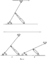
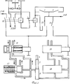
На фиг.1 изображен токоприемник и его отдельные узлы, на фиг.2 - позиции токоприемника, соответствующие режимам работы троллейбуса, а на фиг.3 приведена принципиальная схема управления токоприемником. Токоприемник /ТП/ состоит из диэлектрических планок 2 каркаса с установленными на них тремя токосъемными элементами 1, причем два из них помещены на концах планок и электрически изолированы друг от друга, а третий помещен в средней части планок и смещен по продольной оси троллейбуса относительно первых двух элементов, с каждым из которых он электрически соединен через полупроводниковый вентиль 9 /фиг.3/ Все токосъемные элементы с помощью кабеля подключены к входным клеммам линейного контактора 11. В крайних точках каркаса по габаритной ширине машины установлены конечные включатели 3 с электрически изолированными нажимными элементами. Каркас шарнирно соединен со штангами 7, которые также шарнирно установлены на основании, закрепленному на крыше троллейбуса через изоляторы. Между штангами помещен двухштоковый телескопический пневмоцилиндр 6, верхний шток 4 которого с помощью шарнира прикреплен к поперечине 8 штанг. Величина хода верхнего штока составляет 25-30% от величины хода нижнего штока 5. К рабочим полостям пневмоцилиндра подводится сжатый воздух из общей пневмосистемы троллейбуса. В воздушную магистраль каждой пневмополости включены регуляторы давления воздуха 17 и 18, состоящие из золотника, нагруженного пружиной с регулируемым затягом. Система управления /фиг.3/ содержит пульт управления с переключателями 13 и 14, реле 12 выключения линейного контактора 11 с дополнительными контактами 10, конечные включатели 3 и клапана 15 и 16 управления подачей воздуха в пневмополости. Система управления получает электропитание от источников тока напряжением 24 В /аккумулятора и генератора/. Клапана управления подачей воздуха установлены в магистрали подвода сжатого воздуха перед регуляторами давления 17 и 18, электромагниты привода клапанов подключены к источникам электропитания через трехпозиционный переключатель 13 и выключатель 14. Главные контакты линейного контактора механически связаны с дополнительными контактами 10, которые помещены в цепь питания электромагнита привода клапана управления подачей воздуха в верхнюю пневмополость. Электромагнит включения линейного контактора получает питание от контактной сети через контакты реле 12, обмотка которого подключена к цепи электропитания низкого напряжения через контакты трехпозиционного переключателя, а также и конечные включатели. Исходя из габаритной ширины троллейбуса, длина токосъемного элемента равна 800-850 мм, соответственно расстояние между разнополярными проводами контактной сети устанавливают в 950-1000 мм. Переходные участки контактных линий других направлений движения /маршрутов/ не имеют в своем составе стрелочных узлов, провода сети таких участков монтируют в непосредственной близости от линии первоначального направления с выходом на линию другого направления без использования кривых держателей. Места пересечений контактных линий также не имеют спецчастей, их выполняют с простыми разрывами контактных проводов одной из линий. Из эксплутационной практики известно, что прямолинейное движение троллейбусов на городских улицах с однорядным /в одном направлении/ и двухрядным движением производится в основном в пределах правого крайнего ряда, а на улицах с числом рядов более двух - во втором правом ряду. Учитывая эти особенности, линии контактной сети для одно- и двухрядных улиц монтируют в левой части правого ряда движения, а для многорядных улиц - в правой части второго правого ряда. В местах остановок провода контактных линий на улицах с многорядным движением переводят в первый ряд, обеспечивая возможность контакта ТП троллейбуса с проводами сети при его отходе от остановки после высадки-посадки пассажиров.Figure 1 shows the current collector and its individual nodes, figure 2 - the position of the current collector corresponding to the modes of operation of the trolley, and figure 3 shows a schematic diagram of the control of the current collector. The current collector / TP / consists of dielectric strips 2 of the frame with three current collection elements 1 installed on them, two of which are placed at the ends of the strips and are electrically isolated from each other, and the third is placed in the middle of the strips and offset along the longitudinal axis of the trolley bus elements, with each of which it is electrically connected through a semiconductor valve 9 / Fig. 3/ All current collector elements are connected via cable to the input terminals of the linear contactor 11. At the extreme points of the frame along the overall width e machines are installed end switches 3 with an electrically insulated pressure elements. The frame is pivotally connected to the rods 7, which are also pivotally mounted on a base fixed to the roof of the trolley via insulators. Between the rods is placed a two-rod telescopic pneumatic cylinder 6, the upper rod 4 of which is hinged to the cross member 8 of the rods. The magnitude of the stroke of the upper rod is 25-30% of the stroke of the lower rod 5. Compressed air is supplied to the working cavities of the pneumatic cylinder from the general pneumatic system of the trolleybus. The air line of each pneumatic cavity includes air pressure regulators 17 and 18, consisting of a spool loaded with a spring with an adjustable pull. The control system / 3 / contains a control panel with switches 13 and 14, a relay 12 for switching off a linear contactor 11 with additional contacts 10, end switches 3 and valves 15 and 16 for controlling the air supply to the pneumatic cavity. The control system receives power from 24 V current sources / battery and generator /. The air supply control valves are installed in the compressed air supply line in front of the pressure regulators 17 and 18, the valve drive electromagnets are connected to the power sources through a three-position switch 13 and switch 14. The main contacts of the linear contactor are mechanically connected to additional contacts 10, which are placed in the power supply circuit of the drive electromagnet valves for controlling the air supply to the upper pneumatic cavity. The electromagnet switching on the linear contactor receives power from the contact network through the contacts of the relay 12, the winding of which is connected to the low voltage power supply circuit through the contacts of the three-position switch, as well as the end switches. Based on the overall width of the trolleybus, the length of the collector element is 800-850 mm, respectively, the distance between the bipolar wires of the contact network is set to 950-1000 mm. Transitional sections of contact lines of other directions of movement / routes / do not include arrow nodes, the network wires of such sections are mounted in the immediate vicinity of the line of the original direction with access to the line of another direction without the use of curved holders. The intersections of the contact lines also do not have special parts, they are performed with simple breaks in the contact wires of one of the lines. From operational practice, it is known that the rectilinear movement of trolleybuses on city streets with single-row / in one direction / and two-row traffic is carried out mainly within the right extreme row, and in streets with more than two rows in the second right row. Given these features, the contact network lines for single and double-row streets are mounted on the left side of the right lane, and for multi-row streets - on the right side of the second right lane. In the places of stops, the wires of the contact lines on the streets with multi-lane traffic are transferred to the first row, making it possible for the trolleybus TP to contact the network wires when it moves away from the stop after passengers disembarking and boarding.
Работа управляемого ТП троллейбуса происходит следующим образом. Во время длительной стоянки троллейбуса ТП полностью опущен /фиг.2в/. В этой позиции контакты переключателей 13 и 14 пульта управления в разомкнутом положении. Вследствие этого контакты реле 12 замкнуты, главные и дополнительные контакты линейного контактора 11 из-за отсутствия электропитания на элетромагнитном приводе разомкнуты, золотники клапанов управления подачей воздуха в полости пневмоцилиндра усилием пружин смещены и сообщают полости пневмоцилиндра с атмосферой. Для подъема ТП и установления контакта токосъемных элементов с проводами сети выключателем 14 замыкают цепь питания электропривода клапана 16 управления подачей воздуха в нижнюю пневмополость. Золотник клапана перемещается, перекрывая каналы сообщения полости с атмосферой и открывая доступ воздуха в нее из пневмосистемы. Золотник регулятора 18, ввиду отсутствия заданного затягом пружины давления воздуха в пневмополости, усилием пружины смещен и через каналы сообщает пневмополость с напорной магистралью сжатого воздуха. Под давлением сжатого воздуха шток 5 пневмоцилиндра перемещается, поднимая ТП на величину хода штока /позиция "а" фиг.2/ Затем, при соответствующем положении контактов трехпозиционного переключателя, замыкается цепь питания электропривода клапана 15 управления подачей воздуха в верхнюю пневмополость. Золотник клапана таким же, как и в клапане 16, образом открывает доступ воздуха из напорной магистрали к регулятору давления 17, в котором в результате смещения золотника каналы сообщают напорный трубопровод сжатого воздуха с верхней пневмополостью, в результате чего шток 4 перемещается до контакта токосъемных элементов с проводами сети. Необходимое усилие нажатия на провода обеспечивает регулятор давления, в котором при достижении в пневмополости заданного затягом пружины давления золотник под давлением воздуха перемещается и перекрывает доступ воздуха из напорной магистрали в пневмополость. После установления контакта токосъемника с проводами сети через замкнутые контакты реле 12 получает питание электромагнит включения линейного контактора, его главные контакты, а также дополнительные контакты 10 замыкаются, вследствие чего подается ток высокого напряжения к соответствующим потребителям, а ток низкого напряжения к электроприводу клапана 15, после этого трехпозиционный переключатель устанавливают в нейтральное положение и ТП принимает рабочее положение. При движении троллейбуса по маршруту изменяется высота подвеса проводов контактной сети, из-за чего происходит перемещение ТП вниз или вверх. В любом случае это приводит к нарушению равновесия между усилием затяга пружины регулятора 17 и давлением воздуха на лобовую поверхность его золотника. Перемещение золотника регулятора поддерживает необходимое давление в пневмополости путем впуска-выпуска воздуха из нее, что в конечном итоге обеспечивает постоянное усилие нажатия контактных элементов на провода сети. При значительном изменении высоты подвеса проводов сети, например при проходе контактной линии под искусственными сооружениями, величины хода верхнего штока недостаточно для нормального прохода токоприемника. В этом случае, повышается давление в нижней пневмополости, что приводит к нарушению равновесия давлений в регуляторе 18, восстановлению этого равновесия аналогичным в регуляторе 17 образом, перемещению нижнего штока и сохранению постоянного усилия нажатия ТП на провода сети. Диапазон маневрирования троллейбуса без прерывания токосъема на прямолинейных участках контактных линий находится в пределах 1.5 метров. При приближении любого провода контактной сети к крайней точке токосъема по длине каркаса провод, воздействуя на нажимной элемент одного из конечных выключателей 3, замыкает его контакты. В результате этого, получает питание обмотка реле 12, контакты его размыкаются, обесточивая электропривод линейного контактора, главные и дополнительные контакты размыкаются. При этом отключаются потребители высокого напряжения, а также разрывается цепь питания электропривода клапана управления подачей воздуха к верхней полости пневмоцилиндра. Золотник клапана усилием пружины перемещается, перекрывая доступ воздуха из напорной магистрали в пневмополость и одновременно сообщая ее с атмосферой. Под действием собственного веса ТП опускается на величину хода верхнего штока /фиг.2а/. Кроме того, опускание ТП в эту позицию можно произвести с пульта управления при установке трехпозиционного переключателя в соответствующее положение, в котором обмотка реле 12 также получает электропитание, после чего происходит аналогичное вышеописанному взаимодействие электромеханизмов. Полное опускание токоприемника осуществляют размыканием контактов выключателя 14, после чего обесточивается цепь питания электропривода клапана управления подачей воздуха в нижнюю полость пневмоцилиндра. В результате, золотник клапана 16 таким же, как и в клапане 15, образом перекрывает напорный трубопровод сжатого воздуха и сообщает пневмополость с атмосферой. После этого ТП опускается на величину хода нижнего штока пневмоцилиндра. Таким образом, конструкция исключает повреждение контактной сети и токоприемника, а также возникновение электродуги между проводами сети и токосъемными элементами при прерывании-возобновлении контакта проводов с последними. При необходимости, расширение границ маневра троллейбуса осуществляют без контакта с проводами сети при частично опущенном /позиция а, фиг.2/ ТП, используя инерцию движения машины, с последующим подъемом ТП для возобновления контакта с сетью. Подобным образом можно проходить участки пересечений контактных линий, места искусственных сооружений, а также осуществляют переход на контактные линии других направлений движения. Еще большую независимость от контактной сети троллейбусу даст использование в составе силовой установки накопителей энергии, например инерционных маховиков. В этом случае отпадает необходимость наличия проводов сети в местах остановок для высадки-посадки пассажиров и, кроме того, появляется возможность включения в маршрут троллейбуса участков улиц, необорудованных контактными линиями.The operation of the controlled TP of the trolleybus is as follows. During long-term parking of the trolley, the TP is completely lowered / Fig.2v/. In this position, the contacts of the switches 13 and 14 of the control panel in the open position. As a result, the contacts of the relay 12 are closed, the main and additional contacts of the linear contactor 11 are open due to lack of power on the electromagnetic drive, the spools of the air supply control valves in the cavity of the pneumatic cylinder are displaced by the spring force and communicate the cavity of the pneumatic cylinder with the atmosphere. To raise the TP and establish contact of the collector elements with the network wires, the switch 14 closes the power circuit of the electric actuator of the valve 16 to control the air supply to the lower pneumatic cavity. The valve spool moves, blocking the channels of communication of the cavity with the atmosphere and opening air to it from the pneumatic system. The spool of the regulator 18, due to the absence of the air pressure in the pneumatic cavity defined by the spring pull, the spring force is displaced and through the channels communicates the pneumatic cavity with the compressed air pressure line. Under pressure of compressed air, the rod 5 of the pneumatic cylinder moves, raising the TP by the amount of the stroke / position "a" of figure 2 / Then, with the corresponding position of the contacts of the three-position switch, the power circuit of the electric actuator of the valve 15 controlling the air supply to the upper pneumatic cavity is closed. The valve spool, in the same way as in valve 16, opens up air access from the pressure line to the pressure regulator 17, in which, as a result of the valve spool displacement, the channels communicate the compressed air pressure pipe with the upper pneumatic cavity, as a result of which the rod 4 moves until the collector elements come into contact with network wires. The necessary pressure force on the wires is provided by the pressure regulator, in which, when the pressure in the air cavity reaches the pressure set by the spring tightening, the spool moves under air pressure and blocks the air from the pressure line into the air cavity. After establishing a contact between the current collector and the network wires through closed contacts, the relay 12 receives power from the electromagnet switching on the linear contactor, its main contacts, as well as additional contacts 10, are closed, as a result of which a high voltage current is supplied to the corresponding consumers, and a low voltage current is supplied to the valve actuator 15, after this three-position switch is set to neutral and the TP takes on the working position. When the trolleybus moves along the route, the suspension height of the wires of the contact network changes, because of which the TP moves down or up. In any case, this leads to an imbalance between the tension of the spring of the regulator 17 and the air pressure on the frontal surface of its spool. The movement of the spool of the regulator maintains the necessary pressure in the pneumatic cavity by air inlet-outlet from it, which ultimately provides a constant force of pressing the contact elements on the network wires. With a significant change in the height of the suspension of the network wires, for example, when the contact line passes under artificial structures, the stroke of the upper rod is not enough for the normal passage of the current collector. In this case, the pressure in the lower pneumatic cavity rises, which leads to a violation of the pressure equilibrium in the regulator 18, the restoration of this equilibrium in a similar manner in the regulator 17, the movement of the lower rod and maintaining a constant pressure pressing TP on the network wires. The maneuvering range of the trolleybus without interrupting the current collection on the straight sections of the contact lines is within 1.5 meters. When approaching any wire of the contact network to the extreme point of current collection along the length of the frame, the wire, acting on the pressure element of one of the limit switches 3, closes its contacts. As a result of this, the winding of the relay 12 receives power, its contacts open, de-energizing the electric drive of the linear contactor, the main and additional contacts open. At the same time, consumers of high voltage are disconnected, and the power supply circuit of the electric valve of the control valve for supplying air to the upper cavity of the pneumatic cylinder is broken. The valve spool moves by spring force, blocking the access of air from the pressure line to the pneumatic cavity and at the same time communicating it with the atmosphere. Under the influence of its own weight TP drops by the amount of stroke of the upper rod / Fig.2a/. In addition, the TP can be lowered to this position from the control panel when the three-position switch is installed in the corresponding position, in which the relay coil 12 also receives power, after which the interaction of the electromechanisms similar to that described above occurs. Complete lowering of the current collector is carried out by opening the contacts of the switch 14, after which the power supply circuit of the electric actuator of the air supply control valve to the lower cavity of the pneumatic cylinder is de-energized. As a result, the valve spool 16, in the same way as in the valve 15, closes the pressure line of the compressed air and communicates the pneumatic cavity with the atmosphere. After this, the TP drops by the stroke of the lower rod of the pneumatic cylinder. Thus, the design eliminates damage to the contact network and the current collector, as well as the occurrence of an electric arc between the wires of the network and the collector elements during interruption-resumption of contact of the wires with the latter. If necessary, the expansion of the boundaries of the trolleybus maneuver is carried out without contact with the network wires with partially lowered / position a, Fig. 2 / TP, using the inertia of the machine’s movement, followed by raising the TP to resume contact with the network. In this way, it is possible to cross sections of contact line intersections, places of artificial structures, and also transfer to contact lines of other directions of movement. The use of energy storage devices such as inertial flywheels as part of a power plant will give even greater independence from the contact network to the trolleybus. In this case, there is no need for network wires at the places of stops for disembarkation and boarding of passengers and, in addition, it becomes possible to include sections of streets that are not equipped with contact lines in the trolleybus route.