Изобретение относится к технике радиосвязи и может быть использовано для стереофонического и монофонического радиовещания.The invention relates to radio communications technology and can be used for stereo and monophonic broadcasting.
За прототип принята "Цифровая система радиовещания" [1], содержащая на передающей стороне четыре канала обработки звуковых сигналов, каждый из приемника звука и усилителя звуковой частоты, блок кодирования из четырех АЦП сигнала звука, блок формирования группового сигнала, генератор синусоидальных колебаний, делитель частоты и передатчик в составе генератора несущей частоты, амплитудного модулятора и выходного усилителя, на приемной стороне содержащая цифровой приемник, включающий приемник точных частот и двухполярный амплитудный детектор, последовательно соединенные первый формирователь импульсов, счетчик импульсов, дешифратор и первый распределитель импульсов, первый элемент задержки; элемент НЕ и элемент И, второй и третий элементы задержки, второй распределитель импульсов, второй формирователь импульсов, четыре канала, каждый из которых включает первый ключ, триггер, второй ключ и первый регистр, и последовательно соединенные третий и четвертый ключи, второй регистр, цифроаналоговый преобразователь /ЦАП/, фильтр звуковой частоты, усилитель мощности и громкоговоритель. Частота дискретизации кодов звуковых сигналов 160 кГц. Тактовая частота в системе 9,6 МГц. Коды звуковых сигналов 16-разрядные. Частота следования кодов тактовых импульсов 160 кГц, кодов первого стереосигнала 160 и второго стереосигнала тоже 160 кГц, последовательная суммарная частота следования кодов 480 кГц. Групповой сигнал включает последовательно следующие посылку тактовых импульсов, затем два кода первого стереосигнала /или два моносигнала/ и затем два кода второго стереосигнала /или два моносигнала/. На выходе формирователя группового сигнала единицы в кодах представляются положительными и отрицательными полусинусоидами. Радиосигналы принимаются цифровым приемником приемной стороны, усиливаются, детектируются двухполярным амплитудным детектором, полусинусоиды преобразуются в импульсы, коды звуковых сигналов преобразуются четырьмя ЦАП в аналоговые звуковые сигналы, воспроизводимые громкоговорителями. Недостатками прототипа являются: излишняя затрата мощности передатчика, затрачиваемая на усиление и излучение избыточных в информационном смысле несущей частоты и вторую неиспользуемую боковую частоту, наличие в цифровом приемнике фильтров сосредоточенной избирательности /ФСИ/ во входной цепи и соответствующего числа полосовых фильтров ограничивает число принимаемых вещательных радиостанций. Цель изобретения - уменьшение энергоемкости передатчика и расширение диапазона принимаемых радиовещательных радиостанций. Техническими результатами являются снижение энергоемкости передатчика системы, увеличение числа принимаемых радиостанций приемной стороной.The digital broadcasting system [1] was adopted as a prototype. It contains four channels for processing sound signals, each of a sound receiver and an amplifier of sound frequency, a coding unit of four ADCs of a sound signal, a group signal generating unit, a sine wave generator, and a frequency divider and a transmitter comprising a carrier frequency generator, an amplitude modulator and an output amplifier, at the receiving side comprising a digital receiver including an accurate frequency receiver and a bipolar amplitude detector Ktorov serially connected first pulse generator, a pulse counter, decoder, and the first pulse distributor, first delay element; NOT element and AND element, second and third delay elements, second pulse distributor, second pulse shaper, four channels, each of which includes the first key, trigger, second key and first register, and the third and fourth keys connected in series, second register, digital-to-analog converter / DAC /, audio filter, power amplifier and loudspeaker. The sampling frequency of audio codes is 160 kHz. The clock frequency in the system is 9.6 MHz. Sound codes are 16-bit. The repetition rate of the codes of clock pulses is 160 kHz, the codes of the first stereo signal 160 and the second stereo signal are also 160 kHz, the sequential total frequency of the repetition of codes is 480 kHz. The group signal includes sequentially the following sending of clock pulses, then two codes of the first stereo signal / or two mono signals / and then two codes of the second stereo signal / or two mono signals /. At the output of the group signal former, the units in the codes are represented by positive and negative half-sine waves. Radio signals are received by the digital receiver of the receiving side, amplified, detected by a bipolar amplitude detector, half-sine waves are converted into pulses, sound signal codes are converted by four DACs to analog audio signals reproduced by loudspeakers. The disadvantages of the prototype are: excessive transmitter power spent on amplifying and radiating carrier frequencies that are redundant in the information sense and a second unused side frequency, the presence of concentrated selectivity filters in the digital receiver / input circuit and the corresponding number of bandpass filters limits the number of broadcast radio stations received. The purpose of the invention is to reduce the energy intensity of the transmitter and expand the range of received broadcasting radio stations. The technical results are a decrease in the power consumption of the transmitter of the system, an increase in the number of received radio stations by the receiving side.
Сущность изобретения в том, что в передатчике амплитудный модулятор выполняется из кольцевого модулятора и полосового фильтра, в цифровой приемник вводятся блок управления, блок приема радиосигнала, блок выделения синхроимпульса, синтезатор частот и два приемных регистра.The essence of the invention is that in the transmitter the amplitude modulator is made of a ring modulator and a band-pass filter, a control unit, a radio signal reception unit, a clock extraction unit, a frequency synthesizer, two frequency registers are introduced into the digital receiver.
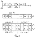
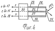
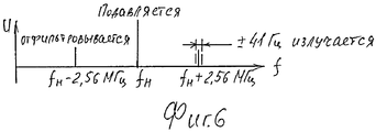
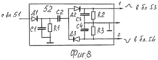
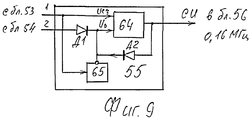
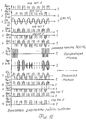
Структурная схема передающей стороны на фиг.1, структура группового потока, излучаемого в эфир, на фиг.2, схема АЦП на фиг.3, конструкция пьезодефлектора на фиг.4, формирователь группового сигнала на фиг.5, спектр амплитудно-модулированного сигнала на фиг.6, цифровой радиоприемник на фиг.7, двухполярный амплитудный детектор на фиг.8, блок выделения синхроимпульса на фиг.9, временные диаграммы работы системы на фиг.10.The structural diagram of the transmitting side in figure 1, the structure of the group stream emitted into the air, in figure 2, the ADC circuit in figure 3, the design of the piezoelectric deflector in figure 4, the group signal shaper in figure 5, the spectrum of the amplitude-modulated signal on Fig.6, the digital radio receiver of Fig.7, the bipolar amplitude detector of Fig.8, the allocation block of the clock in Fig.9, timing diagrams of the system in Fig.10.
Передающая сторона включает /фиг.1/ четыре канала обработки звуковых сигналов, каждый включает последовательно соединенные приемник 1 звука, усилитель 2 звуковой частоты и АЦП 3, четыре АЦП объединены в блок 4 кодирования, формирователь 5 группового сигнала, последовательно соединенные генератор 6 синусоидальных колебаний и делитель 7 частоты, передатчик 8 в составе последовательно соединенных генератора 9 несущей частоты, являющегося умножителем частоты, амплитудного модулятора 10 и выходного усилителя 11. Аналого-цифровые преобразователи /АЦП/ 3 выполнены /фиг.3/ идентично в составе последовательно соединенных управляемого делителя 12 напряжения, блока 13 ключей, согласующего усилителя 14, усилителя 15 и пьезодефлектора 16, источника 17 положительного опорного напряжения, источника 18 отрицательного опорного напряжения, излучатель из импульсного светодиода 19, щелевой диафрагмы 20 и микрообъектива 21, линейки 22 многоэлементного фотоприемника, первого дешифратора 23, шифратора 24 и второго дешифратора 25. Пьезодефлектор 16 является биморфным пьезоэлементом со световым отражателем на торце /фиг.4/, конструктивно выполнен [2, с.119 рис.5.5] из первой 26 и второй 27 пьезопластин, внутреннего электрода 28, первого 29 и второго 30 внешних электродов. Один конец пьезопластин закреплен в держателе 32, на свободном торце расположен световой отражатель 31.The transmitting side includes (Fig. 1/) four channels for processing audio signals, each includes serially connected receiver 1 of sound, amplifier 2 of audio frequency and ADC 3, four ADCs are combined into coding unit 4, generator of group signal 5, series-connected generator 6 of sinusoidal oscillations and frequency divider 7, transmitter 8 as part of a carrier frequency generator 9 connected in series, which is a frequency multiplier, amplitude modulator 10 and output amplifier 11. Analog-to-digital converters / ADC / 3 is executed / Fig. 3/ identically in a series-connected controlled voltage divider 12, block 13 of the keys, matching amplifier 14, amplifier 15 and piezoelectric deflector 16, source 17 of positive reference voltage, source 18 of negative reference voltage, emitter from a pulsed LED 19 , aperture diaphragm 20 and a micro lens 21, a line 22 of a multi-element photodetector, a first decoder 23, an encoder 24 and a second decoder 25. A piezo deflector 16 is a bimorph piezoelectric element with a light reflector rce / Fig. 4/, structurally made [2, p. 119 Fig. 5.5] from the first 26 and second 27 piezoelectric plates, the inner electrode 28, the first 29 and the second 30 outer electrodes. One end of the piezoelectric plates is fixed in the holder 32, at the free end there is a light reflector 31.
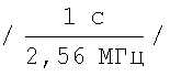
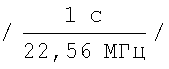
Формирователь 5 группового сигнала /фиг.5/ включает четыре канала, каждый из которых содержит последовательно соединенные приемный регистр 33, блок 34 элементов И из 16-и элементов И и первый элемент ИЛИ 35, включает первый 36 и второй 37 распределители импульсов, последовательно соединенные второй элемент ИЛИ 38, третий элемент ИЛИ 39 и первый выходной ключ 40, последовательно соединенные четвертый элемент ИЛИ 41, элемент 42 задержки и второй выходной ключ 43, включает последовательно соединенные третий ключ 44, формирователь 45 импульсов и счетчик 46 импульсов, выход которого подключен параллельно к сигнальным входам первого 47 и второго 48 ключей. Дискретизация звукового сигнала принимается 160 кГц. Тактовая частота в системе составляет: fт=160 кГц · 16 раз=2,56 МГц, период тактовых импульсов 390 нс . Несущая частота принимается fн=2,56 МГц · 15=38,4 МГц, стабильность несущей 10-6. Верхняя боковая частота fн=38,4+2,56 МГц=40,96 МГц, нижняя боковая частота fниж=38,4 МГц - 2,56 МГц=35,84 МГц. Цифровой приемник включает /фиг.7/ блок 49 управления /выбор радиостанции/, последовательно соединенные блок 50 приема радиосигнала, усилитель 51 радиочастоты и двухполярный амплитудный детектор 52, последовательно соединенные первый формирователь 53 импульсов, блок 55 выделения синхроимпульса /СИ/ и синтезатор 56 частот, включает второй формирователь 54 импульсов, первый 57 и второй 58 приемные регистры, имеющий каждый по 32 разряда, четыре ЦАП 59, четыре включателя 60 и два канала, каждый из которых содержит последовательно соединенные фильтр 61 звуковой частоты, усилитель 62 мощности и громкоговоритель 63. В качестве звукоприемников 1 применяются микрофоны, усилителями 2 являются усилители звуковой частоты, аналоговые сигналы с них поступают на входы своих АЦП 3. Делитель 12 напряжения является семиступенчатым резистивным делителем напряжения, коэффициент передачи которого изменяется сигналами со второго дешифатора 25 при помощи семи ключей блока 13. Сигнал, усиленный усилителем 15, поступает на первый вход пьезодефлектора 16, на второй и третий входы которого поступают опорные напряжения с опорных источников 17 и 18 [2, с.122]. Преобразование сигнала звука в код заключается в развертке луча светодиода 19 отражателем пьезодефлектора 16 по плоскости входных зрачков фотоприемников линейки 22, световой импульс преобразуется в электрический сигнал, возбуждающий соответствующую шину шифратора 24, который и выдает код мгновенного значения входного сигнала. Дискретизация преобразований 160 кГц. Фотоприемниками в линейке 22 являются лавинные фотодиоды ЛФД с временем срабатывания 10 нс. Линейка 22 содержит 1024 фотоприемников для кодирования сигналов 10-разрядным кодом. Разрешающая способность принимается 10 мкВ, что при кодировании 16-разрядным кодом составляет диапазон кодируемого сигнала на входе АЦП от 0 до 0,65536 В. Дешифратор 23 предназначен для коммутации сигнала с фотоприемника линейки 22 и сигнала с дешифратора 25 с соответствующим входом шифратора 24. На выходе шифратора 24 код представляется 16-разрядным. С шифратора 24 код поступает на выход АЦП и на вход второго дешифратора 25, который импульсом с соответствующего выхода открывает соответствующий ключ в блоке 13 для увеличения /или уменьшения/ коэффициента передачи делителя 12 напряжения. При отсутствии сигнала на входе делителя 12 напряжения на вход дешифратора 25 поступает код из нулей. Сигнал с первого выхода блока 25 открывает первый ключ в блоке 13, который подключает к блоку 14 первую ступень делителя 12, определяя коэффициент передачи 1. С ростом амплитуды сигнала звука этот процесс повторяется до появления на выходе шифратора кода 210. С приходом в дешифратор 25 этого кода на втором его выходе появляется сигнал, открывающий второй ключ в блоке 13, коэффициент передачи становится 0,5. С дальнейшим ростом амплитуды в дешифратор 25 поступает код 211, коэффициент передачи делителя 12 равен 0,25, код 212 определяет коэффициент передачи 0,125, код 213 - 0,0625, код 214 - 0,03125, код 215 - 0,015625, который остается до кода 216. При уменьшении амплитуды сигнала идет обратный процесс. Быстродействие преобразования 2×10⁶ преоб/с. Время задержки складывается из срабатываний: фотоприемник ЛФД 10 нс, дешифратор 23-0,2 мкс, шифратор 24-0,2 мкс, дешифратор 25-50 нс [6, с.227, 231, 246], общее время при коде 216 0,5 мкс, что с запасом удовлетворяет дискретизации 160 кГц /6,25 мкс/. Коды с АЦП 3 поступают синхронно и в параллельном виде в свои приемные регистры 33 блока 5, сигналом выдачи кодов является импульс дискретизации с делителя 7 частоты. Коды поступают на первые входы элементов И блоков 34, содержащие по 16 элементов И. Распределители 36 и 37 содержат по 32 выхода /фиг.5/, распределитель 36 обслуживает импульсами элементы И блоков 34 первого и третьего каналов, распределитель 37 импульсов обслуживает импульсами элементы И блоков 34 во втором и четвертом каналах. Входными импульсами для распределителя 36 являются положительные полупериоды синусоид с второго выхода делителя 7 частоты 2,56 МГц, входными импульсами для блока 37 являются отрицательные полусинусоиды 2,56 МГц тоже с второго выхода делителя 7 частоты. Первые 47 и второй 48 ключи открываются сигналом Uот со счетчика 46 импульсов, закрываются ключи сигналом с 32-го выхода блока 36 и 37. Сигнал, закрывающий ключ 43, открывает третий ключ 44, который в открытом состоянии пропускает 16 импульсов частоты 2,56 МГц с четвертого выхода делителя 7 частоты на вход формирователя 45 импульсов, формирующий их по длительности, которые поступают на второй вход третьего элемента ИЛИ 39. Эти же импульсы поступают в пятиразрядный счетчик 46 импульсов. С приходом в него 16 импульсов счетчик формирует код 10000, и со старшего разряда счетчика 46 следует импульс, который открывает ключи 47, 48, закрывает ключ 44 и обнуляет сам счетчик 46. Исходное состояние ключей 47, 48 закрытое, ключа 44 открытое, поэтому с началом работы блока 5 первым кодом с его выхода идет код из 16 единиц - код синхронизации /СИ/, фиг.2. С включением питания ключ 44 пропускает 16 импульсов в формирователь 45 импульсов, с выхода которого импульсы длительностью 195 нс поступают на вход третьего элемента ИЛИ 39 и на вход счетчика 46, сигнал со старшего разряда которого закрывает ключ 44, открывает ключи 47, 48 и обнуляет счетчик 46. В блоки 36, 37 поступают соответственно положительные и отрицательные полусинусоиды 2,56 МГц, с 1-16 выходов блока 36 импульсы поступают на вторые входы элементов И блока 34 первого канала, с 1-16 выходов блока 37 импульсы поступают на вторые входы элементов И блока 34 второго канала. С выходов блока 34 первого канала импульсы кодов через первый 35, второй 38 и третий 39 элементы ИЛИ открывают на время своей длительности 195 нс выходной ключ 40, который в открытом состоянии пропускает одну положительную полусинусоиду /2,56 МГц/ на выход блока 5. С выходов блока 34 второго канала импульсы кодов через первый 35, второй 41 элементы ИЛИ и элемент задержки 42 открывают на время своей длительности 195 нс второй выходной ключ 43, который в открытом состоянии пропускает одну отрицательную полусинусоиду той же частоты /2,56 МГц/ на выход блока 5. Положительные и отрицательные полусинусоиды с ключей 40, 43 представляют символы единиц в кодах первого и второго каналов, поступающие модулирующим сигналом в амплитудный модулятор 10 передатчика. После отработки распределителями 36, 37 первых 16-и импульсов следующие 16 импульсов с выходов 17-32 поступают соответственно на вторые входы элементов И блоков 34 третьего и четвертого каналов. Импульсы с элементов И блока 34 третьего канала через элементы ИЛИ 35, 38, 39 поступают на управляющий вход первого выходного ключа 40, четвертого канала через элементы ИЛИ 35, 41 и элемент 42 задержки поступают на управляющий вход второго выходного ключа 43, с выхода блока 5 следуют коды третьего и четвертого каналов. Импульс с 32-го выхода блока 36 закрывает ключ 47, импульс с 32-го выхода блока 37 закрывает ключ 48 и открывает ключ 44, следует опять выдача кода синхроимпульса, далее процессы повторяются. Один цикл группового сигнала состоит из /фиг.2/ кода СИ, следующего за ним кодов первого, второго каналов и кодов третьего и четвертого каналов: первый, второй, третий и четвертый коды представляют четыре моносигнала или два стереосигнала. Единицы в кодах СИ, первого и третьего каналов представляются положительными полусинусоидами частоты 2,56 МГц, нули их отсутствием, единицы в кодах второго, четвертого каналах представляются отрицательными полусинусоидами той же частоты, нули их отсутствием. Выходной сигнал с блока 5 представляет следование полных или неполных синусоид частотой 2,56 МГц, которые и являются модулирующим сигналом для несущей частоты передатчика. Частота следования кодов СИ 160 кГц, первого и второго сигналов 160 кГц и третьего, четвертого сигналов тоже 160 кГц, суммарная частота следования кодов составляет в эфире 480 кГц. Спектр амплитудно-модулированного сигнала передатчика состоит из несущей и двух боковых частот /верхней и нижней/ фиг.6. Сама несущая частота и одна из боковых частот /не востребованная/ в информационном смысле являются избыточными. Для излучения только одной боковой частоты, несущей и информацию кодов, амплитудный модулятор 10 выполняется из последовательно соединенных кольцевого модулятора и полосового фильтра [3, с.234, 235]. В кольцевом модуляторе подавляется несущая частота, полосовой фильтр отфильтровывает ненужную боковую частоту, в излагаемом варианте нижнюю. Верхняя боковая частота с информацией кодов выдается в выходной усилитель 11 и излучается в эфир, при стабильности несущей частоты 10-6 занимаемая ею полоса в эфире составляет ±41 Гц или 82 Гц. Радиосигнал принимается антенной цифрового приемника /фиг.7/ и поступает на вход блока 50 приема радиосигнала, который является селектором каналов радиовещания с электронной настройкой и включает входную цепь, усилитель радиочастоты и смеситель. Полосовой фильтр усилителя радиочастоты перестраивается напряжением смещения с блока 49 управления: радиочастотный сигнал через петлю связи поступает на эмиттер смесителя, сюда же на смеситель поступает с выхода 3 синтезатора 56 частот частота, равная несущей частоте передатчика, необходимая для детектирования однополосного сигнала [4, с.146]. Сигнал смесителя, являющийся выходным сигналом блока 50, усиливается в усилителе 51 радиочастоты и поступает на вход двухполярного амплитудного детектора 52, выполненного по схеме на фиг.8. Вторые входы блока 56 подключены к вторым выходам блока 49 управления. При включении в блоке 49 требуемого канала радиовещания управляющий сигнал с выхода 2 блока 49 поступает в синтезатора 56 частот и определяет частоту сигнала с третьего выхода блока 56 на третий вход блока 50. Диод Д1 /фиг.8/ выделяет положительную огибающую модулирующего сигнала /фиг.10 диагр.9/. Диод Д2 из модулирующей выделяет огибающие положительных полусинусоид - символы единиц в кодах СИ, первого и третьего сигналов /диагр.10/. Диод Д3 из модулирующей выделяет огибающие отрицательных полусинусоид - символы единиц в кодах второго и четвертого сигналов /диагр.11/. С первого выхода блока 52 продетектированные положительные полусинусоиды /2,56 МГц/ поступают на вход первого формирователя 53 импульсов, со второго выхода блока 52 продетектированные отрицательные полусинусоиды поступают на вход второго формирователя 54 импульсов. Формирователи 53, 54 импульсов выполнены по схеме несимметричного триггера с эмиттерной связью [5, с.209], формирующего прямоугольные импульсы из гармонически изменяющихся сигналов. Импульсы имеют одну полярность и длительность, равную длительности импульсов в кодах передающей стороны. Единицы в кодах представляются наличием импульса, нули их отсутствием, фиг.10 диагр. 12.13). С блока 53 импульсы кодов поступают на информационный вход приемного регистра 57 и на первый вход блока 55 выделения синхроимпульса /СИ/. Информационным входом блока 55 является счетный вход счетчика 64 импульсов /фиг.9/, управляющим входом блока 55 является управляющий вход /Uo/ счетчика 64 импульсов. Информационный вход блока 55 подключен к выходу формирователя 53 импульсов, управляющий его вход через диод Д1 подключен к выходу формирователя 54 импульсов. Счетчик пятиразрядный и ведет счет последовательно идущих 16-и импульсов. При наличии в коде нуля элемент НЕ 65 выдает сигнал, обнуляющий счетчик 64, который начинает счет заново. При поступлении на счетный вход подряд 16 импульсов в счетчике формируется код 1000, и со старшего разряда следует сигнал СИ на первый вход блока 56. Этот же сигнал через диод Д2 обнуляет счетчик 64 импульсов, который может довести счет до 10000 только когда идет код СИ, т.е. код из одних единиц. При поступлении кодов сигналов 1 или 3 с блока 53 в них всегда будет хотя бы один нуль, по которому элемент НЕ 65 будет обнулять счетчик 64, и он не достигнет счета 16 - всегда еще до числа 16 счетчик будет обнуляться. При поступлении кодов сигналов 2 и 4 с блока 54 каждый импульс этих кодов будет также обнулять счетчик 64. Таким образом, на выходе блока 55 невозможно появление сигнала СИ.The group signal generator 5 / Fig. 5/ includes four channels, each of which contains a receiving register 33 connected in series, a block of 34 AND elements of 16 AND elements and a first OR element 35, includes a first 36 and a second 37 pulse distributors connected in series the second OR element 38, the third OR element 39 and the first output key 40, connected in series with the fourth OR element 41, the delay element 42 and the second output key 43, includes the third key 44, the pulse shaper 45 and the impulse counter 46 in series pulses, the output of which is connected in parallel to the signal inputs of the first 47 and second 48 keys. Audio sampling is received at 160 kHz. The clock frequency in the system is: f t = 160 kHz16 times = 2.56 MHz, the period of clock pulses is 390 ns . The carrier frequency is taken f n = 2.56 MHz · 15 = 38.4 MHz, the stability of the carrier 10 -6 . The upper side frequency f n = 38.4 + 2.56 MHz = 40.96 MHz, the lower side frequency f lower = 38.4 MHz - 2.56 MHz = 35.84 MHz. The digital receiver includes / FIG. 7 / control unit 49 / radio station selection /, the radio signal receiving unit 50 connected in series, the radio frequency amplifier 51 and the bipolar amplitude detector 52, the first pulse shaper 53, the sync pulse extraction unit 55 / and the frequency synthesizer 56 connected in series includes a second pulse shaper 54, first 57 and second 58 receiving registers, each having 32 bits, four DACs 59, four switches 60 and two channels, each of which contains a sound filter 61 connected in series frequency amplifier, power amplifier 62 and loudspeaker 63. Microphones are used as sound receivers 1, amplifiers 2 are audio frequency amplifiers, their analog signals are fed to the inputs of their ADC 3. Voltage divider 12 is a seven-step resistive voltage divider, the transmission coefficient of which changes with the second decoder 25 using seven keys of the unit 13. The signal amplified by the amplifier 15 is fed to the first input of the piezoelectric deflector 16, the second and third inputs of which are supplied with reference voltage from reference sources 17 and 18 [2, p.122]. The conversion of the sound signal into code consists in the scanning of the beam of the LED 19 by the reflector of the piezoelectric deflector 16 along the plane of the entrance pupils of the photodetectors of line 22, the light pulse is converted into an electrical signal that excites the corresponding encoder bus 24, which generates a code for the instantaneous value of the input signal. Discretization of conversions 160 kHz. The photodetectors in line 22 are avalanche photodiodes of the APD with a response time of 10 ns. Line 22 contains 1,024 photodetectors for encoding signals with a 10-bit code. The resolution is taken at 10 μV, which when encoded with a 16-bit code is the range of the encoded signal at the ADC input from 0 to 0.65536 V. The decoder 23 is designed to switch the signal from the photodetector of line 22 and the signal from decoder 25 with the corresponding input of encoder 24. On the output of the encoder 24 code is 16-bit. From the encoder 24, the code is fed to the output of the ADC and to the input of the second decoder 25, which, by a pulse from the corresponding output, opens the corresponding key in block 13 to increase / or decrease / transfer coefficient of the voltage divider 12. In the absence of a signal at the input of the voltage divider 12, a code of zeros enters the input of the decoder 25. The signal from the first output of block 25 opens the first key in block 13, which connects to the block 14 the first stage of the divider 12, determining the transmission coefficient 1. With increasing amplitude of the sound signal, this process is repeated until the code 2 10 appears at the output of the encoder. With the arrival of this code in the decoder 25 at its second output, a signal appears that opens the second key in block 13, the transmission coefficient becomes 0.5. With a further increase in the amplitude, code 2 11 enters the decoder 25, the transfer coefficient of the divider 12 is 0.25, code 2 12 determines the transmission coefficient 0.125, code 2 13 - 0.0625, code 2 14 - 0.03125, code 2 15 - 0 , 015625, which remains until code 2 16 . When the signal amplitude decreases, the reverse process occurs. Conversion speed 2 × 10 6 prev / s. The delay time consists of the responses: LFD photodetector 10 ns, decoder 23-0.2 μs, encoder 24-0.2 μs, decoder 25-50 ns [6, p. 227, 231, 246], total time with code 2 16 0.5 μs, which with a margin satisfies the sampling rate of 160 kHz / 6.25 μs /. Codes with ADC 3 arrive synchronously and in parallel form in their receiving registers 33 of block 5, the signal for issuing codes is a sampling pulse from a frequency divider 7. Codes arrive at the first inputs of the elements And blocks 34, containing 16 elements I. The distributors 36 and 37 each contain 32 outputs / Fig. 5/, the distributor 36 serves pulses of the And elements of the blocks 34 of the first and third channels, the distributor 37 of the pulses serves the pulses of the And elements blocks 34 in the second and fourth channels. The input pulses for the distributor 36 are the positive half-periods of the sine waves from the second output of the divider 7 of the frequency 2.56 MHz, the input pulses for the block 37 are the negative half-sine waves of 2.56 MHz also from the second output of the divider 7 of the frequency. The first 47 and second 48 keys are opened by the signal U from the counter 46 pulses, the keys are closed by the signal from the 32nd output of block 36 and 37. The signal closing the key 43 opens the third key 44, which in the open state passes 16 pulses of frequency 2.56 MHz from the fourth output of the frequency divider 7 to the input of the pulse shaper 45, forming them in duration, which are fed to the second input of the third element OR 39. These same pulses are fed into the five-digit counter 46 pulses. With the arrival of 16 pulses into it, the counter generates a code 10000, and from the highest level of the counter 46 there follows a pulse that opens the keys 47, 48, closes the key 44 and resets the counter 46. The initial state of the keys 47, 48 is closed, the key 44 is open, therefore, with the beginning of block 5, the first code from its output is a code of 16 units - synchronization code / SI /, Fig.2. When the power is turned on, the key 44 passes 16 pulses to the pulse shaper 45, the output of which is 195 ns pulses enter the input of the third element OR 39 and the input of the counter 46, the signal from the highest level of which closes the key 44, opens the keys 47, 48 and resets the counter 46. Positive and negative half-sinusoids of 2.56 MHz, respectively, arrive at blocks 36, 37, with 1 -16 outputs of block 36, the pulses are fed to the second inputs of the elements And block 34 of the first channel, from 1-16 outputs of the block 37 pulses are fed to the second inputs of the elements And block 34 of the second channel. From the outputs of block 34 of the first channel, the pulses of the codes through the first 35, second 38, and third 39 elements OR open for the duration of 195 ns an output switch 40, which in the open state passes one positive half-sine wave / 2.56 MHz / to the output of block 5. C the outputs of block 34 of the second channel, the code pulses through the first 35, second 41 OR elements, and the delay element 42 open a second output switch 43 for the duration of 195 ns, which in the open state passes one negative half-sine wave of the same frequency / 2.56 MHz / to the output block 5. Paul and negatively with half-sine keys 40, 43 are in units of symbols codes of the first and second channels, the incoming baseband signal to amplitude modulator 10 transmitter. After the distributors 36, 37 work out the first 16 pulses, the next 16 pulses from the outputs 17-32 are respectively supplied to the second inputs of the elements AND of the blocks 34 of the third and fourth channels. The pulses from the AND elements of the third channel unit 34 through the OR elements 35, 38, 39 enter the control input of the first output key 40, the fourth channel through the OR elements 35, 41 and the delay element 42 go to the control input of the second output key 43, from the output of block 5 followed by codes of the third and fourth channels. The pulse from the 32nd output of block 36 closes the key 47, the pulse from the 32nd output of the block 37 closes the key 48 and opens the key 44, the synchronization code is issued again, then the processes are repeated. One group signal cycle consists of / FIG. 2/ SI code, followed by codes of the first, second channels and codes of the third and fourth channels: the first, second, third and fourth codes represent four mono signals or two stereo signals. Units in the codes of SI, the first and third channels are represented by positive half-sine waves of a frequency of 2.56 MHz, zeros by their absence, units in the codes of the second, fourth channels are represented by negative half-sines of the same frequency, zeros by their absence. The output signal from block 5 represents the sequence of full or incomplete sinusoids with a frequency of 2.56 MHz, which are the modulating signal for the carrier frequency of the transmitter. The repetition rate of SI codes is 160 kHz, the first and second signals are 160 kHz and the third, fourth signals are also 160 kHz, the total repetition rate of codes is on air 480 kHz. The spectrum of the amplitude-modulated signal of the transmitter consists of a carrier and two side frequencies / upper and lower / Fig.6. The carrier frequency itself and one of the side frequencies / not claimed / in the information sense are redundant. To emit only one side frequency, which carries code information, the amplitude modulator 10 is made of series-connected ring modulator and band-pass filter [3, p.234, 235]. In the ring modulator, the carrier frequency is suppressed, the band-pass filter filters out the unnecessary side frequency, in the described embodiment the lower one. The upper side frequency with the code information is issued to the output amplifier 11 and is broadcasted, with a carrier frequency stability of 10 -6, the band occupied by it on the air is ± 41 Hz or 82 Hz. The radio signal is received by the digital receiver antenna (Fig. 7/) and is fed to the input of the radio signal receiving unit 50, which is a selector of broadcasting channels with electronic tuning and includes an input circuit, a radio frequency amplifier, and a mixer. The band-pass filter of the radio-frequency amplifier is tuned by the bias voltage from the control unit 49: the radio-frequency signal is fed through the communication loop to the emitter of the mixer, and here the frequency equal to the carrier frequency of the transmitter, necessary for detecting a single-band signal, is output from output 3 of the synthesizer 56 frequencies [4, p. 146]. The signal of the mixer, which is the output signal of block 50, is amplified in the amplifier 51 of the radio frequency and is fed to the input of a bipolar amplitude detector 52, made according to the circuit in Fig. 8. The second inputs of block 56 are connected to the second outputs of block 49 of the control. When the required broadcasting channel is turned on in block 49, the control signal from the output 2 of block 49 is sent to the frequency synthesizer 56 and determines the frequency of the signal from the third output of block 56 to the third input of block 50. Diode D1 / Fig. 8/ selects the positive envelope of the modulating signal / Fig. 10 diag. 9 /. Diode D2 from the modulating one selects the envelopes of positive half-sinusoids - unit symbols in SI codes, first and third signals / Diagram 10/. Diode D3 from the modulating one selects the envelopes of negative half-sinusoids - unit symbols in the codes of the second and fourth signals / Diagram 11/. From the first output of block 52, the detected positive half-sine waves (2.56 MHz) are fed to the input of the first pulse shaper 53, and from the second output of block 52, the detected negative half-sine waves go to the input of the second pulse shaper 54. Shapers 53, 54 pulses are made according to the scheme of an asymmetric trigger with emitter coupling [5, p.209], which forms rectangular pulses from harmonically changing signals. Pulses have one polarity and a duration equal to the pulse duration in the codes of the transmitting side. Units in the codes are represented by the presence of a pulse, zeros by their absence, Fig. 10 diagram. 12.13). From block 53, the pulses of the codes are fed to the information input of the receiving register 57 and to the first input of the block 55 allocation of the clock / SI /. The information input of block 55 is the counting input of the counter 64 pulses / 9 /, the control input of block 55 is the control input / U o / counter 64 pulses. The information input of block 55 is connected to the output of the pulse shaper 53, its control input through a diode D1 is connected to the output of the pulse shaper 54. The counter is five-digit and keeps a count of 16 consecutive pulses. If the code contains zero, the element NOT 65 gives a signal that resets the counter 64, which starts the counting anew. When 16 pulses are transmitted to the counting input in a row, a 1000 code is generated in the counter, and the SI signal is sent to the first input of block 56 from the highest level. The same signal through the D2 diode resets the 64 pulse counter, which can only count up to 10000 when the SI code is received, those. code of one units. Upon receipt of signal codes 1 or 3 from block 53, they will always have at least one zero, according to which the element HE 65 will reset the counter 64, and it will not reach the count 16 - always before the number 16 the counter will be reset. Upon receipt of signal codes 2 and 4 from block 54, each pulse of these codes will also reset counter 64. Thus, at the output of block 55, the appearance of the SI signal is not possible.
При каждом приходе кода СИ из 16 единиц подряд на выходе блока 55 выдается синхроимпульс СИ, поступающий на первый вход синтезатора 56 частот, по сигналам СИ производится подстройка частоты блока 56, собственная стабильность которого 10-5. Синтезатор 56 частот выдает: с первого выхода импульсы тактовой частоты 2,56 МГц для заполнения разрядов приемных регистров 57, 58 импульсами кодов, со второго выхода сигналы Uвыд частотой 160 кГц, с третьего выхода синусоидальные колебания соответствующей несущей частоты на третий вход блока 50. С формирователя 53 импульсов коды первого и третьего каналов заполняют разряды: с первого по 16 импульсами кода первого сигнала и с 17-го по 32-й импульсами кода третьего сигнала. С формирователя 54 импульсов коды второго и четвертого сигналов заполняют разряды: с первого по 16 импульсами кода второго сигнала и с 17-го по 32-й импульсами кода четвертого сигнала. Коды с приемных регистров 57, 58 выдаются в параллельном виде в ЦАП 59 своего канала, которые преобразуют их в аналоговые сигналы звука, которые после прохода фильтра 61 звуковой частоты усиливаются в усилителях 62 мощности и поступают в громкоговорители 63. Смена станций радиовещания производится с блока 49 управления выдачей с него соответствующего напряжения смещения в блок 50 приема радиосигнала.At each arrival of the SI code from 16 units in a row, the SI clock pulse is output at block 55 output to the first input of the frequency synthesizer 56, and the frequency of block 56 is tuned according to the SI signals, and its own stability is 10 -5 . Frequency synthesizer 56 outputs: a first output pulses of the clock frequency of 2.56 MHz for filling bits receiving registers 57, 58 pulses of codes, from the second output signals U vyd frequency of 160 kHz output from the third sinusoidal oscillations corresponding to the carrier frequency to the third input of the block 50. From the 53 pulse shaper, the codes of the first and third channels fill the bits: from the first to 16 pulses of the code of the first signal and from the 17th to 32th pulses of the code of the third signal. From the generator 54 pulses, the codes of the second and fourth signals fill the bits: from the first to 16 pulses of the code of the second signal and from the 17th to 32th pulses of the code of the fourth signal. Codes from the receiving registers 57, 58 are issued in parallel to the DAC 59 of their channel, which convert them into analog audio signals, which, after passing the sound filter 61, are amplified in power amplifiers 62 and fed into loudspeakers 63. The broadcasting stations are changed from block 49 control the issuance of the corresponding bias voltage to the block 50 receiving the radio signal.
Работа системы.System operation.
Звуковые колебания принимаются приемниками 1 звука, усиливаются и преобразуются АЦП 3 в 16-разрядные коды. С АЦП 3 коды поступают в приемные регистры 33 /фиг.5/ формирователя 5 группового сигнала, формирующего групповой сигнал в составе трех посылок: 16-разрядного кода СИ, 16-разрядных кодов первого и второго сигналов и 16-разрядных кодов сигналов третьего и четвертого /Фиг.2/.Sound vibrations are received by the sound receivers 1, amplified and converted by the ADC 3 into 16-bit codes. With the ADC 3, the codes are received in the receiving registers 33 / Fig. 5/ of the group signal shaper 5, which forms the group signal in three packages: 16-bit SI code, 16-bit codes of the first and second signals and 16-bit codes of signals of the third and fourth / Fig. 2/.
Блок 5 преобразует параллельные коды в последовательные и заменяет в них символы единиц с импульсов на положительные и отрицательные полусинусоиды. Несущая частота 38,4 МГц модулируется синусоидальными колебаниями, в амплитудном модуляторе 10 подавляется несущая и отфильтровывается нижняя боковая частота, верхняя боковая частота 40,96 МГц усиливается и излучается в эфир, занимая полосу 82 Гц. В цифровом приемнике блоком 49 управления настраивается блок 50 приема радиосигнала на нужный радиоканал и принимает одновременно четыре монофонических программы или две стереофонических /или одну квадрофоническую программу/. Радиосигналы детектируются блоком 52, формирователи 53, 54 возвращают представление единиц в кодах с полусинусоид в импульсы. Код СИ выделяется блоком 55, импульсы с которого подстраивают частоту синтезатора частот 56 к частоте передающей стороны. Коды сигналов 1 и 3 поступают в приемный регистр 57, коды сигналов 2 и 4 поступают в приемный регистр 58, с которых они синхронно выдаются в ЦАП 59. Для прослушивания стереофонической передачи пользователь включателем 60 подключает первый и второй сигналы или 3 и 4 сигналы к входам соответственно блоков 61. Для прослушивания монофонической программы пользователь подключает соответствующим включателем 60 соответствующий ЦАП 59 к блоку 61 фильтров звуковой частоты. Усиленные звуковые сигналы воспроизводятся громкоговорителями 63. Предложенная система радиовещания решает проблему распределения частотного ресурса, так как полоса, занимаемая всего 82 Гц, уменьшает энергоемкость передатчика: при полосе 82 Гц нужна много меньше мощность передатчика, чем при излучении несущей и двух боковых частот, повышает помехоустойчивость: спектр частот помех широк, а на долю 82 Гц придется мизерная часть энергии помехи, к тому же синусоидальный сигнал наименее подвергается искажениям, способствует электромагнитной совместимости: узкая полоса способствует лучше разнести частоты, передача четырех вещательных программ по одному радиоканалу параллельно позволяет снизить энергоемкость передатчиков государственной сети радиовещания в четыре раза /можно снизить и в восемь раз/.Block 5 converts parallel codes into sequential ones and replaces unit symbols from pulses with positive and negative half-sine waves in them. The carrier frequency of 38.4 MHz is modulated by sinusoidal oscillations, in the amplitude modulator 10 the carrier is suppressed and the lower side frequency is filtered out, the upper side frequency of 40.96 MHz is amplified and radiated, occupying the 82 Hz band. In the digital receiver, the control unit 49 adjusts the radio signal receiving unit 50 to the desired radio channel and simultaneously receives four monophonic programs or two stereo / or one quadraphonic program /. Radio signals are detected by block 52, shapers 53, 54 return the representation of units in half-sine codes to pulses. The SI code is allocated by block 55, the pulses from which adjust the frequency of the frequency synthesizer 56 to the frequency of the transmitting side. Signal codes 1 and 3 are received in the receive register 57, signal codes 2 and 4 are received in the receive register 58, from which they are synchronously output to the DAC 59. To listen to a stereo transmission, the user switches on the first and second signals 60 or 3 and 4 signals to the inputs blocks 61, respectively. To listen to the monophonic program, the user connects the corresponding DAC 59 to the block 61 of the audio frequency filters with the corresponding switch 60. Amplified sound signals are reproduced by loudspeakers 63. The proposed broadcasting system solves the problem of frequency resource distribution, since the band occupied by only 82 Hz reduces the energy consumption of the transmitter: when the band is 82 Hz, the transmitter power is much less than that of the carrier and two side frequencies, and it increases the noise immunity : the spectrum of interference frequencies is wide, and the fraction of the interference energy will fall to a fraction of 82 Hz; moreover, the sinusoidal signal is less affected by distortion, and compatibility: a narrow band contributes to a better spread of frequencies, the transmission of four broadcast programs on one radio channel in parallel allows to reduce the energy consumption of transmitters of the state broadcasting network by four times / can be reduced by eight times /.
Использованные источникиUsed sources
1. Патент №2048704 C1, кл. Н04Н 5/00, бюл. №32 от 20.11.95, прототип.1. Patent No. 2048704 C1, cl. H04H 5/00, bull. No. 32 dated 11/20/95, prototype.
2. И.В.Фридлянд, В.Г.Сошников. Системы автоматического регулирования в устройствах видеозаписи. М., 1988, с.119 рис.5.5, с.122 рис.5.10.2. I.V. Fridlyand, V.G. Soshnikov. Automatic control systems in video recording devices. M., 1988, p.119 fig.5.5, p.122 fig.5.10.
3. Радиопередающие устройства. М.С.Шумилин и др. М., 1981, с.234-235.3. Radio transmitting devices. M.S. Shumilin et al. M., 1981, p. 234-235.
4. Радиосвязь, вещание и телевидение, под ред. А.Д.Фортушенко. М., 1981, с.146.4. Radio communications, broadcasting and television, ed. A.D. Fortushenko. M., 1981, p. 146.
5. В.Ф.Баркан, В.К.Жданов. Усилительная и импульсная техника. М., 1981, с.209.5. V.F. Barkan, V.K. Zhdanov. Amplification and impulse technology. M., 1981, p. 209.
6. Цифровые интегральные микросхемы. Справочник. Минск, 1991, с.227, 231, 246.6. Digital integrated circuits. Directory. Minsk, 1991, p. 227, 231, 246.