RU2391237C1 - Osipov test bench for vehicle brakes diagnostics - Google Patents
Osipov test bench for vehicle brakes diagnostics Download PDFInfo
- Publication number
- RU2391237C1 RU2391237C1 RU2008139838/11A RU2008139838A RU2391237C1 RU 2391237 C1 RU2391237 C1 RU 2391237C1 RU 2008139838/11 A RU2008139838/11 A RU 2008139838/11A RU 2008139838 A RU2008139838 A RU 2008139838A RU 2391237 C1 RU2391237 C1 RU 2391237C1
- Authority
- RU
- Russia
- Prior art keywords
- wheels
- brakes
- movable
- diagnostics
- braking
- Prior art date
Links
Images

Landscapes
- Force Measurement Appropriate To Specific Purposes (AREA)
- Regulating Braking Force (AREA)
Abstract
Description
Изобретение относится к области машиностроения, а именно к диагностированию тормозов автотранспортных средств (АТС).The invention relates to the field of engineering, namely to diagnose brakes of motor vehicles (ATS).
Известен платформенный инерционный тормозной стенд (Техническая эксплуатация автомобилей: Учебник для вузов / Под ред. Г.В.Крамаренко. - 2-е изд., перераб. и доп. - М.: Транспорт, 1983. С.148, рис.6.35 [1]) с подвижными платформенными опорами для установки колес диагностируемого АТС.Known platform inertial brake stand (Technical operation of cars: Textbook for universities / Edited by G.V. Kramarenko. - 2nd ed., Revised and added. - M.: Transport, 1983. P.148, Fig. 6.35 [1]) with movable platform supports for installing the wheels of the diagnosed ATS.
К недостаткам этого стенда относится большая площадь, необходимая для разгона АТС, зависимость результатов от точности заезда на платформы, нестабильность коэффициента сцепления, необходимость повторных контрольных заездов.The disadvantages of this stand include the large area needed to disperse the PBX, the dependence of the results on the accuracy of the race on the platforms, the instability of the adhesion coefficient, the need for repeated control races.
Известен тормозной стенд с подвижными секциями, на которых располагаются роликовые опоры для колес испытываемой оси с приводом от электродвигателя (Патент 2316438, RU, МПК7 В60Т 17/22, G01L 5/28. Устройство для диагностирования тормозной системы автотранспортного средства. Заявка 2006115873 от 10.05.2006. Зарегистрировано 10.02.2008 [2]).Known brake stand with movable sections on which are located roller bearings for the wheels of the axle under test driven by an electric motor (Patent 2316438, RU, IPC 7 В60Т 17/22, G01L 5/28. Device for diagnosing a brake system of a vehicle. Application 2006115873 from 10.05 .2006. Registered on 10.02.2008 [2]).
К недостаткам этого стенда относятся затраты электроэнергии, сложность подвески подвижных секций, нестабильность коэффициента сцепления, несоответствие процесса торможения реальным дорожным условиям из-за изменения площади контакта колес с опорными роликами.The disadvantages of this stand include the cost of electricity, the complexity of the suspension of the movable sections, the instability of the coefficient of adhesion, the mismatch of the braking process with real road conditions due to changes in the contact area of the wheels with the support rollers.
Известен тормозной стенд с роликовыми опорами, привод которых осуществляется гидравлическим силовым цилиндром с ручным насосом (Патент 2193984 С2, RU, МПК7 В60Т 17/22, G01M 17/007. Гидромеханический силоизмерительный стенд для диагностирования тормозов автотранспортных средств. Заявка 2000126918/28 от 2000.10.26. Опубликован 2002.12.10 [3]).A known brake stand with roller bearings, the drive of which is carried out by a hydraulic power cylinder with a hand pump (Patent 2193984 C2, RU, IPC 7 V60T 17/22, G01M 17/007. Hydromechanical force measuring stand for diagnosing vehicle brakes. Application 2000126918/28 from 2000.10 .26. Published 2002.12.10 [3]).
Недостатком этого стенда является ручной привод, зависимость результатов диагностирования от коэффициента сцепления колес испытываемой оси с опорными роликами, погрешности в определении тормозной силы, а также несоответствие процесса торможения реальным дорожным условиям.The disadvantage of this stand is the manual drive, the dependence of the diagnostic results on the coefficient of adhesion of the wheels of the axle under test with the support rollers, errors in determining the braking force, as well as the mismatch of the braking process with real road conditions.
Наиболее близким техническим решением, принятым в качестве прототипа, является стенд для диагностирования тормозов АТС (Патент 2323841 С1, RU, МПК В60Т 17/22, G01L 5/28. Стенд для диагностирования тормозов автотранспортных средств. Заявка 2006124360/11 от 2006.07.06. Опубликован 2008.05.10 [4]).The closest technical solution adopted as a prototype is a stand for diagnosing ATS brakes (Patent 2323841 C1, RU, IPC B60T 17/22, G01L 5/28. A stand for diagnosing vehicle brakes. Application 2006124360/11 of 2006.07.06. Published 2008.05.10 [4]).
Общими признаками прототипа с заявляемым стендом являются: две подвижные опоры с горизонтальной контактной поверхностью для установки колес испытываемой оси, привод подвижных опор от силового цилиндра, шариковые направляющие для перемещения подвижных опор в продольном направлении.Common features of the prototype with the claimed stand are: two movable bearings with a horizontal contact surface for installing the wheels of the tested axis, the drive of the movable bearings from the power cylinder, ball guides for moving the movable bearings in the longitudinal direction.
Недостатками прототипа являются:The disadvantages of the prototype are:
- диагностирование тормозов в статике при заблокированных не вращающихся колесах;- diagnosis of brakes in statics with non-rotating wheels locked;
- невозможность количественной оценки диагностических параметров процесса торможения в динамике из-за отсутствия соответствующих измерительных устройств;- the inability to quantify the diagnostic parameters of the braking process in the dynamics due to the lack of appropriate measuring devices;
- невозможность количественной оценки устойчивости АТС при торможении;- the inability to quantify the stability of the vehicle during braking;
- большая металлоемкость в виду наличия в приводе подвижных опор верхней и нижней рам, их направляющих, шарниров, осей и т.д;- large metal consumption in view of the presence in the drive of the movable bearings of the upper and lower frames, their guides, hinges, axles, etc;
- большая масса подвижных опор (столов) с бетонным покрытием;- a large mass of movable supports (tables) with concrete coating;
- стационарность расположения из-за привязки силового оборудования к яме;- Stationary location due to the binding of power equipment to the pit;
- капитальные затраты при монтаже в связи с необходимостью подготовки для стенда специального фундамента с ямой.- capital costs during installation due to the need to prepare for the stand a special foundation with a pit.
Заявляемое изобретение направлено на решение задачи обеспечения качества определения в динамике диагностических параметров тормозов и установления устойчивости АТС при торможении, а также создания при стендовых испытаниях с наименьшими энергетическими затратами условий, наиболее полно имитирующих реальные условия торможения АТС на дороге.The claimed invention is aimed at solving the problem of ensuring the quality of determining the dynamics of the diagnostic parameters of the brakes and establishing the stability of the ATS during braking, as well as creating conditions during bench tests with the lowest energy costs that most fully simulate the real braking conditions of the ATS on the road.
В соответствии с поставленной задачей техническим результатом изобретения является определение текущих значений параметров эффективности торможения левого и правого колеса испытываемой оси и оценка устойчивости АТС при торможении, а также повышение достоверности результатов диагностирования тормозов АТС в целом за счет приближения условий стендовых испытаний к реальным дорожным условиям.In accordance with the task, the technical result of the invention is to determine the current values of the braking efficiency parameters of the left and right wheels of the axle under test and assess the stability of the ATS during braking, as well as increase the reliability of the results of diagnosing ATS brakes in general by approximating bench test conditions to real road conditions.
Технический результат изобретения достигается тем, что в патентуемом стенде для диагностирования тормозов АТС, содержащем две подвижные в продольном направлении опоры с горизонтальной контактной поверхностью для установки колес испытываемой оси, привод опор, выполненный на основе силового цилиндра, шариковые направляющие для перемещения подвижных опор в продольном направлении, согласно изобретению, подвижные опоры не имеют жесткой связи между собой и приводятся в движение раздельно двумя самостоятельными силовыми цилиндрами от одной общей пневмо или гидросистемы, имеется устройство, сигнализирующее о начале движения подвижных опор, имеется устройство для определения усилия на тормозной педали и ее автоматического привода (педаметр), горизонтальная контактная поверхность подвижных опор имеет полимерное покрытие с коэффициентом сцепления не меньше 0,8, на каждой подвижной опоре установлены датчики веса, начала движения и силы, сигналы от которых через усилитель и аналого-цифровой преобразователь поступают на обработку в компьютер, выдающий на распечатывающее устройство (принтер) и экран монитора результаты диагностирования тормозов каждого колеса.The technical result of the invention is achieved by the fact that in the patented stand for diagnosing brakes of ATS, containing two longitudinally movable bearings with a horizontal contact surface for mounting the wheels of the axle under test, a drive of bearings made on the basis of a power cylinder, ball guides for moving the movable bearings in the longitudinal direction , according to the invention, the movable bearings do not have a rigid connection with each other and are driven separately by two independent power cylinders from one of the common pneumatic or hydraulic system, there is a device that signals the beginning of the movement of the movable bearings, there is a device for determining the force on the brake pedal and its automatic drive (pedameter), the horizontal contact surface of the movable bearings has a polymer coating with an adhesion coefficient of at least 0.8, on Sensors of weight, the beginning of movement and force are installed on each movable support, the signals from which are fed to the computer through an amplifier and an analog-to-digital converter, which issues to the print oystvo (printer) and the monitor screen of diagnosing each wheel brake.
Отличием от прототипа является:The difference from the prototype is:
- отсутствие жесткой связи между подвижными платформами, что позволяет качественно диагностировать каждое левое и правое колесо и давать объективную количественную оценку устойчивости АТС при торможении;- the absence of a rigid connection between mobile platforms, which allows to qualitatively diagnose each left and right wheel and to give an objective quantitative assessment of the stability of the ATS during braking;
- наличие раздельного привода каждой подвижной опоры самостоятельным силовым цилиндром от одной общей пневмо или гидросистемы;- the presence of a separate drive for each movable support with an independent power cylinder from one common pneumatic or hydraulic system;
- наличие устройства, сигнализирующего о начале движения подвижных опор;- the presence of a device that signals the beginning of the movement of movable supports;
- наличие устройства для определения усилия на тормозной педали и ее автоматического привода;- the presence of a device for determining the force on the brake pedal and its automatic drive;
- наличие на горизонтальных контактных поверхностях подвижных опор полимерного покрытия с коэффициентом сцепления не меньше 0,8;- the presence on the horizontal contact surfaces of the movable supports of the polymer coating with a coefficient of adhesion of not less than 0.8;
- наличие на подвижных опорах стенда датчиков веса, начала движения и силы;- the presence on the movable supports of the stand of sensors of weight, the beginning of movement and force;
- наличие компьютерной измерительной системы, содержащей усилитель сигналов всех датчиков и измерительных устройств, аналого-цифровой преобразователь, компьютер с распечатывающим устройством и монитором.- the presence of a computer measuring system containing an amplifier of signals from all sensors and measuring devices, an analog-to-digital converter, a computer with a printing device and a monitor.
Наличие новой совокупности существенных отличительных от прототипа признаков в заявляемом стенде для диагностирования тормозов АТС позволяет сделать вывод о соответствии заявляемого изобретения критерию «новизна».The presence of a new set of essential distinctive features from the prototype in the inventive stand for diagnosing brakes of automatic telephone exchanges allows us to conclude that the claimed invention meets the criterion of "novelty."
Проведенный дополнительный сопоставительный анализ патентной и научно-технической информации не выявил источники, содержащие сведения об известности совокупности отличительных признаков заявляемого стенда для диагностирования тормозов АТС, что свидетельствует о его соответствии критерию «изобретательский уровень».An additional comparative analysis of patent and scientific and technical information did not reveal sources containing information about the prominence of the combination of distinctive features of the inventive stand for diagnosing ATS brakes, which indicates its compliance with the criterion of "inventive step".
Сущность изобретения поясняется чертежом, где на фиг.1 схематично показан заявляемый стенд для диагностирования тормозов АТС.The invention is illustrated in the drawing, where figure 1 schematically shows the inventive stand for diagnosing brakes of the vehicle.
Стенд содержит две не связанные между собой подвижные опоры 1 для установки колес испытываемой оси АТС. Привод каждой опоры осуществляется самостоятельным силовым цилиндром 2 от одной общей пневмо- или гидросистемы 3. Под действием силового цилиндра 2 опора 1 имеет возможность перемещаться в продольном направлении на шариковых направляющих 4 навстречу АТС. Возврат каждой опоры 1 в исходное положение осуществляется за счет пружин сжатия 5. На видном из кабины АТС месте установлено устройство 6, сигнализирующее о начале движения подвижных опор. В комплектацию стенда входит устройство 7 для определения усилия на тормозной педали и ее автоматического привода (педаметр), а также два упора 8, исключающие при диагностировании откат АТС назад. На каждой подвижной опоре 1 установлен датчик веса 9, датчик начала движения 10 и датчик силы 11. Сигналы от всех вышеперечисленных датчиков и измерительных устройств поступают в компьютерную измерительную систему, содержащую усилитель сигналов 12, аналого-цифровой преобразователь 13, компьютер 14, распечатывающее устройство 15 и монитор 16.The stand contains two unrelated movable bearings 1 for mounting the wheels of the tested axis of the ATS. The drive of each support is carried out by an independent power cylinder 2 from one common pneumatic or hydraulic system 3. Under the action of the power cylinder 2, the support 1 has the ability to move in the longitudinal direction on ball guides 4 towards the ATS. The return of each support 1 to its original position is carried out by means of compression springs 5. A device 6 is installed in a place visible from the PBX cab, signaling the beginning of the movement of the movable supports. The stand is equipped with a device 7 for determining the force on the brake pedal and its automatic drive (pedameter), as well as two stops 8, which exclude the automatic vehicle rollback back when diagnosing. A weight sensor 9, a start-up sensor 10, and a force sensor 11 are installed on each movable support 1. The signals from all of the above sensors and measuring devices are fed to a computer measuring system containing a signal amplifier 12, an analog-to-digital converter 13, a computer 14, a printing device 15 and monitor 16.
Диагностирование тормозов АТС на заявленном стенде осуществляется по авторской методике, отличающейся от известных методов диагностирования тем, что в ней при постановке диагноза эффективности тормозов и устойчивости АТС при торможении, наряду с параметрами регламентируемыми ГОСТ Р 51709-2001 (ГОСТ Р 51709-2001. Автотранспортные средства. Требования безопасности к техническому состоянию и методы проверки. - Взамен ГОСТ 25478-91; введ. 2002-01-01 - М.: Госстандарт России: Изд-во стандартов, 2001.-44 с. [5]): усилием на органе управления РП, удельной тормозной силой YТ, относительной разностью тормозных сил F, а также временем срабатывания тормозной системы τСР=(τС+τН) (при дорожных испытаниях), используются новые высокоинформативные оценочные параметры: коэффициент неравномерности нарастания тормозного момента КННМ, характеризующий различие в интенсивности роста тормозного момента на колесах одной оси, коэффициент неравномерности блокирования колес одной оси по времени КНБ и разворачивающий момент МРАЗВ., характеризующий устойчивость АТС при торможении.Diagnosis of ATS brakes at the claimed stand is carried out according to the author’s method, which differs from known diagnostic methods in that when diagnosing the effectiveness of brakes and ATS stability during braking, along with the parameters regulated by GOST R 51709-2001 (GOST R 51709-2001. Safety requirements for the technical condition and verification methods. - Instead of GOST 25478-91; introduced 2002-01-01 - M .: Gosstandart of Russia: Publishing house of standards, 2001.-44 p. [5]): effort on the organ control P P , specific braking force y Y T , the relative difference of the braking forces F, as well as the response time of the braking system τ СР = (τ С + τ Н ) (during road tests), new highly informative estimation parameters are used: the coefficient of non-uniformity of the increase in braking torque K NNM , which characterizes the difference in intensity the growth of the braking torque on the wheels of one axis, the coefficient of unevenness of the blocking of the wheels of one axis in time To NB and the unfolding moment M DEVELOPMENT. , characterizing the stability of the vehicle during braking.
Численная величина коэффициента КННМ определяется из выраженияThe numerical value of the coefficient K NNM is determined from the expression
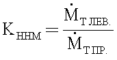
где ![]()
![]()
![]()
![]()
Коэффициент неравномерности блокирования колес оси по времени КНБ определяется какThe unevenness coefficient of blocking the axle wheels in time K NB is defined as
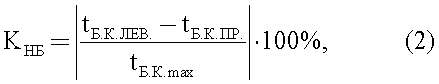
где tБ.K.ЛЕВ., tБ.К.ПР. - время блокирования левого, правого колеса одной оси.where t B.K. , t B.K. - blocking time of the left, right wheel of one axis.
Разворачивающий момент МРАЗВ. определяется по формуле Turning Point M DEVELOPMENT. determined by the formula
![]()
![]()
где RX - значения продольных реакций колес;where R X - the values of the longitudinal reactions of the wheels;
ВА - колея автомобиля.In A - the track of the car.
Согласно авторской методике диагностирование тормозов на заявленном стенде осуществляется в следующей последовательности.According to the author's technique, the diagnosis of brakes at the claimed stand is carried out in the following sequence.
1. АТС въезжает (устанавливается) колесами исследуемой оси на подвижные опоры 1 стенда.1. ATS enters (is installed) by the wheels of the axis under study on the movable supports of 1 stand.
2. АТС фиксируется от перемещения в продольном направлении назад с помощью двух упоров 8, устанавливаемых под колеса не исследуемой оси.2. ATS is fixed from moving in the longitudinal direction back with the help of two stops 8, mounted under the wheels of the axis not studied.
3. На педаль тормоза устанавливается устройство 7 для определения усилия и автоматического привода педали.3. A device 7 is installed on the brake pedal to determine the force and automatically drive the pedal.
5. В пневматической (гидравлической) системе привода 3 устанавливается давление, соответствующее номинальному усилию торможения диагностируемого АТС.5. The pneumatic (hydraulic) drive system 3 sets the pressure corresponding to the rated braking force of the diagnosed ATS.
6. Выхлопная труба АТС, при диагностировании последнего в закрытом помещении, соединяется с системой отсоса отработавших газов, и пускается двигатель для приведения тормозной системы в рабочее состояние.6. The exhaust pipe of the ATS, when diagnosing the latter in an enclosed space, is connected to the exhaust gas exhaust system, and the engine is started to bring the brake system to working condition.
7. Автоматически или диагностом (оператором) вручную включается в работу система привода 3, и в силовые цилиндры 2 поступает рабочее тело - сжатый воздух или жидкость.7. Automatically or by a diagnostician (operator), the drive system 3 is manually put into operation, and the working fluid — compressed air or liquid — enters the power cylinders 2.
8. Под действием давления рабочего тела силовые цилиндры 2 перемещают на шариковых направляющих 4 подвижные опоры 1 в продольном направлении навстречу АТС, приводя его колеса во вращение.8. Under the influence of the pressure of the working fluid, the power cylinders 2 move the movable bearings 1 in the longitudinal direction towards the automatic telephone exchange on the ball guides 4, bringing its wheels into rotation.
9. При движении подвижных опор 1 срабатывают расположенные на них датчики начала движения 10, и включается устройство 6, сигнализирующее о начале движения подвижных опор.9. When moving the movable supports 1, the sensors located on them start to move 10, and the device 6 is turned on, signaling the beginning of the movement of the movable supports.
10. По сигналу устройства 6 автоматически посредством устройства 7 для определения усилия на тормозной педали и ее автоматического привода или непосредственно водителем производится торможение вращающихся колес испытываемой оси;10. At the signal of the device 6, automatically by means of the device 7 for determining the force on the brake pedal and its automatic drive or directly by the driver, the rotating wheels of the axle under test are braked;
11. В процессе торможения колес испытываемой оси сигналы с устройства 7, расположенного на тормозной педали, и датчиков веса 9, датчиков начала движения 10, датчиков силы 11, расположенных на подвижных опорах 1, поступают на усиление в усилитель сигналов 12, аналого-цифровой преобразователь 13 и далее на обработку в компьютер 14.11. In the process of braking the wheels of the tested axis, the signals from the device 7 located on the brake pedal, and the weight sensors 9, the sensors of the beginning of movement 10, the force sensors 11 located on the movable bearings 1, are fed to the signal amplifier 12, an analog-to-digital converter 13 and further for processing to the computer 14.
12. При остановке вращающихся колес испытываемой оси (блокировании) система привода 3 отключается, давление с силовых цилиндров 2 снимается и под действием возвратных пружин 5 подвижные опоры 1 возвращаются в исходное положение.12. When the rotating wheels of the tested axis stop (blocking), the drive system 3 is turned off, the pressure from the power cylinders 2 is removed and, under the action of return springs 5, the movable bearings 1 return to their original position.
13. После обработки поступивших сигналов компьютер 14 выдает результаты диагностирования в количественном цифровом выражении на распечатывающее устройство 15 и в графическом выражении в виде тормозных диаграмм левого и правого колеса на монитор 16 (фиг.2).13. After processing the received signals, the computer 14 provides the diagnostic results in quantitative digital terms to the printing device 15 and in graphical form in the form of brake diagrams of the left and right wheels on the monitor 16 (figure 2).
Вышеописанный заявляемый стенд позволяет диагностировать тормоза АТС с разной базой и числом осей, а также любой колесной формулой в условиях, максимально соответствующих реальным дорожным условиям торможения, как по существующим, так и по предложенной авторской методике.The above-described inventive stand allows you to diagnose the brakes of automatic telephone exchanges with a different base and number of axles, as well as any wheel formula in conditions that are most consistent with real road braking conditions, both existing and proposed by the author’s methodology.
Источники информацииInformation sources
1. Техническая эксплуатация автомобилей: Учебник для вузов / Под ред. Г.В.Крамаренко, 2-е изд., перераб. и доп. - М.: Транспорт, 1983. - 488 с., ил.1. Technical operation of cars: Textbook for universities / Ed. G.V. Kramarenko, 2nd ed., Rev. and add. - M .: Transport, 1983. - 488 p., Ill.
2. Патент 2316438, RU, МПК7 В60Т 17/22, G01L 5/28. Устройство для диагностирования тормозной системы автотранспортного средства. Заявка 2006115873 от 10.05.2006. Зарегистрировано 10.02.2008.2. Patent 2316438, RU, IPC 7 ВТТ 17/22, G01L 5/28. A device for diagnosing the brake system of a vehicle. Application 2006115873 dated 05/10/2006. Registered 02/10/2008.
3. Патент 2193984 С2, RU, МПК7 В60Т 17/22, G01M 17/007. Гидромеханический силоизмерительный стенд для диагностирования тормозов автотранспортных средств. Заявка 2000126918/28 от 2000.10.26. Опубликовано 2002.12.10.3. Patent 2193984 C2, RU, IPC 7 В60Т 17/22, G01M 17/007. Hydromechanical load cell for diagnosing motor vehicle brakes. Application 2000126918/28 from 2000.10.26. Posted on 2002.12.10.
4. Патент 2323841 C1, RU, МПК7 В60Т 17/22, G01L 5/28. Стенд для диагностирования тормозов автотранспортных средств. Заявка 2006124360 от 06.07.2006. Опубликовано 10.05.2008 г.4. Patent 2323841 C1, RU, IPC 7 В60Т 17/22, G01L 5/28. A stand for diagnosing motor vehicle brakes. Application 2006124360 dated 07/06/2006. Published May 10, 2008
5. ГОСТ Р 51709-2001. Автотранспортные средства. Требования безопасности к техническому состоянию и методы проверки. - Взамен ГОСТ 25478-91; введ. 2002-01-01 - М.: Госстандарт России: Изд-во стандартов, 2001. - 44 с.5. GOST R 51709-2001. Motor vehicles. Safety requirements for technical condition and verification methods. - Instead of GOST 25478-91; enter 2002-01-01 - Moscow: Gosstandart of Russia: Publishing House of Standards, 2001. - 44 p.
Подрисуночные подписиCaptions
Фиг.1 - Схема стенда для диагностирования тормозов АТС.Figure 1 - Scheme of the stand for diagnosing brakes of the PBX.
Фиг.2 - Тормозные диаграммы колес испытываемой оси на мониторе стенда.Figure 2 - Brake diagrams of the wheels of the tested axis on the stand monitor.
Claims (1)
при этом КННМ определяется по формуле
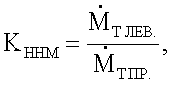
где
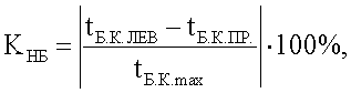
коэффициент КНБ определяется по формуле
где tБ.К.ЛЕВ. - время блокирования левого колеса,
tБ.К.ПР., - время блокирования правого колеса,
tБ.к.max, - наибольшее время блокирования колеса;
момент МРАЗВ определяется по формуле
МРАЗВ=(RХ ЛЕВ.-RХ ПР.)·BA,
где RХ ЛЕВ. и RХ ПР. - продольные реакции на левом и правом колесах одной оси автотранспортного средства соответственно, а ВA - колея автомобиля. A test bench for diagnosing motor vehicle brakes, comprising two longitudinally movable bearings with a horizontal contact surface for mounting the wheels of the axle under test, a drive of bearings made on the basis of a power cylinder, ball guides for moving the movable bearings in the longitudinal direction, characterized in that the movable bearings do not have a rigid connection with each other and are set in motion separately by two independent power cylinders from one common pneumatic or hydraulic system, there is a device that signals the beginning of the movement of the moving supports, there is a device for determining the force on the brake pedal and its automatic drive, the horizontal contact surface of the moving supports has a polymer coating with an adhesion coefficient of at least 0.8, weight sensors are installed on each movable support, the start of movement and forces, the signals from which through an amplifier and an analog-to-digital converter are sent to a computer for processing, which gives the diagnostic results to a printing device and monitor screen brakes of each wheel, while the diagnostics of motor vehicle brakes is carried out taking into account the coefficient of non-uniformity of the increase in braking torque K NNM , the coefficient of non-uniformity of blocking the wheels of one axis in time K NB and the unfolding moment M DEVELOPMENT. characterizing the stability of the vehicle during braking,
while K NNM is determined by the formula
Where
the coefficient K NB is determined by the formula
where t B.K. LEV. - blocking time of the left wheel,
t B.K. , - blocking time of the right wheel,
t B.к.max , is the longest time of blocking the wheel;
moment M DEVELOPMENT is determined by the formula
M DEVELOPMENT = (R X LEFT. -R X PR. ) · B A ,
where R X LION. and R X PR. - longitudinal reactions on the left and right wheels of one axis of the vehicle, respectively, and B A is the track of the car.
Priority Applications (1)
| Application Number | Priority Date | Filing Date | Title |
|---|---|---|---|
| RU2008139838/11A RU2391237C1 (en) | 2008-10-07 | 2008-10-07 | Osipov test bench for vehicle brakes diagnostics |
Applications Claiming Priority (1)
| Application Number | Priority Date | Filing Date | Title |
|---|---|---|---|
| RU2008139838/11A RU2391237C1 (en) | 2008-10-07 | 2008-10-07 | Osipov test bench for vehicle brakes diagnostics |
Publications (2)
| Publication Number | Publication Date |
|---|---|
| RU2008139838A RU2008139838A (en) | 2010-04-20 |
| RU2391237C1 true RU2391237C1 (en) | 2010-06-10 |
Family
ID=42681466
Family Applications (1)
| Application Number | Title | Priority Date | Filing Date |
|---|---|---|---|
| RU2008139838/11A RU2391237C1 (en) | 2008-10-07 | 2008-10-07 | Osipov test bench for vehicle brakes diagnostics |
Country Status (1)
| Country | Link |
|---|---|
| RU (1) | RU2391237C1 (en) |
Cited By (5)
| Publication number | Priority date | Publication date | Assignee | Title |
|---|---|---|---|---|
| RU2456184C1 (en) * | 2011-02-14 | 2012-07-20 | Государственное образовательное учреждение высшего профессионального образования "Оренбургский государственный университет" | Mobile towed test bench for diagnostics, adjustments, repair and assembly of automotive wheel brakes |
| RU2545531C1 (en) * | 2014-01-09 | 2015-04-10 | Федеральное государственное бюджетное образовательное учреждение высшего профессионального образования "Иркутский государственный технический университет" (ФГБОУ ВПО "ИрГТУ") | Upgraded test bench by osipov for diagnostics of vehicle brake |
| EA037394B1 (en) * | 2015-04-07 | 2021-03-24 | Белорусский Национальный Технический Университет | Anti-lock braking system diagnostic stand |
| RU209319U1 (en) * | 2021-10-04 | 2022-03-15 | Александр Николаевич Русских | STAND FOR DIAGNOSTICS OF BRAKES OF VEHICLES |
| RU2783553C1 (en) * | 2022-02-12 | 2022-11-14 | Игорь Михайлович Блянкинштейн | Stand for testing the braking qualities and suspension elements of automobiles |
Citations (5)
| Publication number | Priority date | Publication date | Assignee | Title |
|---|---|---|---|---|
| EP0280785A2 (en) * | 1987-02-06 | 1988-09-07 | Rheinisch-Westfälischer Technischer Überwachungs-Verein e.V. | Test bench for motor vehicle brakes, in particular for passenger cars with an ABS device |
| US5495753A (en) * | 1991-04-02 | 1996-03-05 | Honda Giken Kogyo Kabushiki Kaisha | Apparatus and method of testing anti-lock brake system |
| US6247357B1 (en) * | 1993-08-30 | 2001-06-19 | Clayton Industries | Dynamometer for simulating the inertial and road load forces encountered by motor vehicles and method |
| RU2297932C1 (en) * | 2005-12-14 | 2007-04-27 | Государственное образовательное учреждение высшего профессионального образования "Иркутский государственный технический университет" (ГОУ ИрГТУ) | Methods of diagnosing condition of brake system of automobile furnished with antilocking system (versions); method of and device for diagnosing condition of automobile brake system |
| RU2323841C1 (en) * | 2006-07-06 | 2008-05-10 | Владимир Алексеевич Рогов | Test bench for automobile brakes |
-
2008
- 2008-10-07 RU RU2008139838/11A patent/RU2391237C1/en not_active IP Right Cessation
Patent Citations (5)
| Publication number | Priority date | Publication date | Assignee | Title |
|---|---|---|---|---|
| EP0280785A2 (en) * | 1987-02-06 | 1988-09-07 | Rheinisch-Westfälischer Technischer Überwachungs-Verein e.V. | Test bench for motor vehicle brakes, in particular for passenger cars with an ABS device |
| US5495753A (en) * | 1991-04-02 | 1996-03-05 | Honda Giken Kogyo Kabushiki Kaisha | Apparatus and method of testing anti-lock brake system |
| US6247357B1 (en) * | 1993-08-30 | 2001-06-19 | Clayton Industries | Dynamometer for simulating the inertial and road load forces encountered by motor vehicles and method |
| RU2297932C1 (en) * | 2005-12-14 | 2007-04-27 | Государственное образовательное учреждение высшего профессионального образования "Иркутский государственный технический университет" (ГОУ ИрГТУ) | Methods of diagnosing condition of brake system of automobile furnished with antilocking system (versions); method of and device for diagnosing condition of automobile brake system |
| RU2323841C1 (en) * | 2006-07-06 | 2008-05-10 | Владимир Алексеевич Рогов | Test bench for automobile brakes |
Cited By (6)
| Publication number | Priority date | Publication date | Assignee | Title |
|---|---|---|---|---|
| RU2456184C1 (en) * | 2011-02-14 | 2012-07-20 | Государственное образовательное учреждение высшего профессионального образования "Оренбургский государственный университет" | Mobile towed test bench for diagnostics, adjustments, repair and assembly of automotive wheel brakes |
| RU2545531C1 (en) * | 2014-01-09 | 2015-04-10 | Федеральное государственное бюджетное образовательное учреждение высшего профессионального образования "Иркутский государственный технический университет" (ФГБОУ ВПО "ИрГТУ") | Upgraded test bench by osipov for diagnostics of vehicle brake |
| EA037394B1 (en) * | 2015-04-07 | 2021-03-24 | Белорусский Национальный Технический Университет | Anti-lock braking system diagnostic stand |
| RU209319U1 (en) * | 2021-10-04 | 2022-03-15 | Александр Николаевич Русских | STAND FOR DIAGNOSTICS OF BRAKES OF VEHICLES |
| RU2783553C1 (en) * | 2022-02-12 | 2022-11-14 | Игорь Михайлович Блянкинштейн | Stand for testing the braking qualities and suspension elements of automobiles |
| RU2818702C1 (en) * | 2023-10-17 | 2024-05-03 | федеральное государственное бюджетное образовательное учреждение высшего образования "Санкт-Петербургский горный университет императрицы Екатерины II" | Brake roller test bench |
Also Published As
| Publication number | Publication date |
|---|---|
| RU2008139838A (en) | 2010-04-20 |
Similar Documents
| Publication | Publication Date | Title |
|---|---|---|
| CN102004039B (en) | Test jack horse and test method of electric vehicle electromagnetic and frictional brake integrated system | |
| US7493805B2 (en) | Apparatus and method for testing the performance of a vehicle | |
| RU2391237C1 (en) | Osipov test bench for vehicle brakes diagnostics | |
| CN101666714B (en) | Automobile dynamics test bed with transverse loading function | |
| CN108225666B (en) | A verification device for a flat brake test platform | |
| RU2545531C1 (en) | Upgraded test bench by osipov for diagnostics of vehicle brake | |
| RU2584641C1 (en) | Osipov universal bench for diagnosis of brakes and suspension of vehicle | |
| CN117109942B (en) | Fork truck testboard | |
| RU2333118C1 (en) | Device controlling motor vehicle braking efficiency (versions) | |
| CN103105299A (en) | Axle weight and brake and vehicle speed combined test bench | |
| RU2297932C1 (en) | Methods of diagnosing condition of brake system of automobile furnished with antilocking system (versions); method of and device for diagnosing condition of automobile brake system | |
| CN106153355B (en) | A kind of ramp abs braking testing stand | |
| CN104819853B (en) | A kind of anti-force type drum braking check-out console apparatus capable of fluctuating | |
| RU117375U1 (en) | STAND FOR DIAGNOSTIC OF THE BRAKE SYSTEM OF THE CAR | |
| KR100916214B1 (en) | Car inspection equipment | |
| CN205826312U (en) | A kind of bicycle brake force test system test platform | |
| CN108680362B (en) | A verification method of a flat plate brake test platform | |
| CN108414241B (en) | A flat-plate brake test platform calibration device and calibration method | |
| RU126294U1 (en) | MOBILE STAND FOR EXPRESS DIAGNOSTICS OF BRAKE MECHANISMS OF PASSENGER VEHICLES | |
| CN110849641A (en) | Bogie load test method | |
| RU2411145C1 (en) | Automotive brake system test bench | |
| CN211504520U (en) | Calibrating device for flat plate type brake inspection platform | |
| CN212059370U (en) | Flat braking test platform calibrating installation | |
| RU2613076C1 (en) | Testing bench for vehicle brake diagnosis | |
| RU2375218C1 (en) | Method of dynamic diagnozing automotive anti-skidding systems and device to this end |
Legal Events
| Date | Code | Title | Description |
|---|---|---|---|
| MM4A | The patent is invalid due to non-payment of fees |
Effective date: 20111008 |