Предлагаемое изобретение относится к области рельсовых транспортных средств и может быть использовано в конструкции пассажирских и грузовых вагонов.The present invention relates to the field of rail vehicles and can be used in the construction of passenger and freight cars.
Известна колесная пара, составляющая конструкцию ходовых частей грузовых и пассажирских вагонов (см. Технический справочник железнодорожника. Том 6 Подвижной состав. Государственное транспортное железнодорожное издательство. Москва, 1952. Стр.595, фиг.45), состоящая из оси и двух колес цельных или сборных. Цельные и сборные колеса снабжены гребнями, предназначенными для удержания колесной пары в движении на рельсах рельсовой колеи. Несмотря на свою эффективность использования, такие колесные пары обладают существенным недостатком, заключающимся в том, что при некотором уширении рельсовой колеи, выше допускаемых пределов, возможен сход подвижного состава. В то же время при сужении колеи за счет возникновения значительных по величине сил трения между гребнем и головкой рельса, происходит повышенный износ указанной кинематической пары. Поэтому в практике как в первом, так и во втором случае из-за возможного схода вагонов ОАО «РЖД» несет значительные затраты как материальные, так и трудовые, связанные с ликвидацией аварий подвижного состава, а также с преждевременным восстановительным ремонтом колесных пар.A wheelset is known that makes up the chassis of freight and passenger cars (see Technical Guide for Railway Workers. Volume 6 Rolling Stock. State Transport Railway Publishing House. Moscow, 1952. Page 555, Fig. 45), consisting of an axle and two solid wheels national teams. Solid and prefabricated wheels are provided with ridges designed to keep the wheelset in motion on rails of the rail track. Despite their efficiency of use, such wheelsets have a significant drawback, namely, that with a certain broadening of the rail track, above the permissible limits, rolling stock is possible. At the same time, when the track is narrowed due to the occurrence of significant friction forces between the ridge and the rail head, increased wear of the specified kinematic pair occurs. Therefore, in practice, both in the first and in the second case, due to the possible departure of cars, Russian Railways incurs significant material and labor costs associated with the liquidation of rolling stock accidents, as well as with premature restoration of wheel sets.
Известна также колесная пара, описанная и показанная в книге Железнодорожный транспорт. Энциклопедия / гл. ред. Н.С.Конарев М.: Большая российская энциклопедия, 1994, стр.186. Конструкция такой колесной пары в целом аналогична вышеописанной и поэтому недостатки их подобны.A wheelset is also known, described and shown in the book Railway Transport. Encyclopedia / Ch. ed. N.S. Konarev M .: Big Russian Encyclopedia, 1994, p.186. The design of such a pair of wheels is generally similar to that described above and therefore their disadvantages are similar.
Поэтому целью предлагаемого изобретения является снижение вероятности схода подвижного состава и увеличение срока службы гребней колес колесных пар.Therefore, the aim of the invention is to reduce the likelihood of rolling stock and increase the service life of wheel flanges.
Поставленная цель достигается тем, что на оси колесной пары, в пространстве между колесами, подвижно, в продольной ее плоскости, размещена пара подпружиненных между собой пружиной сжатия втулок с жестко присоединенными к их торцам дисками, круговые образующие поверхности которых имеют форму гребней цельнокатаных колес.This goal is achieved by the fact that on the axis of the wheelset, in the space between the wheels, movably, in its longitudinal plane, there is a pair of spring-loaded bushes with a compression spring with disks rigidly attached to their ends, the circular forming surfaces of which have the shape of flanges of seamless-rolled wheels.
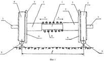
На фиг.1 показан общий вид колесной пары, а на фиг.2 - укрупненный вид одного из ее колес.Figure 1 shows a General view of the wheelset, and figure 2 is an enlarged view of one of its wheels.
Колесная пара вагона состоит из оси 1 с подступичной частью 2 и шейкой 3. На оси 1 жестко закреплено цельнокатаное колесо 4, к которому примыкает гребень 5, выполненный на круговых поверхностях дисков 6, жестко присоединенных к втулкам 7, подвижно установленным на оси 1. Втулки 7 подпружинены относительно друг друга пружиной сжатия 8. Цельнокатаное колесо 4 расположено на рельсах 9.The wagon’s wheelset consists of an axis 1 with an inlet part 2 and a neck 3. A solid-rolled wheel 4 is rigidly fixed to the axis 1, to which a ridge 5 is adjacent, made on the circular surfaces of the disks 6, rigidly attached to the bushings 7, movably mounted on the axis 1. Bushings 7 are spring-loaded relative to each other by a compression spring 8. The seamless-rolled wheel 4 is located on the rails 9.
Работает колесная пара следующим образом. При взаимодействии колесной пары с рельсами 9, образующими колею шириной l (см. фиг.1) соответствующую, например, принятому в нашей стране стандарту 1520 мм с допуском ±4 мм, гребни 5 находятся в контакте с головками рельс 9, при этом зазор Δ (см. фиг.1) равен нулю, а зазор S, образованный гребнем 5 и цельнокатаным колесом 4, в практике может составлять порядка 20 мм. Указанные зазоры обусловлены тем, что между втулками 7, жестко присоединенными к дискам 6 с гребнями 5, установлена предварительно сжатая пружина сжатия 8, которая удерживает указанные детали, действуя на них по стрелкам А. При движении вагона по перегонам или станционным путям возможно изменение ширины колени l в сторону уширения или сужения. Тогда в первом случае появится зазор Δ, который тут же будет ликвидирован за счет того, что пружина сжатия 8 переместит втулку 7 по оси 1 также в направлении стрелки А. Если же произойдет сужение рельсовой колеи, т.е. уменьшение размера l, то под действием реакции рельса гребень 5 совместно с диском 6 и втулкой 7 переместится в направлении, противоположном стрелке А, сжав при этом пружину сжатия 8. Указанные перемещения гребней 5 как левого, так и правого цельнокатаных колес 4 будут постоянно обеспечивать величину зазора Δ, равную нулю, т.е. в любом случае будут контактироваться с головками рельс 9, исключая тем самым сход вагона с рельсов и обеспечивая при этом плавность хода его в процессе движения с различными скоростями.The wheelset works as follows. When the pair of wheels interacts with rails 9, forming a track of width l (see figure 1) corresponding, for example, to the standard of 1520 mm accepted in our country with a tolerance of ± 4 mm, ridges 5 are in contact with the heads of the rail 9, with a gap Δ (see figure 1) is equal to zero, and the gap S formed by the ridge 5 and the solid-rolled wheel 4, in practice, can be about 20 mm. These gaps are due to the fact that between the bushings 7, rigidly attached to the disks 6 with ridges 5, a precompressed compression spring 8 is installed, which holds these parts, acting on them along arrows A. When the car moves along the tracks or station tracks, the knee width may change l towards broadening or narrowing. Then, in the first case, a gap Δ will appear, which will be immediately eliminated due to the fact that the compression spring 8 moves the sleeve 7 along the axis 1 also in the direction of arrow A. If the rail track becomes narrower, i.e. size l, then under the reaction of the rail, the ridge 5 together with the disk 6 and the sleeve 7 will move in the opposite direction to arrow A, compressing the compression spring 8. The indicated movements of the ridges 5 of both the left and right solid-rolled wheels 4 will constantly provide the value a gap Δ equal to zero, i.e. in any case, they will be in contact with the heads of the rail 9, thereby excluding the wagon coming off the rails and, at the same time, ensuring its smooth running during movement at different speeds.
Технико-экономическое преимущество предложенного технического решения в сравнении с известными очевидно, т.к. повышается безопасность движения вагонов и их плавность хода.The technical and economic advantage of the proposed technical solution in comparison with the known ones is obvious, because increases the safety of movement of cars and their smoothness.