RU2420002C2 - Portable communication device with improved possibility of special connection - Google Patents
Portable communication device with improved possibility of special connection Download PDFInfo
- Publication number
- RU2420002C2 RU2420002C2 RU2009123975/09A RU2009123975A RU2420002C2 RU 2420002 C2 RU2420002 C2 RU 2420002C2 RU 2009123975/09 A RU2009123975/09 A RU 2009123975/09A RU 2009123975 A RU2009123975 A RU 2009123975A RU 2420002 C2 RU2420002 C2 RU 2420002C2
- Authority
- RU
- Russia
- Prior art keywords
- communication
- directional communication
- wifi
- short
- devices
- Prior art date
Links
- 238000004891 communication Methods 0.000 title claims abstract description 96
- 238000000034 method Methods 0.000 claims abstract description 34
- 230000004913 activation Effects 0.000 claims abstract description 11
- 230000003213 activating effect Effects 0.000 claims description 9
- 238000001454 recorded image Methods 0.000 claims description 8
- 238000001514 detection method Methods 0.000 claims description 5
- 238000005516 engineering process Methods 0.000 abstract description 13
- 239000000126 substance Substances 0.000 abstract 1
- 230000001413 cellular effect Effects 0.000 description 36
- 238000005259 measurement Methods 0.000 description 16
- 230000005540 biological transmission Effects 0.000 description 11
- 230000006870 function Effects 0.000 description 10
- 238000012545 processing Methods 0.000 description 7
- 238000003825 pressing Methods 0.000 description 5
- 230000009467 reduction Effects 0.000 description 5
- 230000009471 action Effects 0.000 description 3
- 230000005670 electromagnetic radiation Effects 0.000 description 3
- 230000008569 process Effects 0.000 description 3
- 238000000060 site-specific infrared dichroism spectroscopy Methods 0.000 description 3
- 230000008901 benefit Effects 0.000 description 2
- 238000004590 computer program Methods 0.000 description 2
- 230000007423 decrease Effects 0.000 description 2
- 238000010586 diagram Methods 0.000 description 2
- 239000011159 matrix material Substances 0.000 description 2
- 238000007476 Maximum Likelihood Methods 0.000 description 1
- 239000003990 capacitor Substances 0.000 description 1
- 238000001444 catalytic combustion detection Methods 0.000 description 1
- 238000012544 monitoring process Methods 0.000 description 1
- 230000010363 phase shift Effects 0.000 description 1
- 239000004065 semiconductor Substances 0.000 description 1
- 230000035945 sensitivity Effects 0.000 description 1
- 230000008054 signal transmission Effects 0.000 description 1
- 238000012546 transfer Methods 0.000 description 1
- 238000002604 ultrasonography Methods 0.000 description 1
Images


Classifications
-
- H—ELECTRICITY
- H04—ELECTRIC COMMUNICATION TECHNIQUE
- H04W—WIRELESS COMMUNICATION NETWORKS
- H04W48/00—Access restriction; Network selection; Access point selection
- H04W48/08—Access restriction or access information delivery, e.g. discovery data delivery
- H04W48/10—Access restriction or access information delivery, e.g. discovery data delivery using broadcasted information
-
- H—ELECTRICITY
- H04—ELECTRIC COMMUNICATION TECHNIQUE
- H04B—TRANSMISSION
- H04B7/00—Radio transmission systems, i.e. using radiation field
- H04B7/02—Diversity systems; Multi-antenna system, i.e. transmission or reception using multiple antennas
- H04B7/04—Diversity systems; Multi-antenna system, i.e. transmission or reception using multiple antennas using two or more spaced independent antennas
- H04B7/06—Diversity systems; Multi-antenna system, i.e. transmission or reception using multiple antennas using two or more spaced independent antennas at the transmitting station
- H04B7/0602—Diversity systems; Multi-antenna system, i.e. transmission or reception using multiple antennas using two or more spaced independent antennas at the transmitting station using antenna switching
-
- H—ELECTRICITY
- H04—ELECTRIC COMMUNICATION TECHNIQUE
- H04B—TRANSMISSION
- H04B7/00—Radio transmission systems, i.e. using radiation field
- H04B7/14—Relay systems
- H04B7/15—Active relay systems
- H04B7/155—Ground-based stations
- H04B7/15528—Control of operation parameters of a relay station to exploit the physical medium
- H04B7/1555—Selecting relay station antenna mode, e.g. selecting omnidirectional -, directional beams, selecting polarizations
-
- H—ELECTRICITY
- H04—ELECTRIC COMMUNICATION TECHNIQUE
- H04N—PICTORIAL COMMUNICATION, e.g. TELEVISION
- H04N23/00—Cameras or camera modules comprising electronic image sensors; Control thereof
- H04N23/60—Control of cameras or camera modules
- H04N23/63—Control of cameras or camera modules by using electronic viewfinders
-
- H—ELECTRICITY
- H04—ELECTRIC COMMUNICATION TECHNIQUE
- H04W—WIRELESS COMMUNICATION NETWORKS
- H04W8/00—Network data management
- H04W8/005—Discovery of network devices, e.g. terminals
-
- H—ELECTRICITY
- H04—ELECTRIC COMMUNICATION TECHNIQUE
- H04W—WIRELESS COMMUNICATION NETWORKS
- H04W84/00—Network topologies
- H04W84/18—Self-organising networks, e.g. ad-hoc networks or sensor networks
Landscapes
- Engineering & Computer Science (AREA)
- Signal Processing (AREA)
- Computer Networks & Wireless Communication (AREA)
- Databases & Information Systems (AREA)
- Multimedia (AREA)
- Computer Security & Cryptography (AREA)
- Mobile Radio Communication Systems (AREA)
- Studio Devices (AREA)
- Telephone Function (AREA)
- Transceivers (AREA)
Abstract
Description
Область техники, к которой относится изобретениеFIELD OF THE INVENTION
Настоящее изобретение относится к области портативных устройств связи, а более конкретно, но не только, к портативным устройствам связи, снабженным возможностями связи в коротком диапазоне для специальной связи.The present invention relates to the field of portable communication devices, and more specifically, but not only to portable communication devices equipped with short-range communication capabilities for special communications.
Уровень техникиState of the art
Сегодня существует тенденция в области портативных устройств к наделению этих устройств все более разнообразными функциями. В частности, существует тенденция обеспечения портативных устройств улучшенной возможностью управлять мультимедийными элементами данных, такими как различные звуки, изображения и видео и т.д. Звуками, например, может быть музыка или т.п., изображениями могут быть фотографии или т.п., а видео может быть фильм или т.п. Мультимедийные элементы данных могут быть записаны или загружены посредством портативного устройства. Подобным образом, с возрастающей скоростью различные игровые и развлекательные элементы внедряются в портативные устройства.Today, there is a trend in the field of portable devices to give these devices more and more diverse functions. In particular, there is a tendency to provide portable devices with improved ability to control multimedia data elements such as various sounds, images and videos, etc. Sounds, for example, may be music or the like, images may be photographs or the like, and video may be a movie or the like. Multimedia data elements can be recorded or downloaded via a portable device. Similarly, with increasing speed, various gaming and entertainment elements are being incorporated into portable devices.
Так как портативные устройства стали более "разумными" и похожими на стационарные устройства, потребность обмена мультимедийными элементами между разными устройствами становится все более и более востребованной и необходимой. Например, пользователь может хотеть посмотреть фильм на домашнем телевизоре или послушать музыкальную пьесу на домашней Hi-Fi-системе, также как и насладиться этими элементами на портативном устройстве. В другой ситуации пользователь может хотеть представить изображения или видео, записанные портативным устройством. Тогда будет полезно, если эти изображения и видеоряды могут быть легко перенесены на телевизионный приемник или устройство, соединенное с телевизионным приемником, для предоставления более крупного монитора, которым могут наслаждаться несколько зрителей. Может также возникнуть потребность в сохранении изображений или видео, записанных портативным устройством, в стационарном запоминающем устройстве, имеющем больший объем памяти. Опять же, будет полезно, если изображения и/или видеоряды могут быть легко перенесены в стационарное запоминающее устройство. В целом, существует множество ситуаций, в которых будет полезным переносить мультимедийные элементы данных и развлекательные элементы данных между различными устройствами.Since portable devices have become more “intelligent” and similar to stationary devices, the need for the exchange of multimedia elements between different devices is becoming more and more popular and necessary. For example, a user may want to watch a movie on a home TV or listen to a piece of music on a home Hi-Fi system, as well as enjoy these elements on a portable device. In another situation, the user may want to present images or videos recorded by the portable device. Then it will be useful if these images and video sequences can be easily transferred to a television receiver or device connected to a television receiver to provide a larger monitor that several viewers can enjoy. There may also be a need to store images or videos recorded by the portable device in a stationary storage device having a larger amount of memory. Again, it will be useful if images and / or video sequences can be easily transferred to a stationary storage device. In general, there are many situations in which it will be useful to transfer multimedia data elements and entertainment data elements between different devices.
Хорошо известной и обычно используемой технологией для простого переноса мультимедийных и развлекательных элементов между различными устройствами являются так называемые беспроводные локальные вычислительные сети (WLAN), а в особенности, так называемая WiFi-технология. WiFi (также известная как Wi-Fi, wifi и т.д.) является торговой маркой, которая была изначально лицензирована альянсом WiFi, чтобы описать лежащую в основе технологию WLAN на базе спецификаций IEEE 802.11 или т.п. Человек с WiFi-устройством, таким как сотовый телефон или PDA или т.п., может, например, соединяться с Интернетом, когда находится вблизи точки доступа. Пространство, покрываемое одной или несколькими точками доступа, называется "горячей" точкой (хотспот - hotspot). WiFi также предоставляет возможность связи в одноранговом режиме, который разрешает устройствам соединяться непосредственно друг с другом. Этот режим связности является особенно полезным, например, в бытовой электронной аппаратуре и игровых приложениях и т.п.Well-known and commonly used technology for easily transferring multimedia and entertainment elements between different devices is the so-called wireless local area network (WLAN), and in particular, the so-called WiFi technology. WiFi (also known as Wi-Fi, wifi, etc.) is a trademark that was originally licensed by the WiFi alliance to describe the underlying WLAN technology based on IEEE 802.11 specifications or the like. A person with a WiFi device, such as a cell phone or PDA or the like, can, for example, connect to the Internet when it is near an access point. The space covered by one or more access points is called a hotspot (hotspot). WiFi also provides peer-to-peer connectivity, which allows devices to connect directly to each other. This connectivity mode is especially useful, for example, in consumer electronics and gaming applications, and the like.
Однако во многих домах и офисах и других густо заселенных районах будет несколько оборудованных WiFi устройств, и, таким образом, будут их соседи. Так как WiFi-устройства имеют скорее дальний диапазон действия, они будут иметь большую степень покрытия того же пространства. Проблема тогда состоит в том, как защитить простоту использования при соединении оснащенного WiFi портативного устройства с другим WiFi-устройством в окружении, в котором портативное устройство находит множество устройств (например, 5), расположенных в настоящей комнате, и даже больше (например, 15) устройств в WiFi-диапазоне, расположенных по соседству.However, in many homes and offices and other densely populated areas there will be several equipped WiFi devices, and thus their neighbors will be. Since WiFi devices are more likely to have a long range, they will have a greater degree of coverage for the same space. The problem then is how to protect ease of use when connecting a WiFi-equipped portable device to another WiFi device in an environment in which the portable device finds many devices (e.g. 5) located in this room, and even more (e.g. 15) devices in the WiFi range located in the neighborhood.
Согласно известным решениям пользователь и портативное устройство сканируют WiFi-устройства. Пользователь затем должен выбрать из длинного списка совместимых устройств в диапазоне действия, включающего в себя устройства, расположенные по соседству и т.д. С течением времени, пользователь может создать список избранных устройств, который может упростить выбор. Однако пользователь может остаться со слишком длинным списком избранных устройств дома, в офисе, в машине, в летнем домике и т.д., и преимущества списка избранных устройств уменьшаются.According to known solutions, the user and the portable device scan WiFi devices. The user must then select from a long list of compatible devices in the range of action, including devices located in the neighborhood, etc. Over time, the user can create a list of favorite devices, which can simplify the selection. However, the user may be left with a too long list of selected devices at home, in the office, in the car, in a summer house, etc., and the benefits of the list of favorite devices are reduced.
Принимая во внимание вышесказанное, будет полезно предоставить улучшенное беспроводное соединение портативного устройства с выбранным устройством в группе расположенных поблизости устройств. В отдельном аспекте будет полезно предоставить упомянутое улучшенное беспроводное соединение с помощью минимальной дополнительной схемы и обработки сигнала в портативном устройстве.In view of the foregoing, it will be useful to provide an improved wireless connection between the portable device and the selected device in a group of nearby devices. In a separate aspect, it will be useful to provide said improved wireless connection with minimal additional circuitry and signal processing in a portable device.
Раскрытие изобретенияDisclosure of invention
Настоящее изобретение направлено на решение проблемы предоставления улучшенного беспроводного соединения портативного устройства с выбранным устройством в группе расположенных поблизости устройств. Согласно отдельному аспекту будет полезно предоставить упомянутое улучшенное беспроводное соединение с помощью минимальной дополнительной схемы и обработки сигнала в портативном устройстве.The present invention seeks to solve the problem of providing an improved wireless connection of a portable device to a selected device in a group of nearby devices. According to a separate aspect, it will be useful to provide said improved wireless connection with a minimum of additional circuitry and signal processing in a portable device.
Одной целью настоящего изобретения, таким образом, является предоставление улучшенного беспроводного соединения портативного устройства с выбранным устройством в группе расположенных поблизости устройств.One objective of the present invention, therefore, is to provide an improved wireless connection of a portable device to a selected device in a group of nearby devices.
Эта цель достигается согласно первому аспекту настоящего изобретения, который предоставляет способ беспроводного соединения беспроводного портативного устройства с выбранным беспроводным устройством в группе расположенных поблизости беспроводных устройств, причем это портативное устройство снабжено блоком малого радиуса действия беспроводной связи с упомянутой группой расположенных поблизости беспроводных устройств, по существу, всенаправленной антенной, соединенной с упомянутым блоком малого радиуса действия для, по существу, всенаправленной связи, и, по меньшей мере, одним устройством направленной связи, соединенным с упомянутым блоком малого радиуса действия для, по существу, направленной связи.This goal is achieved according to the first aspect of the present invention, which provides a method for wirelessly connecting a wireless portable device to a selected wireless device in a group of nearby wireless devices, this portable device having a short-range wireless unit with said group of nearby wireless devices, essentially an omnidirectional antenna connected to said short-range unit for essentially omnidirectional communication, and at least one directional communication device connected to said short-range unit for essentially directional communication.
Способ содержит этапы:The method comprises the steps of:
- активации устройства направленной связи,- activation of a directional communication device,
- направления устройства направленной связи на расположенное поблизости беспроводное устройство,- directing the directional communication device to a nearby wireless device,
- соединения портативного устройства с выбранным устройством посредством устройства направленной связи,- connecting the portable device to the selected device through a directional communication device,
- связи с выбранным устройством через упомянутую, по существу, всенаправленную антенну после упомянутого соединения.- communication with the selected device through said essentially omnidirectional antenna after said connection.
Второй аспект изобретения направлен на способ, включающий в себя признаки первого аспекта, отличающийся использованием направленной антенны, соединенной с упомянутым блоком малого радиуса действия в качестве устройства направленной связи, для направленной связи посредством электромагнитного излучения.The second aspect of the invention is directed to a method including the features of the first aspect, characterized in using a directional antenna connected to said short-range unit as a directional communication device for directional communication by means of electromagnetic radiation.
Третий аспект изобретения направлен на способ, включающий в себя признаки первого и второго аспекта, отличающийся, по меньшей мере, использованием камеры, содержащейся в портативном устройстве связи, в качестве устройства направленной связи для направленной связи посредством записи информации, принятой посредством света.A third aspect of the invention is directed to a method including the features of the first and second aspects, characterized by at least using a camera contained in a portable communication device as a directional communication device for directional communication by recording information received by light.
Четвертый аспект изобретения направлен на способ, включающий в себя признаки третьего аспекта, отличающийся использованием камеры для направленной связи посредством записи света, излученного от выбранного устройства, причем этот свет используется портативным устройством, чтобы идентифицировать выбранное устройство.A fourth aspect of the invention is directed to a method including features of a third aspect, characterized by using a camera for directional communication by recording the light emitted from the selected device, this light being used by the portable device to identify the selected device.
Пятый аспект изобретения направлен на способ, включающий в себя признаки третьего аспекта, отличающийся использованием камеры (24) для направленной связи посредством записи изображения выбранного устройства (10a), причем это изображение используется портативным устройством (10), чтобы идентифицировать выбранное устройство (10a).A fifth aspect of the invention is directed to a method including features of a third aspect, characterized by using a camera (24) for directional communication by recording an image of a selected device (10a), this image being used by a portable device (10) to identify the selected device (10a).
Шестой аспект изобретения направлен на способ, включающий в себя признаки пятого аспекта, отличающийся этапами извлечения любой полезной для соединения информации из возможных меток в записанном изображении.The sixth aspect of the invention is directed to a method that includes the features of the fifth aspect, characterized by the steps of extracting any information useful for joining from possible marks in the recorded image.
Седьмой аспект изобретения направлен на способ, включающий в себя признаки первого аспекта, отличающийся тем, что устройство направленной связи активируется при происшествии, по меньшей мере, одного из следующего: пользователь нажимает клавишу на клавиатуре портативного устройства; обнаружение нескольких расположенных поблизости устройств; активация прикладной программы.The seventh aspect of the invention is directed to a method that includes the features of the first aspect, characterized in that the directional communication device is activated when at least one of the following occurs: the user presses a key on the keyboard of the portable device; detection of several nearby devices; application activation.
Восьмой аспект изобретения направлен на способ, включающий в себя признаки второго аспекта, отличающийся этапами:The eighth aspect of the invention is directed to a method that includes the features of the second aspect, characterized in stages:
- активации всенаправленной антенны и выполнения измерения уровней сигнала от расположенных поблизости устройств,- activating an omnidirectional antenna and measuring signal levels from nearby devices,
- активации направленной антенны и выполнения измерения уровня сигнала, по меньшей мере, от одного расположенного поблизости устройства, когда направленная антенна направлена к расположенному поблизости устройству,- activating a directional antenna and performing a signal level measurement from at least one nearby device when the directional antenna is directed to a nearby device,
- соединения портативного устройства с расположенным поблизости устройством, имеющим, по существу, одинаковый уровень сигнала во всенаправленном измерении и в направленном измерении, или имеющим более высокий уровень сигнала в направленном измерении.- connecting the portable device to a nearby device having substantially the same signal level in the omnidirectional measurement and in the directional measurement, or having a higher signal level in the directional measurement.
Девятый аспект изобретения направлен на способ, включающий в себя признаки второго аспекта, отличающийся этапами:The ninth aspect of the invention is directed to a method that includes the features of the second aspect, characterized in stages:
- активации всенаправленной антенны и выполнения измерения уровней сигнала от расположенных поблизости устройств,- activating an omnidirectional antenna and measuring signal levels from nearby devices,
- активации направленной антенны и выполнения измерения уровня сигнала, по меньшей мере, от одного расположенного поблизости устройства, когда направленная антенна направлена к расположенному поблизости устройству,- activating a directional antenna and performing a signal level measurement from at least one nearby device when the directional antenna is directed to a nearby device,
- соединения портативного устройства с расположенным поблизости устройством, имеющим самую низкую степень уменьшения в уровне сигнала от всенаправленного измерения до направленного измерения.- connecting a portable device to a nearby device having the lowest degree of reduction in signal level from omnidirectional measurement to directional measurement.
Десятый аспект изобретения направлен на способ, включающий в себя признаки второго, восьмого или девятого аспекта, отличающийся тем, что мощность передачи уменьшается, когда активируется направленная антенна.A tenth aspect of the invention is directed to a method including features of a second, eighth or ninth aspect, characterized in that the transmit power decreases when a directional antenna is activated.
Цель, упомянутая выше, также достигается согласно одиннадцатому аспекту настоящего изобретения, направленному на беспроводное портативное устройство, выполненное с возможностью функционального соединения с выбранным беспроводным устройством в группе расположенных поблизости беспроводных устройств, причем это портативное устройство содержит блок малого радиуса действия для беспроводной связи с упомянутой группой расположенных поблизости беспроводных устройств и, по существу, всенаправленную антенну, соединенную с упомянутым блоком малого радиуса действия для, по существу, всенаправленной связи с упомянутыми расположенными поблизости беспроводными устройствами.The goal mentioned above is also achieved according to the eleventh aspect of the present invention, directed to a wireless portable device configured to functionally connect with a selected wireless device in a group of nearby wireless devices, this portable device comprising a short-range unit for wireless communication with said group nearby wireless devices and a substantially omnidirectional antenna connected to said unit th short-range for a substantially omni-directional communication with said by nearby wireless devices.
Портативное устройство дополнительно содержит: по меньшей мере, одно устройство направленной связи, соединенное с упомянутым блоком малого радиуса действия и выполненное с возможностью оперативного направления на расположенное поблизости беспроводное устройство и оперативного обмена информацией о соединении с выбранным устройством, когда устройство направленной связи направлено на упомянутое расположенное поблизости устройство.The portable device further comprises: at least one directional communication device connected to said short-range unit and configured to operatively direct a nearby wireless device and exchange information about the connection with the selected device when the directional communication device is directed to said located nearby device.
Двенадцатый аспект изобретения направлен на портативное устройство, включающее в себя признаки одиннадцатого аспекта, отличающееся тем, что устройство направленной связи является направленной антенной, соединенной с упомянутым блоком малого радиуса действия, для направленной связи посредством электромагнитного излучения.The twelfth aspect of the invention is directed to a portable device including the features of the eleventh aspect, characterized in that the directional communication device is a directional antenna connected to said short-range unit for directional communication by electromagnetic radiation.
Тринадцатый аспект изобретения направлен на портативное устройство, включающее в себя признаки одиннадцатого или двенадцатого аспекта, отличающееся тем, что устройство направленной связи является камерой, содержащейся в портативном устройстве связи, для связи посредством записи информации, принятой посредством света.The thirteenth aspect of the invention is directed to a portable device including the features of the eleventh or twelfth aspect, characterized in that the directional communication device is a camera contained in a portable communication device for communication by recording information received by light.
Четырнадцатый аспект изобретения направлен на портативное устройство, включающее в себя признаки тринадцатого аспекта, отличающееся тем, что камера выполнена с возможностью направленной связи посредством записи света, излученного выбранным беспроводным устройством, и тем, что портативное устройство выполнено с возможностью использования принятого света, чтобы идентифицировать выбранное устройство.A fourteenth aspect of the invention is directed to a portable device including features of the thirteenth aspect, characterized in that the camera is capable of directional communication by recording the light emitted by the selected wireless device, and that the portable device is configured to use the received light to identify the selected device.
Пятнадцатый аспект изобретения направлен на портативное устройство, включающее в себя признаки тринадцатого аспекта, характеризуемое тем, что камера выполнена с возможностью направленной связи посредством записи изображения выбранного беспроводного устройства, и тем, что портативное устройство выполнено с возможностью использования изображения, чтобы идентифицировать выбранное устройство.A fifteenth aspect of the invention is directed to a portable device including features of the thirteenth aspect, characterized in that the camera is configured for directional communication by recording an image of a selected wireless device, and in that the portable device is adapted to use an image to identify a selected device.
Шестнадцатый аспект изобретения направлен на портативное устройство, включающее в себя признаки пятнадцатого аспекта, характеризуемое тем, что блок малого радиуса действия выполнен с возможностью оперативного извлечения любой полезной информации о соединении из возможных меток в записанном изображении.The sixteenth aspect of the invention is directed to a portable device including the features of the fifteenth aspect, characterized in that the short-range unit is operative to quickly retrieve any useful connection information from possible marks in the recorded image.
Семнадцатый аспект изобретения направлен на портативное устройство, включающее в себя признаки двенадцатого аспекта, отличающееся тем, что устройство направленной связи активируется при наступлении, по меньшей мере, одного из следующих событий: пользователь нажимает клавишу на клавиатуре портативного устройства; обнаружение нескольких расположенных поблизости устройств; активация прикладной программы.The seventeenth aspect of the invention is directed to a portable device including the features of the twelfth aspect, characterized in that the directional communication device is activated when at least one of the following events occurs: the user presses a key on the keyboard of the portable device; detection of several nearby devices; application activation.
Восемнадцатый аспект изобретения направлен на портативное устройство, включающее в себя признаки тринадцатого аспекта, отличающееся тем, что элемент управления малого радиуса действия выполнен с возможностью оперативно:The eighteenth aspect of the invention is directed to a portable device including the features of the thirteenth aspect, characterized in that the short-range control element is operative to:
- активировать всенаправленную антенну и выполнять измерение уровней сигнала от расположенных поблизости устройств,- activate an omnidirectional antenna and measure signal levels from nearby devices,
- активировать направленную антенну и выполнять измерение уровня сигнала, по меньшей мере, от одного расположенного поблизости устройства, когда направленная антенна направлена на расположенное поблизости устройство,- activate the directional antenna and measure the signal level from at least one nearby device when the directional antenna is directed to a nearby device,
- соединять портативное устройство с расположенным поблизости устройством, имеющим, по существу, такой же уровень сигнала во всенаправленном измерении и в направленном измерении, или имеющим более высокий уровень сигнала в направленном измерении.- connect the portable device to a nearby device having substantially the same signal level in the omnidirectional measurement and in the directional measurement, or having a higher signal level in the directional measurement.
Девятнадцатый аспект изобретения направлен на портативное устройство, включающее в себя признаки тринадцатого аспекта, отличающееся тем, что элемент управления малого радиуса действия выполнен с возможностью оперативно:The nineteenth aspect of the invention is directed to a portable device that includes the features of the thirteenth aspect, characterized in that the control element is short-range made with the ability to quickly:
- активировать всенаправленную антенну и выполнять измерение уровней сигнала от расположенных поблизости устройств,- activate an omnidirectional antenna and measure signal levels from nearby devices,
- активировать направленную антенну и выполнять измерение уровня сигнала, по меньшей мере, от одного расположенного поблизости устройства, когда направленная антенна направлена на расположенное поблизости устройство,- activate the directional antenna and measure the signal level from at least one nearby device when the directional antenna is directed to a nearby device,
- соединять портативное устройство с расположенным поблизости устройством, имеющим самую низкую степень уменьшения в уровне сигнала от всенаправленного измерения до направленного измерения.- connect the portable device to a nearby device having the lowest degree of reduction in signal level from omnidirectional measurement to directional measurement.
Двадцатый аспект изобретения направлен на портативное устройство, включающее в себя признаки тринадцатого аспекта, отличающееся тем, что элемент управления малого радиуса действия выполнен с возможностью оперативно уменьшать мощность передачи, когда направленная антенна активируется.A twentieth aspect of the invention is directed to a portable device including features of the thirteenth aspect, characterized in that the short-range control element is operative to rapidly reduce transmit power when the directional antenna is activated.
Двадцать первый аспект изобретения направлен на компьютерный программный продукт, сохраненный на машиночитаемом носителе, содержащий считываемое программное средство для инструктирования портативного устройства на выполнение, при загруженном упомянутом программном средстве в портативное устройство, содержащее:A twenty-first aspect of the invention is directed to a computer program product stored on a computer-readable medium, comprising readable software for instructing a portable device to execute, when said software is loaded into a portable device, comprising:
- блок малого радиуса действия для беспроводной связи с упомянутой группой расположенных поблизости устройств,- a short-range unit for wireless communication with said group of nearby devices,
- по существу, всенаправленную антенну, соединенную с упомянутым блоком малого радиуса действия для, по существу, всенаправленной связи, и- essentially an omnidirectional antenna connected to said short-range unit for essentially omnidirectional communication, and
- по меньшей мере, одно устройство направленной связи для направленной связи,at least one directional communication device for directional communication,
этапов:stages:
- активации устройства направленной связи,- activation of a directional communication device,
- соединения портативного устройства с выбранным устройством посредством устройства направленной связи, когда устройство направленной связи направлено на выбранное устройство,- connecting the portable device to the selected device through the directional communication device when the directional communication device is directed to the selected device,
- связи с выбранным устройством через упомянутую, по существу, всенаправленную антенну после упомянутого соединения.- communication with the selected device through said essentially omnidirectional antenna after said connection.
Двадцать второй аспект изобретения направлен на элемент компьютерной программы, имеющий записанную на нем программу, при этом программа предназначена для инструктирования портативного устройства на выполнение, при загруженном упомянутом программном средстве в портативное устройство, содержащее:The twenty-second aspect of the invention is directed to an element of a computer program having a program recorded thereon, wherein the program is intended to instruct the portable device to execute, when said software is loaded into the portable device, comprising:
- блок малого радиуса действия для беспроводной связи с упомянутой группой расположенных поблизости устройств,- a short-range unit for wireless communication with said group of nearby devices,
- по существу, всенаправленную антенну, соединенную с упомянутым блоком малого радиуса действия для, по существу, всенаправленной связи, и- essentially an omnidirectional antenna connected to said short-range unit for essentially omnidirectional communication, and
- по меньшей мере, одно устройство направленной связи для направленной связи,at least one directional communication device for directional communication,
этапов:stages:
- активации устройства направленной связи,- activation of a directional communication device,
- соединения портативного устройства с выбранным устройством посредством устройства направленной связи, когда устройство направленной связи направлено на выбранное устройство,- connecting the portable device to the selected device through the directional communication device when the directional communication device is directed to the selected device,
- связи с выбранным устройством через упомянутую, по существу, всенаправленную антенну после упомянутого соединения.- communication with the selected device through said essentially omnidirectional antenna after said connection.
Дополнительные преимущества настоящего изобретения и варианты его осуществления будут очевидны из подробного описания изобретения.Additional advantages of the present invention and its embodiments will be apparent from the detailed description of the invention.
Следует подчеркнуть, что термин "содержит/содержащий" при использовании в этой спецификации используется, чтобы определить наличие изложенных признаков, целых частей, этапов или компонентов, но не препятствует наличию или добавлению одного или более других признаков, целых частей, этапов, компонентов или их групп.It should be emphasized that the term “contains / containing” when used in this specification is used to determine the presence of the stated features, whole parts, steps or components, but does not prevent the presence or addition of one or more other features, whole parts, steps, components or their groups.
Краткое описание чертежейBrief Description of the Drawings
Настоящее изобретение теперь будет описано более подробно относительно приложенных чертежей, на которых:The present invention will now be described in more detail with reference to the accompanying drawings, in which:
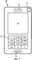
Фиг.1 показывает схематический вид служащего примером портативного устройства связи в форме сотового телефона с поддержкой WiFi.Figure 1 shows a schematic view of an exemplary portable communication device in the form of a WiFi enabled cell phone.
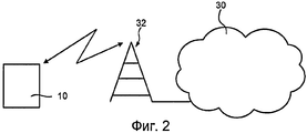
Фиг.2 показывает сотовый телефон на фиг.1, соединенный с сотовой сетью.FIG. 2 shows the cell phone of FIG. 1 connected to a cellular network.
Фиг.3 показывает схематическую блок-схему характерных частей сотового телефона на фиг.1-2.FIG. 3 shows a schematic block diagram of representative parts of the cell phone of FIGS. 1-2.
Фиг.4a показывает первую схематическую структуру, содержащую сотовый телефон на фиг.1-3 и три других WiFi-устройства.Fig. 4a shows a first schematic structure comprising the cell phone of Figs. 1-3 and three other WiFi devices.
Фиг.4b показывает вторую схематическую структуру, содержащую сотовый телефон на фиг.1-3 и три других WiFi-устройства.Fig. 4b shows a second schematic structure comprising the cell phone of Figs. 1-3 and three other WiFi devices.
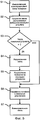
Фиг.5 показывает блок-схему выполнения способа согласно варианту осуществления настоящего изобретения.5 shows a flowchart of a method according to an embodiment of the present invention.
Фиг.6 показывает CD-ROM, на котором предоставлен программный код для выполнения способа согласно изобретению.6 shows a CD-ROM on which program code is provided for executing a method according to the invention.
Осуществление изобретенияThe implementation of the invention
Настоящее изобретение относится к портативным устройствам связи. Варианты осуществления изобретения относятся к беспроводным устройствам связи, а отдельные варианты осуществления относятся к устройствам связи, содержащим систему обработки изображений. В целом, изобретение может быть применено к любому подходящему портативному устройству связи.The present invention relates to portable communication devices. Embodiments of the invention relate to wireless communication devices, and individual embodiments relate to communication devices comprising an image processing system. In general, the invention can be applied to any suitable portable communication device.
Портативное устройство связи согласно предпочтительному варианту осуществления настоящего изобретения показано на фиг.1. Устройство предпочтительно является мобильным сотовым телефоном 10, приспособленным работать согласно 3G-технологии (например, W-CDMA или CDMA2000) или, возможно, по 2,5G-технологии (например, GPRS) или подобной технологии. Информация о 3G-технологии и 2,5G-технологии и т.д. может, например, быть найдена в спецификациях Проекта партнерства 3-го поколения (3GPP), см., например, веб-сайт по ссылке www.3gpp.org.A portable communication device according to a preferred embodiment of the present invention is shown in FIG. The device is preferably a
Сотовый телефон 10, показанный на фиг.1, снабжен клавиатурой 12, громкоговорителем 14 и микрофоном 16. Клавиатура 12 используется для ввода информации, такой как выбор функций и реагирование на подсказки. Клавиатура 12 может быть любого подходящего вида, в том числе, но не только, клавиатуры с нажимаемыми кнопками, также как и с сенсорными кнопками и/или комбинация различных подходящих конструкций кнопок. Громкоговоритель 14 используется для представления звуков пользователю, а микрофон 16 используется для восприятия голоса пользователя. Кроме того, сотовый телефон 10 включает в себя антенну, которая должна использоваться для связи с другими пользователями через сеть. Однако антенна встроена в телефон 10 и, следовательно, не показана на фиг.1. Кроме того, сотовый телефон 10 содержит дисплей 22 для отображения функций и подсказок пользователю телефона 10.The
Более того, сотовый телефон 10 содержит устройство 24 камеры, чтобы позволить цифровым образом записывать изображения посредством телефона 10. Предпочтительно, что устройство 24 камеры содержит объектив и/или систему линз и датчик изображений, такой как CCD (устройство с зарядовой связью), содержащий интегральную схему с матрицей связанных, или соединенных, конденсаторов, чувствительных к свету. Конечно, возможны другие датчики изображений, например APS (датчик активных пикселей), содержащий интегральную схему с матрицей пикселей, каждый из которых содержит фотодатчик, а также три или более транзисторов. Дисплей 22 может использоваться для представления изображений, записанных устройством 24 камеры.Moreover, the
Прежде чем мы продолжим, следует подчеркнуть, что сотовый телефон 10 на фиг.1 является только одним примером портативного устройства, в котором может быть реализовано изобретение. Изобретение, например, также может использоваться в PDA (персональный цифровой помощник), карманный компьютер, переносной компьютер или смартфон или любое другое подходящее портативное устройство, например, такое как цифровая камера.Before we continue, it should be emphasized that the
Фиг.2 показывает сотовый телефон 10, соединенный с сотовой сетью 30 через базовую станцию 32. Сеть 30 в типичном варианте является GSM или GPRS-сетью, или любой другой 2G-, 2,5G- или 2,75G-сетью. Конечно, также возможно, что сеть является 3G-сетью, такой как WCDMA-сеть. Однако сеть не обязательно должна быть сотовой сетью, а может быть неким типом сети, таким как Интернет, корпоративный интранет, LAN или беспроводная LAN.Figure 2 shows a
Фиг.3 показывает части внутренности сотового телефона 10, имеющие отношение к настоящему изобретению. Как объяснено ранее, предпочтительно, что сотовый телефон 10 содержит клавиатуру 12, динамик 14, микрофон 16, дисплей 22 и устройство 24 камеры. Также предпочтительно, что сотовый телефон 10 снабжен памятью 18 для хранения файлов данных, в частности файлов изображений, созданных устройством 24 камеры. Память 18 может быть любым подходящим типом памяти, который в типичном варианте используется в портативных устройствах.3 shows parts of the interior of a
Кроме того, сотовый телефон 10 содержит антенну 34, соединенную с радиосхемой 36, чтобы предоставить возможность радиосвязи с сетью 30 на фиг.2. Радиосхема 36, в свою очередь, соединена с блоком 19 обработки событий для обработки таких событий, как исходящая и входящая связь к и от внешних блоков через сеть 30, например вызовы и сообщения, например SMS (служба коротких сообщений) и MMS (служба мультимедийных сообщений).In addition, the
Особым интересом в связи с вариантом осуществления, который теперь описывается, является блок 50 малого радиуса действия, показанный на фиг.3. Блоком 50 малого радиуса действия предпочтительно является так называемый WiFi-приемопередатчик. Как объяснено выше, WiFi является торговой маркой, которая была изначально лицензирована альянсом WiFi, чтобы описать лежащую в основе технологию WLAN на базе спецификаций IEEE 802.11 или т.п. Человек с WiFi-устройством, таким как сотовый телефон или PDA или т.п., может, например, соединяться с Интернетом, когда находится поблизости от точки доступа. Пространство, покрываемое одной или несколькими точками доступа, называется "горячей" точкой. WiFi также предоставляет возможность связи в одноранговом режиме, который разрешает устройствам соединяться непосредственно друг с другом. Этот режим связности является полезным, например, в бытовой электронной аппаратуре и игровых приложениях.Of particular interest in connection with the embodiment that is now described is the short range unit 50 shown in FIG. 3. The short-range unit 50 is preferably a so-called WiFi transceiver. As explained above, WiFi is a trademark that was originally licensed by the WiFi alliance to describe the underlying WLAN technology based on IEEE 802.11 specifications or the like. A person with a WiFi device, such as a cell phone or PDA or the like, can, for example, connect to the Internet when it is in the vicinity of an access point. The space covered by one or more access points is called a hot spot. WiFi also provides peer-to-peer connectivity, which allows devices to connect directly to each other. This connectivity mode is useful, for example, in consumer electronics and gaming applications.
Как схематически иллюстрировано на фиг.3, блок 50 малого радиуса действия предпочтительно соединен с первой, по существу, всенаправленной антенной 52 для, по существу, всенаправленной связи с другими WiFi-устройствами или т.п. поблизости от сотового телефона 10. Кроме того, как подобно схематически иллюстрировано на фиг.3, блок 50 малого радиуса действия предпочтительно соединен со второй, по существу, направленной антенной 54 для, по существу, направленной связи с другими WiFi- устройствами или т.п. поблизости от сотового телефона 10.As schematically illustrated in FIG. 3, the short range unit 50 is preferably connected to a first substantially omnidirectional antenna 52 for substantially omnidirectional communication with other WiFi devices or the like. in the vicinity of the
В частности, блок 50 малого радиуса действия выполнен с возможностью оперативного переключения между, по существу, всенаправленной антенной 52 и, по существу, направленной антенной 54. Для этого блок 50 малого радиуса действия может содержать переключатель (не показан) или аналогичное средство выбора одной из двух антенн 52, 54 при связи с другими WiFi-устройствами. Переключатель может, например, быть осуществлен посредством диода и/или транзисторной схемы или т.п., как хорошо известно специалистам в данной области техники.In particular, the short-range unit 50 is configured to quickly switch between a substantially omnidirectional antenna 52 and a substantially directional antenna 54. For this, the short-range unit 50 may include a switch (not shown) or similar means for selecting one of two antennas 52, 54 when communicating with other WiFi devices. The switch may, for example, be implemented by a diode and / or transistor circuit or the like, as is well known to those skilled in the art.
Следует добавить, что направленные и всенаправленные свойства антенной схемы, содержащей направленную антенну 54 и всенаправленную антенну 52, могут быть достигнуты посредством ряда подходящих схем с направленной антенной. Например, антенная схема может альтернативно содержать группу антенн или т.п., например, электрически управляемую фазированную антенную решетку, выполненную с возможностью создавать переменный лепесток диаграммы направленности антенны, т.е., широкий или, возможно, всенаправленный лепесток и узкий направленный лепесток. Для этого блок 50 малого радиуса действия может быть снабжен схемой управления лепестком диаграммы направленности антенны для управления формой лепестка групповой антенны или т.п. В типичном варианте такие схемы управления лепестком регулируют сдвиг φ относительной фазы между последовательными антенными элементами в групповой антенне, как хорошо известно специалистам в данной области техники.It should be added that the directional and omnidirectional properties of an antenna circuit comprising a directional antenna 54 and omnidirectional antenna 52 can be achieved by a number of suitable directional antenna circuits. For example, the antenna circuit may alternatively comprise a group of antennas or the like, for example, an electrically controlled phased array antenna configured to create an alternating lobe of the antenna pattern, i.e., a wide or possibly omnidirectional lobe and a narrow directional lobe. For this, the short-range unit 50 may be provided with an antenna pattern control circuit for controlling the shape of a group antenna band or the like. Typically, such lobe control circuits control the shift of the relative phase φ between successive antenna elements in a group antenna, as is well known to those skilled in the art.
Как может быть видно на фиг.3, сотовый телефон 10 также снабжен блоком 20 управления для управления и наблюдения за работой телефона 10. Блок 20 управления может быть осуществлен посредством аппаратных средств и/или программного обеспечения, и он может содержать один или несколько аппаратных блоков и/или программных модулей, например один или несколько процессоров, обеспеченных доступом или имеющих доступ к соответствующему программному обеспечению и аппаратным средствам, необходимым для функций, требуемых телефоном 10, как хорошо известно специалистам в области техники.As can be seen in FIG. 3, the
Предпочтительно, чтобы блок 20 управления был соединен с клавиатурой 12, динамиком 14, микрофоном 16, памятью 18, блоком 19 обработки событий, дисплеем 22, камерой 24, радиоблоком 36 и блоком 50 малого радиуса действия. Это позволяет блоку 20 управления управлять и связываться с этими блоками с тем, чтобы, например, обмениваться информацией и инструкциями с блоками.Preferably, the control unit 20 is connected to a
Особый интерес в связи с настоящим изобретением представляет элемент 40 управления малого радиуса действия, содержащийся в блоке 20 управления. Являясь частью блока 20 управления, подразумевается, что элемент 40 управления малого радиуса действия может быть осуществлен посредством аппаратных средств и/или программного обеспечения, и он может содержать один или несколько аппаратных блоков и/или программных модулей, например один или несколько процессоров, обеспеченных доступом или имеющих доступ к программному обеспечению и аппаратным средствам, подходящим для требуемых функций. Элемент 40 управления малого радиуса действия предпочтительно выполнен с возможностью оперативно обрабатывать сигналы, которые передаются и/или принимаются блоком 50 малого радиуса действия, например, выполнен с возможностью обрабатывать сигналы вместе с WLAN-соединением, выполняемым посредством блока 50 малого радиуса действия. Передача посредством WLAN-соединения и управление им хорошо известны специалистам в области техники, и функция является общим признаком в широком диапазоне хорошо известных портативных устройств, см., например, 3G-смартфон P990i фирмы Sony-Ericsson. Кроме того, элемент 40 управления малого радиуса действия выполнен с возможностью оперативного управления лепестком диаграммы направленности антенны, созданным антенной схемой, соединенной с блоком 50 малого радиуса действия. В случае, если антенная схема содержит первую всенаправленную антенну 52 и вторую направленную антенну 54, лепесток диаграммы направленности антенны может управляться, например, посредством переключения между двумя антеннами. Для этого предпочтительно, чтобы переключатель, размещенный в блоке 50 малого радиуса действия, оперативно управлялся элементом 40 управления малого радиуса действия, например, посредством инструкций, отправленных блоку 50 малого радиуса действия. В случае, если антенная схема является групповой антенной (например, фазированной антенной решеткой) или похожей антенной схемой, предоставляющей переменный лепесток диаграммы направленности антенны, предпочтительно, чтобы устройство управления лепестком было размещено в блоке 50 малого радиуса действия, чтобы оперативно управляться элементом 40 управления малого радиуса действия, например, посредством инструкций, отправленных блоку 50 малого радиуса действия. Такие инструкции могут, например, содержать сдвиг φ относительной фазы, который должен использоваться между последовательными антенными элементами в групповой антенне.Of particular interest in connection with the present invention is the short-range control element 40 contained in the control unit 20. As part of the control unit 20, it is understood that the short-range control element 40 can be implemented by hardware and / or software, and it can contain one or more hardware units and / or software modules, for example, one or more processors provided with access or having access to software and hardware suitable for the required functions. The short-range control element 40 is preferably configured to operatively process signals that are transmitted and / or received by the short-range unit 50, for example, configured to process signals along with a WLAN connection performed by the short-range unit 50. WLAN transmission and control are well known to those skilled in the art, and the feature is a common feature in a wide range of well-known portable devices, see, for example, Sony-Ericsson's P990i 3G smartphone. In addition, the short-range control element 40 is arranged to operatively control the antenna beam created by the antenna circuit connected to the short-range unit 50. In the event that the antenna circuit includes a first omnidirectional antenna 52 and a second directional antenna 54, the antenna beam can be controlled, for example, by switching between two antennas. For this, it is preferable that the switch located in the short-range block 50 is operatively controlled by the short-range control element 40, for example, by instructions sent to the short-range block 50. If the antenna circuit is a group antenna (for example, a phased array) or a similar antenna circuit providing a variable antenna pattern, it is preferable that the petal control device be placed in a short range unit 50 so that it can be quickly controlled by a small control element 40 range, for example, through instructions sent to the short range unit 50. Such instructions may, for example, comprise a relative phase shift φ that should be used between consecutive antenna elements in a group antenna.
Прежде чем мы продолжим, следует подчеркнуть, что в дополнение к частям и блокам сотового телефона, показанного на фиг.3, могут быть дополнительные части и блоки или т.п., присутствующие в сотовом телефоне 10. Части и блоки, показанные на фиг.3, также могут быть соединены с большим числом частей и блоков, чем иллюстрировано.Before we continue, it should be emphasized that in addition to the parts and blocks of the cell phone shown in FIG. 3, there may be additional parts and blocks or the like present in the
Теперь обратим внимание на фиг.4a, который показывает первую служащую примером структуру из четырех WiFi-устройств, т.е. сотовый телефон 10, который описан выше, и три одноранговых узла 10a, 10b и 10c. WiFi-устройства 10a-10c на фиг.4a могут быть, например, WiFi-компьютером, CD-проигрывателем, DVD-проигрывателем, телевизором, камерой, телефоном, PDA или любым другим WiFi-мультимедийным устройством или т.п., например массовым запоминающим устройством. Устройства 10a-10c в типичном варианте размещены в одной и той же комнате или в одном и том же здании или в похожем узком пространстве так, что передача маякового радиосигнала или т.п., по меньшей мере, от двух и типично всех устройств 10a-10c может быть обнаружена одновременно сотовым телефоном 10, по меньшей мере, в одном местоположении. Технология обнаружения одного или нескольких WiFi-устройств и т.п. хорошо известна специалистам в области техники и часто используется в коммерчески доступных продуктах, таких как сотовые телефоны и переносные компьютеры, см., например, 3G-смартфон P990i фирмы Sony-Ericsson. Дальности передачи WiFi-устройств 10a-10c были схематически иллюстрированы на фиг.4a посредством заштрихованных кругов. Как может быть видно, дальности передачи иллюстрированы скорее небольшими кругами, и следует понимать, что диапазоны могут быть более протяженными. В действительности, диапазоны передачи могут быть настолько большими по сравнению с расстоянием между устройствами 10a-10c, так что пространство, покрываемое устройствами 10a-10c, может рассматриваться как, по существу, идентичное. Когда WiFi-сотовый телефон 10, снабженный всенаправленной антенной 52, входит в такое пространство, он будет иметь возможность потенциально соединяться с каждым устройством 10a-10c, от которых он принимает передачу маякового радиосигнала или т.п., т.е. во многих случаях он будет способен соединяться со всеми устройствами 10a-10c.Now, pay attention to FIG. 4a, which shows the first example structure of four WiFi devices, i.e. a
Чтобы предоставить возможность быстрого, простого и интуитивного выбора устройства 10a-10c, с которым сотовый телефон 10 должен связаться, предпочтительно, чтобы всенаправленная антенна 52 была выключена, в то время как направленная антенна 54 включена, чтобы предпочтительно сформировать узкий лепесток 54' диаграммы направленности антенны. Лепесток 54' диаграммы направленности антенны может быть, например, в интервале, по существу, 20°-40°, а более предпочтительно в интервале, по существу, 10-30° и наиболее предпочтительно в интервале, по существу, 15°-25°. Узкий лепесток 54' диаграммы направленности антенны был схематически указан на фиг.4a затемненным сектором круга. Переключение с всенаправленной антенны 52 на направленную антенну 54, например, может быть выполнено нажатием пользователем кнопки на клавиатуре 22, которое обнаруживается блоком 20 управления, и элемент 40 управления малого радиуса действия отправляет инструкции блоку 50 малого радиуса действия, чтобы переключиться с всенаправленной антенны 52 на направленную антенну 54. Альтернативно, всенаправленная антенна 52 может выключаться, а направленная антенна 54 включаться, как только сотовый телефон 10 обнаруживает более чем одно WiFi-устройство в диапазоне действия всенаправленной антенны 52.In order to enable the quick, easy, and intuitive selection of the
Кроме того, когда передача переключается с всенаправленной антенны 52 на направленную антенну 54, предпочтительно, чтобы мощность передачи была уменьшена элементом 40 управления малого радиуса действия и/или блоком 50 малого радиуса действия. Это является полезным, так как уменьшает дальность передачи и, таким образом, уменьшается риск того, что более чем одно расположенное поблизости WiFi-устройство принимает направленную передачу сигнала с тем, чтобы иметь возможность связаться с сотовым телефоном 10, т.е. функция выбора будет улучшена в том, что шансы выбора только одного расположенного поблизости WiFi-устройства увеличиваются.Furthermore, when the transmission is shifted from the omnidirectional antenna 52 to the directional antenna 54, it is preferable that the transmission power be reduced by the short-range control element 40 and / or the short-range unit 50. This is useful because it reduces the transmission range and, thus, reduces the risk that more than one nearby WiFi device receives directional signal transmission in order to be able to communicate with the
После того как направленная антенна 54 активирована, сотовый телефон 10 будет иметь возможность обнаруживать только те другие WiFi-устройства, которые находятся в пределах лепестка диаграммы направленности направленной антенны 54. Другими словами, сотовый телефон не обнаружит WiFi-устройство, которое расположено вне лепестка направленной антенны 54. Это так, даже если WiFi-устройство расположено очень близко к сотовому телефону 10, по меньшей мере, если мы предположим идеальный лепесток диаграммы направленности антенны.After the directional antenna 54 is activated, the
Однако в некоторых вариантах осуществления изобретения может быть трудно реализовать направленную антенну 54 с лепестком 54' диаграммы направленности антенны в предпочтительных угловых интервалах, которые обсуждались выше. Кроме того, направленная антенна 54 может иметь боковые лепестки, вызывающие нежелательную чувствительность вне главного лепестка 54' антенны. Следовательно, даже если направленная антенна 54 активирована, и центр лепестка 54' направленной антенны направлен на определенное WiFi-устройство, сотовый телефон 10 может, тем не менее, обнаружить несколько WiFi-устройств. Однако уровень сигнала от определенного WiFi-устройства рядом или в центре лепестка 54' направленной антенны будет, по существу, неизменным или даже более сильным по сравнению с уровнем сигнала от того же устройства, принятого всенаправленной антенной 52. Как противоположность, другие WiFi-устройства, которые не находятся рядом или в центре лепестка 54' направленной антенны, будут иметь ослабление в уровне сигнала. Следует добавить, что в случае, когда направленная антенна 54 имеет низкий коэффициент усиления, уровень сигнала от определенного WiFi-устройства рядом или в центре лепестка 54' направленной антенны 54 может быть ниже, чем уровень сигнала, принятого от того же устройства всенаправленной антенной 52. Однако по сравнению с уровнями сигналов, принятых всенаправленной антенной 52, степень уменьшения в уровне сигнала для WiFi-устройства рядом или в центре лепестка 54' антенны будет меньше, чем степень уменьшения в уровне сигнала для других WiFi-устройств, которые не находятся рядом с центром лепестка 54' направленной антенны.However, in some embodiments of the invention, it may be difficult to realize a directional antenna 54 with a beam pattern 54 'of the antenna pattern in the preferred angular ranges discussed above. In addition, the directional antenna 54 may have side lobes causing undesirable sensitivity outside the main lobe 54 'of the antenna. Therefore, even if the directional antenna 54 is activated and the center of the lobe of the directional antenna 54 'is directed to a specific WiFi device, the
Следовательно, со ссылкой на фиг.4a, WiFi-устройство 10a может быть более точно отобрано в некоторых вариантах осуществления изобретения, если всенаправленная антенна 52 активируется для первого измерения уровней сигналов от расположенных поблизости WiFi-устройств 10a-10c, при этом направленная антенна 54 активируется для второго измерения уровня сигнала, по меньшей мере, от одного расположенного поблизости WiFi-устройства, когда направленная антенна 54 направлена на определенное расположенное поблизости WiFi-устройство 10a. Сотовый телефон 10 затем может быть соединен с расположенным поблизости WiFi-устройством 10a, которое имеет, по существу, одинаковый уровень сигнала при первом и втором измерениях или имеет больший уровень сигнала при втором измерении. Альтернативно, в случае направленной антенны с низким коэффициентом усиления сотовый телефон 10 может быть соединен с расположенным поблизости WiFi-устройством 10a, которое показывает самую низкую степень уменьшения в уровне сигнала с первого по второе измерение.Therefore, with reference to FIG. 4a, the
Следует добавить, что уровень принятого сигнала для WiFi-устройства в типичном варианте содержится в значении индикатора уровня принятого сигнала (RSSI) для передающего устройства. Поэтому предпочтительно, чтобы сотовый телефон 10 был выполнен с возможностью измерять вышеуказанные уровни сигналов посредством наблюдения RSSI-значения для расположенных поблизости WiFi-устройств 10a-10c.It should be added that the received signal strength for a WiFi device is typically contained in the value of the received signal strength indicator (RSSI) for the transmitting device. Therefore, it is preferable that the
Как описано выше, активация направленной антенны 54 позволяет пользователю сотового телефона 10 выбирать WiFi-устройство, с которым сотовый телефон 10 будет связываться, посредством простого направления сотового телефона 10 и лепестка 54' антенны на выбранное WiFi-устройство. Это иллюстрировано на фиг.4a схематическим лепестком 54' диаграммы направленности антенны, исходящим от направленной антенны 54 сотового телефона 10, направляемого на WiFi-устройство 10a. Как видно на фиг.4a, устройством 10a теперь является только WiFi-устройство в диапазоне сотового телефона 10, и сотовый телефон 10 может быть недвусмысленно и безопасно соединен с WiFi-устройством 10a.As described above, activating the directional antenna 54 allows the user of the
Обнаружение одного WiFi-устройства может, например, быть указано на дисплее 22 и/или посредством особого звука из громкоговорителя 14 сотового телефона 10. Соединение с одним WiFi-устройством может, например, быть выполнено посредством нажатия пользователем кнопки на клавиатуре 22, которое обнаруживается блоком 20 управления и элементом 40 управления малого радиуса действия, выполненным с возможностью функционально связывать сотовый телефон 10 с одним WiFi-устройством посредством блока 50 малого радиуса действия. Альтернативно, соединение с одним WiFi-устройством может быть выполнено блоком 20 управления и т.д. настолько быстро, насколько сотовый телефон 10 обнаруживает одно WiFi-устройство в диапазоне действия направленной антенны 54.The detection of one WiFi device may, for example, be indicated on the
После того как соединение с выбранным WiFi-устройством было установлено, предпочтительно, чтобы направленная антенна 54 была выключена, в то время как всенаправленная антенна 52 включена для простоты поддержания соединения, так как сотовый телефон 10 и, возможно, также выбранное WiFi-устройство могут перемещаться.After the connection with the selected WiFi device has been established, it is preferable that the directional antenna 54 is turned off, while the omnidirectional antenna 52 is turned on for ease of connection, since the
Альтернативный вариант осуществления настоящего изобретения схематически иллюстрирован на фиг.4b, который показывает вторую приведенную в качестве примера структуру из четырех WiFi-устройств, т.е. сотовый телефон 10, который описан выше, и три одноранговых узла 10a, 10b и 10c. Вариант осуществления характеризуется тем, что направленная антенна 54 сотового телефона 10 была заменена направленным датчиком света. Здесь предпочтительно, чтобы устройство 24 камеры использовалось в качестве направленного датчика света. Это решение особенно полезно, так как оно использует существующие аппаратные средства (камеру), т.е. решение не требует дополнительных аппаратных средств. Угол, под которым камера 24 записывает свет, предпочтительно регулируется так, чтобы быть одинаковым или подобным углу лепестка 54' диаграммы направленности антенны, описанному выше. Это, например, может быть достигнуто посредством устройства автофокусировки для увеличения или уменьшения угла записи, как хорошо известно специалистам в данной области техники. В этом способе лепесток 24' восприятия света может быть создан камерой 24, как схематически иллюстрировано на фиг.4b. Активация камеры 24 в качестве датчика света, например, может быть выполнена посредством нажатия пользователем кнопки на клавиатуре 22. Это обнаруживается блоком 20 управления, который, в свою очередь, активирует камеру 24. Альтернативно, камера 24 может быть активирована в качестве датчика света, как только сотовый телефон 10 обнаруживает более чем одно WiFi-устройство в диапазоне действия всенаправленной антенны 52.An alternative embodiment of the present invention is schematically illustrated in FIG. 4b, which shows a second exemplary structure of four WiFi devices, i.e. a
Из вышесказанного наблюдательный читатель поймет, что рассматриваемый сейчас вариант осуществления, предполагает, что WiFi-устройство, которое должно быть выбрано, снабжено устройством излучения света, подходящим, чтобы излучать свет, который может быть обнаружен камерой 24, т.е. средством восприятия света камеры 24. Для этого лепесток 10a' света, происходящий от WiFi-устройства 10a, был схематически указан на фиг.4b затемненным сектором круга. Угол рассеивания лепестка 10a' света может быть таким же или похожим на угол лепестка 54' направленной антенны, обсужденного выше. Однако очевидно, что возможен больший угол. Свет может быть модулирован и/или закодирован, и из этого следует, что сотовый телефон 24 в таких случаях должен иметь возможность демодулировать/декодировать модулированный/закодированный свет. Во многих случаях предпочтительно, чтобы свет от WiFi-устройства 10a содержал полезную информацию о соединении, чтобы облегчить соединение других WiFi-устройств, таких как сотовый телефон 10. Информация о соединении может, например, содержать название сети (например, идентификатор беспроводной сети, SSID) или т.п., к которой принадлежит WiFi-устройство, и, возможно, идентичность или т.п. рассматриваемого WiFi-устройства. Свет, излучаемый WiFi-устройством 10a, может также содержать такую полезную информацию о соединении, как диапазон частот, в котором работает устройство, канал в этом диапазоне, является ли соединение открытым или закрытым, тарифы, которые должны использоваться, и т.д. Хотя не является необходимым в качестве условия для изобретения, предпочтительно, чтобы свет, излучаемый WiFi-устройством, был невидимым для человеческого глаза (например, инфракрасный свет или т.п.), чтобы избежать беспокойства пользователя и других людей. Здесь следует отметить, что полупроводниковые датчики света, такие как CCD, используемые в цифровых камерах, в типичном варианте чувствительны к инфракрасному свету.From the foregoing, the observing reader will understand that the embodiment currently being considered assumes that the WiFi device to be selected is provided with a light emitting device suitable to emit light that can be detected by the
После того как воспринимающая свет камера 24 сотового телефона 10 была активирована, она позволяет пользователю сотового телефона 10 выбрать WiFi-устройство, которое должно быть соединено с сотовым телефоном 10, посредством простого направления сотового телефона 10 и камеры 24 на рассматриваемое WiFi-устройство, например WiFi-устройство 10a, как иллюстрировано на фиг.4b. Когда сотовый телефон 10 принимает свет от WiFi-устройства 10a, предпочтительно, чтобы сотовый телефон 10 получал информацию о соединении, содержащуюся в свете, например название сети или т.п., к которой принадлежит WiFi-устройство 10a, и, возможно, идентичность или т.п. WiFi-устройства 10a. Информация о соединении затем используется сотовым телефоном 10 для установления соединения с WiFi-устройством, указанным посредством сотового телефона 10 и камеры 24.Once the light-sensing
В качестве дополнительного признака, соединение с WiFi-устройством выполняется, только когда сотовый телефон 10 обнаруживает свет от одного WiFi-устройства, т.е. не делается попытки установить соединение, когда сотовый телефон 10 обнаруживает световое излучение от двух WiFi-устройств или более. Свет от различных WiFi-устройств может, например, содержать, различные несущие частоты с тем, чтобы разрешить сотовому телефону 10 обнаруживать свет от двух или более WiFi-устройств посредством анализа частотного содержимого принятого света.As an additional feature, the connection with the WiFi device is only performed when the
После того как соединение с выбранным WiFi-устройством было установлено, предпочтительно, чтобы воспринимающая свет камера 24 была выключена, в то время как всенаправленная антенна 52 включена для легкости поддержки соединения, так как сотовый телефон 10 и, возможно, также выбранное WiFi-устройство могут перемещаться.After the connection with the selected WiFi device has been established, it is preferable that the light-sensing
Предпочтительно, чтобы альтернативный вариант осуществления на основе света, описанный выше, поддерживал всенаправленную антенну 52 активной во время процедуры соединения, т.е. предпочтительно не переключался или т.п. между направленной антенной и всенаправленной антенной, как происходит в ранее описанном варианте осуществления. Однако описываемые сейчас варианты осуществления могут быть объединены для улучшенной надежности (и безопасности) в процессе соединения.It is preferred that the light-based alternative embodiment described above keep the omnidirectional antenna 52 active during the connection procedure, i.e. preferably not switched or the like between a directional antenna and an omnidirectional antenna, as occurs in the previously described embodiment. However, the embodiments described now can be combined for improved reliability (and security) during the connection process.
Другой альтернативный вариант осуществления настоящего изобретения использует содержимое изображения, записанного устройством 24 камеры сотового телефона 10. Содержимое записанного изображения предпочтительно анализируется с тем, чтобы идентифицировать возможные расположенные поблизости WiFi-устройства, захваченные в изображении. Это может быть выполнено с помощью изменения точности посредством, по существу, любой подходящей хорошо известной технологии распознавания изображения, которая, например, может сравнивать текущее записанное изображение или его представление с предварительно сохраненными справочными изображениями различных WiFi-устройств 10a-10c или их представлениями. Хорошо известными примерами являются байесовский классификатор максимального апостериорного различия (Байесовский MAP) или т.п., или байесовский классификатор, использующий метод максимального правдоподобия (Байесовский MP) или т.п. Справочные изображения или их представления могут быть записаны и/или получены и сохранены в сотовом телефоне 10 заранее. В частности, устройство 24 камеры сотового телефона 10 может использоваться, чтобы записать такие справочные изображения WiFi-устройств 10a-10c, которые предназначены для соединения с сотовым телефоном 10. Изображения и/или их представления затем могут быть сохранены в сотовом телефоне 10 вместе с информацией о WiFi-устройстве, захваченном рассматриваемым изображением, например, сохранены вместе с информацией о соединении, такой как название сети (например, идентификатор беспроводной сети, SSID) или т.п., идентичность или т.п. рассматриваемого WiFi-устройства, частотный диапазон, в котором WiFi-устройство предполагает работать, канал в этом диапазоне, является ли соединение открытым или закрытым, тарифы, которые должны использоваться, и т.д. Информация о соединении и т.п. может, например, быть введена пользователем с помощью кнопок на клавиатуре 12 сотового телефона 10. В случае, когда WiFi-устройство фактически идентифицировано в текущем записанном изображении - например, WiFi-устройство 10a, как показано на фиг.4b - возможно соединить сотовый телефон 10 с идентифицированным устройством 10a с помощью информации об идентифицированном устройстве 10a, которая была предварительно сохранена в сотовом телефоне 10 вместе с изображением идентифицированного устройства 10a.Another alternative embodiment of the present invention uses the contents of the image recorded by the
Прежде чем мы продолжим, следует добавить, что WiFi-устройства 10a-10c, с которыми должен связываться сотовый телефон 10, предпочтительно снабжены видимыми информационными ярлыками или похожими метками, содержащими полезную информацию о соединении, чтобы облегчить соединение WiFi-устройств 10a-10c с сотовым телефоном 10. Метки могут, например, содержать двухмерный штрих-код или некоторый другой шаблон, содержащий представление, например, названия сети (например, идентификатор беспроводной сети, SSID) или т.п., к которой принадлежит рассматриваемое WiFi-устройство, и/или идентичность или т.п. рассматриваемого WiFi-устройства и т.д. В этих случаях изображение, записанное устройством 24 камеры, может содержать такие метки. Следовательно, предпочтительно, чтобы элемент 40 управления малого радиуса действия сотового телефона 10 был выполнен с возможностью оперативно извлекать любую полезную информацию о соединении из возможных меток в записанном изображении, чтобы облегчить соединение других WiFi-устройств, таких как сотовый телефон 10. Например, если шаблон является двухмерным штрихкодом, это может быть сделано посредством простого извлечения информации, содержащейся в штрихкоде, хорошо известным образом (независимо от контекста, например, обычные кассы в обычных магазинах).Before we continue, it should be added that the
Теперь внимание направлено на функционирование приводимого в качестве примера варианта осуществления настоящего изобретения, который будет описан со ссылкой на фиг.1-3 вместе с фиг.4a-4c, иллюстрирующими две служащих примером структуры WiFi-устройств, и фиг.5, показывающую блок-схему предпочтительного способа согласно варианту осуществления изобретения.Attention is now directed to the operation of an exemplary embodiment of the present invention, which will be described with reference to FIGS. 1-3, with FIGS. 4a-4c illustrating two serving example structures of WiFi devices, and FIG. 5 showing a block a diagram of a preferred method according to an embodiment of the invention.
Как объяснено ранее, служащее примером портативное устройство в форме сотового телефона 10 согласно варианту осуществления изобретения снабжено блоком 50 малого радиуса действия, выполненным с возможностью оперативно устанавливать беспроводную WiFi-связь с расположенным поблизости WiFi-устройством. Кроме того, сотовый телефон снабжен, по существу, всенаправленной антенной 52, соединенной с упомянутым блоком 50 малого радиуса действия, чтобы разрешить, по существу, всенаправленную связь с упомянутым расположенным поблизости WiFi-устройством. Сотовый телефон 10 содержит, по меньшей мере, одно устройство 54, 24 направленной связи, выполненное с возможностью оперативного обмена информацией о соединении с упомянутым расположенным поблизости WiFi-устройством, когда устройство 54, 24 направленной связи направлено на упомянутое расположенное поблизости WiFi-устройство.As explained previously, an exemplary portable device in the form of a
Этапы в приводимом в пример способе установления беспроводной связи между сотовым телефоном 10 и расположенным поблизости WiFi-устройством теперь будут описаны со ссылкой на приводимую в пример блок-схему на фиг.5. Способ предпочтительно выполняется посредством элемента 40 управления малого радиуса действия и блока 50 малого радиуса действия.The steps in the exemplary method for establishing wireless communication between the
На первом этапе S1 служащего примером способа согласно варианту осуществления настоящего изобретения функция соединения инициализируется элементом 40 управления малого радиуса действия, управляющим блоком 50 малого радиуса действия. Инициализация включает в себя такие действия, как активация сотового телефона 10, чтобы искать расположенные поблизости WiFi-устройства 10a-10c посредством всенаправленной антенны 52. Поиск предпочтительно выполняется, как хорошо известно специалистам в данной области техники, посредством прослушивания передач маякового радиосигнала или т.п. от возможных WiFi-устройств 10a-10c поблизости от сотового телефона 10.In a first step S1 of an example method according to an embodiment of the present invention, the connection function is initialized by the short-range control element 40, the short-range control unit 50. Initialization includes actions such as activating a
На втором этапе S2 служащего примером способа подготавливается список или т.п., содержащий расположенные поблизости WiFi-устройства 10a-10c, от которых сотовый телефон 10 принял передачу маякового радиосигнала или т.п. Список может, например, содержать названия сетей или т.п., к которым принадлежит определенное WiFi-устройство 10a-10c, и, возможно, идентичность или т.п. рассматриваемого WiFi-устройства. Название сети и, возможно, другие такие факты в типичном варианте содержатся в передаче маякового радиосигнала, принятой от WiFi-устройства. Подготовленный список может быть представлен на дисплее 22 портативного устройства связи (например, сотовый телефон 10), как хорошо известно. Однако представление не требуется для настоящего изобретения.In a second step S2 of an example method, a list or the like is prepared containing
На третьем этапе S3 изучается, содержит ли вышеупомянутый список более чем одно WiFi-устройство, т.е. принял ли сотовый телефон 10 передачу маякового радиосигнала или т.п. от более чем одного WiFi-устройства. Если список содержит одно WiFi-устройство, предпочтительно, чтобы сотовый телефон 10 установил соединение с этим устройством, как указано на фиг.5 линией, протягивающейся от блока S3 в форме параллелограмма к блоку S6 в форме квадрата.In the third step S3, it is examined whether the aforementioned list contains more than one WiFi device, i.e. whether
На четвертом этапе S4 предпочтительно, чтобы пользователь сотового телефона 10 активировал канал направленной связи. Как описано выше, это может включать в себя активацию направленной антенны 54 или направленного датчика 24 света. Однако изобретение не ограничено связью посредством направленного электромагнитного излучения, в целом, и направленного света, в частности. Другое средство, такое как, например, направленный ультразвук или т.п., может быть использовано в некоторых вариантах осуществления. Активация направленной функции может, например, быть выполнена посредством нажатия пользователем кнопки на клавиатуре 22, что обнаруживается блоком 20 управления, как описано выше. Активация направленной функции может также быть выполнена, когда активируется определенная прикладная программа, например, когда пользователь выбирает фото или некоторый другой мультимедийный элемент данных или развлекательный элемент данных, который должен быть передан другому расположенному поблизости WiFi-устройству. Выбор, например, может быть выполнен посредством нажатия пользователем кнопки на клавиатуре 22. Альтернативно, активация направленной функции может быть выполнена, как только сотовый телефон 10 обнаруживает множество WiFi-устройств в диапазоне действия направленной антенны 54.In the fourth step S4, it is preferable that the user of the
На пятом этапе S5 предпочтительно, чтобы пользователь сотового телефона 10 выбрал WiFi-устройство, к которому должно быть осуществлено подключение, направляя сотовый телефон 10 на упомянутое WiFi-устройство, как описано выше со ссылкой на фиг.4a-4b.In the fifth step S5, it is preferable that the user of the
На шестом этапе S6 предпочтительно, чтобы сотовый телефон 10 соединялся с выбранным WiFi-устройством 10a. Для этого предпочтительно, чтобы выбранное WiFi-устройство передавало информацию о соединении с тем, чтобы облегчить соединение выбранного WiFi-устройства с сотовым телефоном 10. Как ранее описано, информация о соединении может, например, содержать название сети или т.п., к которой принадлежит WiFi-устройство, и, возможно, идентичность или т.п. рассматриваемого WiFi-устройства. Переданная информация о соединении позволяет сотовому телефону 10 соединяться с выбранным WiFi-устройством, например, посредством соединения с сетью и/или устройством, содержащимися в информации о соединении, или посредством соединения только с WiFi-устройством, которое отвечает на попытки соединения, выполняемые сотовым телефоном 10. Следует подчеркнуть, что информация о соединении может быть просто светом, излученным источником света, размещенным в WiFi-устройстве, как в одном варианте осуществления, описанном выше со ссылкой на фиг.4b.In the sixth step S6, it is preferable that the
На седьмом этапе S7 предпочтительно, чтобы сотовый телефон 10 продолжал связь с выбранным WiFi-устройством посредством всенаправленной антенны, после того как соединение было установлено с выбранным WiFi-устройством посредством направленного канала связи.In the seventh step S7, it is preferable that the
Следует подчеркнуть, что способ, описанный выше, является просто примером настоящего изобретения. Другие варианты осуществления способа могут содержать больше этапов или меньше этапов, и этапы могут выполняться в другом порядке, чем приведено выше.It should be emphasized that the method described above is just an example of the present invention. Other embodiments of the method may comprise more steps or fewer steps, and the steps may be performed in a different order than above.
Вообще, как объяснено ранее, предпочтительно, чтобы элемент 40 управления малого радиуса действия, выполненный с возможностью выполнения служащего примером способа, описанного выше, был представлен в форме одного или более процессоров с соответствующей памятью, содержащей соответствующее программное обеспечение в форме программного кода. Однако программный код может также быть предоставлен на носителе данных, таком как диск 46 CD-ROM, как изображено на фиг.6, или вставляемая карта памяти, который может осуществлять изобретение, когда загружен в компьютер или в телефон, имеющий подходящие возможности обработки. Программный код может также быть загружен удаленно с сервера либо вне, либо внутри сотовой сети или быть загружен через компьютер типа PC, к которому телефон временно подключен.In general, as explained previously, it is preferable that the short-range control element 40, configured to execute an example of the method described above, is presented in the form of one or more processors with corresponding memory containing appropriate software in the form of program code. However, program code may also be provided on a storage medium, such as a CD-
Настоящее изобретение было описано со ссылкой на служащие примером варианты осуществления. Однако изобретение не ограничено вариантами осуществления, описанными в данном документе. Наоборот, полная степень изобретения определяется только рамками прилагаемой формулы изобретения.The present invention has been described with reference to exemplary embodiments. However, the invention is not limited to the embodiments described herein. On the contrary, the full extent of the invention is determined only by the scope of the attached claims.
Claims (10)
при этом способ содержит этапы, на которых:
- активируют устройство (24) направленной связи,
- направляют устройство (24) направленной связи на расположенное поблизости беспроводное устройство (10а),
- соединяют портативное устройство (10) с выбранным устройством (10а) посредством устройства (24) направленной связи,
- связываются с выбранным устройством (10а) через упомянутую, по существу, всенаправленную антенну (52) после упомянутого соединения.1. A method for wirelessly connecting a wireless portable device (10) to a selected wireless device (10a) in a group of nearby wireless devices (10a, 10b, 10c), the portable device (10) being provided with a short-range unit (50) for wireless communication with by said group of nearby wireless devices (10a, 10b, 10c), a substantially omnidirectional antenna (52) connected to said short-range unit (50) for substantially omnidirectional communication, and at least one device Twomey directional communication device in the form (24) of the camera for directional communication by recording information received by means of light, wherein the device (24) directed communication unit is connected to said short-range (50) for a substantially directional communication,
wherein the method comprises the steps in which:
- activate the device (24) directional communication,
- direct the device (24) directional communication to a nearby wireless device (10a),
- connect the portable device (10) with the selected device (10a) through the device (24) directional communication,
- communicate with the selected device (10a) through said essentially omnidirectional antenna (52) after said connection.
по меньшей мере, одно, по существу, устройство направленной связи в форме устройства (24) камеры для направленной связи посредством записи информации, принятой посредством света, причем устройство (24) направленной связи соединено с упомянутым блоком (50) малого радиуса действия и выполнено с возможностью оперативного направления на расположенное поблизости беспроводное устройство (10а) и оперативного обмена информацией о соединении с выбранным устройством (10а), когда устройство (24) направленной связи направлено на упомянутое расположенное поблизости устройство (10а).6. A wireless portable communication device (10) configured to functionally connect with a selected wireless device (10a) in a group of nearby wireless devices (10a, 10b, 10c), the portable device (10) comprising a short-range unit (50) for wireless communication with said group of nearby wireless devices (10a, 10b, 10c) and a substantially omnidirectional antenna (52) connected to said short-range unit (50) for substantially omnidirectional communication with said -mentioned located near the wireless devices (10a, 10b, 10c), and further comprising:
at least one essentially directional communication device in the form of a camera device (24) for directional communication by recording information received by light, wherein the directional communication device (24) is connected to said short-range unit (50) and configured to the ability to quickly send to a nearby wireless device (10a) and exchange information about the connection with the selected device (10a) when the directional communication device (24) is directed to said located oblizosti device (10a).
Applications Claiming Priority (2)
| Application Number | Priority Date | Filing Date | Title |
|---|---|---|---|
| US86715306P | 2006-11-24 | 2006-11-24 | |
| US60/867,153 | 2006-11-24 |
Publications (2)
| Publication Number | Publication Date |
|---|---|
| RU2009123975A RU2009123975A (en) | 2010-12-27 |
| RU2420002C2 true RU2420002C2 (en) | 2011-05-27 |
Family
ID=38190728
Family Applications (1)
| Application Number | Title | Priority Date | Filing Date |
|---|---|---|---|
| RU2009123975/09A RU2420002C2 (en) | 2006-11-24 | 2007-05-15 | Portable communication device with improved possibility of special connection |
Country Status (11)
| Country | Link |
|---|---|
| US (1) | US7769348B2 (en) |
| EP (2) | EP2090036B1 (en) |
| JP (1) | JP5001377B2 (en) |
| KR (1) | KR101101583B1 (en) |
| CN (2) | CN101543052B (en) |
| AT (1) | ATE486479T1 (en) |
| BR (1) | BRPI0719039A2 (en) |
| DE (1) | DE602007010178D1 (en) |
| MX (1) | MX2009004672A (en) |
| RU (1) | RU2420002C2 (en) |
| WO (2) | WO2008061810A1 (en) |
Families Citing this family (24)
| Publication number | Priority date | Publication date | Assignee | Title |
|---|---|---|---|---|
| US7769348B2 (en) * | 2006-11-24 | 2010-08-03 | Sony Ericsson Mobile Communications Ab | Ad-hoc connectivity system and method |
| US20090075589A1 (en) * | 2007-09-13 | 2009-03-19 | Azure Communications Inc. | Broadband range extension relay for wireless networks |
| US8401598B2 (en) * | 2009-05-11 | 2013-03-19 | Broadcom Corporation | Method and system for chip to chip communication utilizing selectable directional antennas |
| US20110199918A1 (en) * | 2009-11-20 | 2011-08-18 | Qualcomm Incorporated | Methods and apparatus for assisting in network discovery |
| US8228837B2 (en) | 2010-06-17 | 2012-07-24 | Google Inc. | Maintaining network connectivity |
| JP2012141811A (en) * | 2010-12-29 | 2012-07-26 | Yahoo Japan Corp | Product information provision device and product information provision system |
| CN102647552A (en) * | 2011-02-22 | 2012-08-22 | 华为终端有限公司 | Image-taking control method and device |
| JP5802450B2 (en) | 2011-06-24 | 2015-10-28 | オリンパス株式会社 | Imaging device, wireless system |
| JP5753009B2 (en) | 2011-06-24 | 2015-07-22 | オリンパス株式会社 | Imaging device, wireless system |
| US20130331090A1 (en) * | 2012-06-07 | 2013-12-12 | Lg Electronics Inc. | Apparatus for performing ue-to-ue cooperative communication in a wireless communication system and method thereof |
| US9179485B2 (en) * | 2012-07-17 | 2015-11-03 | Qualcomm Incorporated | Methods and apparatus for associating user equipment electronic identifiers with users |
| CN103593643B (en) * | 2012-08-16 | 2019-02-12 | 百度在线网络技术(北京)有限公司 | A kind of method and system of image recognition |
| CN102932430B (en) * | 2012-10-11 | 2016-08-03 | 小米科技有限责任公司 | A kind of connect the method for terminal unit, Apparatus and system |
| CN105430284A (en) * | 2015-12-30 | 2016-03-23 | 魅族科技(中国)有限公司 | Control method of photographing view-finding frame and terminal |
| JP2017175435A (en) * | 2016-03-24 | 2017-09-28 | 京セラ株式会社 | Electronics |
| KR102411124B1 (en) | 2017-10-27 | 2022-06-21 | 삼성전자주식회사 | Electronic device and method for performing task using external electronic device in electronic device |
| CN108515780A (en) * | 2018-03-21 | 2018-09-11 | 昆明理工大学 | A kind of paper tilt calibration apparatus based on image recognition |
| US11133876B2 (en) * | 2018-06-08 | 2021-09-28 | Disney Enterprises, Inc. | Interactive device with multiple antennas |
| EP3772227B1 (en) | 2019-07-29 | 2022-07-13 | British Telecommunications public limited company | Cellular telecommunications network |
| CN114175736B (en) | 2019-07-29 | 2024-04-02 | 英国电讯有限公司 | Method for initiating a transfer in a cellular telecommunication network, data carrier and network node |
| CN111160136B (en) * | 2019-12-12 | 2021-03-12 | 天目爱视(北京)科技有限公司 | A standardized 3D information acquisition and measurement method and system |
| EP4101075B1 (en) | 2020-02-05 | 2024-11-13 | British Telecommunications public limited company | Wireless telecommunications network |
| KR20250096245A (en) * | 2023-12-20 | 2025-06-27 | 삼성전자주식회사 | Mobile device having camera |
| CN119603695A (en) * | 2024-12-09 | 2025-03-11 | 常州信息职业技术学院 | Agricultural monitoring method and monitoring system based on industrial Internet |
Citations (2)
| Publication number | Priority date | Publication date | Assignee | Title |
|---|---|---|---|---|
| WO2004008788A1 (en) * | 2002-07-16 | 2004-01-22 | Shoot & Talk Ltd. | Directional dialing cellular telephone protocol and appurtenances for use therewith |
| RU2005130483A (en) * | 2003-03-03 | 2006-01-27 | Сони Эрикссон Мобайл Коммьюникейшнз Аб (Se) | METHOD FOR ESTABLISHING A WIRELESS COMMUNICATION LINK |
Family Cites Families (19)
| Publication number | Priority date | Publication date | Assignee | Title |
|---|---|---|---|---|
| CN1290312C (en) * | 1998-06-23 | 2006-12-13 | 夏普公司 | Image processing device and its method for removing and reading strik-through produced by double side or overlaped master cope |
| EP1071285A1 (en) * | 1999-07-19 | 2001-01-24 | Texas Instruments Inc. | Vertical compensation in a moving camera |
| US6594503B1 (en) * | 2000-02-02 | 2003-07-15 | Motorola, Inc. | Communication device with dial function using optical character recognition, and method |
| US7039391B2 (en) * | 2000-11-28 | 2006-05-02 | Xanboo, Inc. | Method and system for communicating with a wireless device |
| US6940543B2 (en) * | 2002-03-12 | 2005-09-06 | Eastman Kodak Company | Wireless transfer of at least one digital image file between a first device and a second device |
| JP2004138737A (en) * | 2002-10-16 | 2004-05-13 | Sharp Corp | Imaging device |
| CN1817053A (en) * | 2003-06-19 | 2006-08-09 | 美商智慧财产权授权股份有限公司 | Antenna steering for an access point based upon probe signals |
| JP2005218066A (en) * | 2004-02-02 | 2005-08-11 | Nakagawa Kenkyusho:Kk | Positional information communication device |
| JP2006018593A (en) * | 2004-07-01 | 2006-01-19 | Mitsubishi Electric Corp | Communications system |
| JP4745737B2 (en) * | 2004-08-06 | 2011-08-10 | キヤノン株式会社 | Imaging apparatus, communication system, transmission method, imaging apparatus control method, and computer program |
| US20060046719A1 (en) | 2004-08-30 | 2006-03-02 | Holtschneider David J | Method and apparatus for automatic connection of communication devices |
| CN1750489A (en) * | 2004-09-17 | 2006-03-22 | 武汉中维宽带通信技术有限公司 | Method for constructing extendable WLAN network using general WLAN access point |
| EP1646112A1 (en) * | 2004-10-11 | 2006-04-12 | Sony Deutschland GmbH | Directivity control for short range wireless mobile communication systems |
| JP2006180217A (en) * | 2004-12-22 | 2006-07-06 | Nec Corp | Information providing system and its method, mobile communication terminal, information managing device, managing device, and program |
| US7359679B2 (en) | 2005-01-28 | 2008-04-15 | Microsoft Corporation | Multi-access system and method using multi-sectored antenna |
| US20060174203A1 (en) * | 2005-01-31 | 2006-08-03 | Searete Llc, A Limited Liability Corporation Of The State Of Delaware | Viewfinder for shared image device |
| JP2006245726A (en) * | 2005-03-01 | 2006-09-14 | Fuji Photo Film Co Ltd | Digital camera |
| US7689167B2 (en) * | 2005-07-22 | 2010-03-30 | Intel Corporation | Methods and apparatus for operating an ensemble of wireless electronic devices based on user activity |
| US7769348B2 (en) * | 2006-11-24 | 2010-08-03 | Sony Ericsson Mobile Communications Ab | Ad-hoc connectivity system and method |
-
2007
- 2007-01-19 US US11/625,143 patent/US7769348B2/en not_active Expired - Fee Related
- 2007-05-15 MX MX2009004672A patent/MX2009004672A/en active IP Right Grant
- 2007-05-15 CN CN2007800431335A patent/CN101543052B/en not_active Expired - Fee Related
- 2007-05-15 BR BRPI0719039-5A patent/BRPI0719039A2/en not_active IP Right Cessation
- 2007-05-15 JP JP2009537568A patent/JP5001377B2/en not_active Expired - Fee Related
- 2007-05-15 DE DE602007010178T patent/DE602007010178D1/en active Active
- 2007-05-15 WO PCT/EP2007/054708 patent/WO2008061810A1/en not_active Ceased
- 2007-05-15 AT AT07729157T patent/ATE486479T1/en not_active IP Right Cessation
- 2007-05-15 EP EP07729157A patent/EP2090036B1/en not_active Not-in-force
- 2007-05-15 RU RU2009123975/09A patent/RU2420002C2/en not_active IP Right Cessation
- 2007-05-15 CN CN2007800433398A patent/CN101554023B/en not_active Expired - Fee Related
- 2007-05-15 KR KR1020097010590A patent/KR101101583B1/en not_active Expired - Fee Related
- 2007-05-15 WO PCT/EP2007/054710 patent/WO2008061811A1/en not_active Ceased
- 2007-05-15 EP EP07729159A patent/EP2095626A1/en not_active Withdrawn
Patent Citations (2)
| Publication number | Priority date | Publication date | Assignee | Title |
|---|---|---|---|---|
| WO2004008788A1 (en) * | 2002-07-16 | 2004-01-22 | Shoot & Talk Ltd. | Directional dialing cellular telephone protocol and appurtenances for use therewith |
| RU2005130483A (en) * | 2003-03-03 | 2006-01-27 | Сони Эрикссон Мобайл Коммьюникейшнз Аб (Se) | METHOD FOR ESTABLISHING A WIRELESS COMMUNICATION LINK |
Also Published As
| Publication number | Publication date |
|---|---|
| CN101543052A (en) | 2009-09-23 |
| KR101101583B1 (en) | 2012-01-02 |
| MX2009004672A (en) | 2009-05-15 |
| RU2009123975A (en) | 2010-12-27 |
| CN101554023B (en) | 2012-01-11 |
| US20080125041A1 (en) | 2008-05-29 |
| US7769348B2 (en) | 2010-08-03 |
| WO2008061811A1 (en) | 2008-05-29 |
| CN101543052B (en) | 2012-07-04 |
| DE602007010178D1 (en) | 2010-12-09 |
| CN101554023A (en) | 2009-10-07 |
| BRPI0719039A2 (en) | 2013-01-15 |
| ATE486479T1 (en) | 2010-11-15 |
| EP2090036B1 (en) | 2010-10-27 |
| JP5001377B2 (en) | 2012-08-15 |
| EP2090036A1 (en) | 2009-08-19 |
| JP2010510737A (en) | 2010-04-02 |
| WO2008061810A1 (en) | 2008-05-29 |
| KR20090082253A (en) | 2009-07-29 |
| EP2095626A1 (en) | 2009-09-02 |
Similar Documents
| Publication | Publication Date | Title |
|---|---|---|
| EP2090036B1 (en) | A portable communication device with an improved ad-hoc connectivity | |
| CN114339698B (en) | Method for establishing wireless connection between devices by touching each other, electronic device and chip | |
| EP3474605B1 (en) | Optimization of anqp query | |
| US8774041B2 (en) | Proximity-based wireless handshaking for connection establishment | |
| JP5573571B2 (en) | Wireless communication apparatus, wireless communication system, program, and wireless communication method | |
| JP5991369B2 (en) | COMMUNICATION DEVICE, COMMUNICATION METHOD, PROGRAM, AND COMMUNICATION SYSTEM | |
| CN112839303B (en) | Method and related device for device reconnection | |
| CN105120505B (en) | The method, apparatus and system of smart machine couple in router | |
| US12293126B2 (en) | Device capability discovery method and P2P device | |
| JP5857756B2 (en) | Wireless communication device, proximity determination method, program, and wireless communication system | |
| CN114125930B (en) | Method, device and system for switching access points | |
| WO2019210468A1 (en) | Transmission and demodulation method and device of synchronous broadcasting block, base station and user equipment | |
| US20120063365A1 (en) | Multi-Mode Mobile Networking Device | |
| CN105307226A (en) | Method, device and system for selecting signal source | |
| KR20160046242A (en) | Method and apparatus for discovery target in device-to-device direct communication | |
| EP3737139B1 (en) | Information reporting method and apparatus | |
| KR20140078992A (en) | Method and terminal for communicating a device in a specific direction | |
| CN116095768A (en) | Cell residence method and terminal equipment | |
| RU2780224C1 (en) | Terminal device, method and system for realizing screen projection with one touch using remote control | |
| HK1217587B (en) | A computer-implemented method and a portable processing device | |
| JP2012195696A (en) | Portable terminal, communication method, and program | |
| KR20120100538A (en) | Wireless near communication method and equipment for long-distance intercom using mobile communication network |
Legal Events
| Date | Code | Title | Description |
|---|---|---|---|
| MM4A | The patent is invalid due to non-payment of fees |
Effective date: 20180516 |