RU2425177C1 - Method of electrolytic production of metals with simultaneous deposition of admixtures - Google Patents
Method of electrolytic production of metals with simultaneous deposition of admixtures Download PDFInfo
- Publication number
- RU2425177C1 RU2425177C1 RU2009142104/02A RU2009142104A RU2425177C1 RU 2425177 C1 RU2425177 C1 RU 2425177C1 RU 2009142104/02 A RU2009142104/02 A RU 2009142104/02A RU 2009142104 A RU2009142104 A RU 2009142104A RU 2425177 C1 RU2425177 C1 RU 2425177C1
- Authority
- RU
- Russia
- Prior art keywords
- collectors
- cathode
- collector
- potential
- anode
- Prior art date
Links
Images

Landscapes
- Electrolytic Production Of Metals (AREA)
Abstract
Description
Изобретение относится к цветной металлургии, в частности к производству металлов и сплавов электролизом расплавленных солейThe invention relates to ferrous metallurgy, in particular to the production of metals and alloys by electrolysis of molten salts
При электролитическом получении металлов на катоде вместе с целевым продуктом осаждаются примеси, находящиеся в составе электролита. Источником примесей могут быть сырье для получения металлов и продукты коррозии элементов конструкции электролизера (аноды, катоды, футеровка и т.д.). Соосаждающиеся вместе с катодным металлом примеси обычно образуют с ним сплавы. Очистка полученных сплавов от примесей не всегда возможна, либо требует применения дорогостоящих методов (электролитическое рафинирование, зонная плавка, перекристаллизация и т.п.). Поэтому целесообразно предотвращать значительное осаждение примесей вместе с целевым металлом в ходе электролиза. Получение чистого сырья и применение более стойких материалов в конструкции электролизера могут значительно снизить загрязнение получаемого электролизом металла. В то же время эти меры приведут к существенному удорожанию производства.In the electrolytic production of metals at the cathode, along with the target product, the impurities present in the electrolyte are precipitated. The source of impurities can be raw materials for the production of metals and corrosion products of the structural elements of the electrolyzer (anodes, cathodes, lining, etc.). Impurities co-precipitating together with the cathode metal usually form alloys with it. Purification of the obtained alloys from impurities is not always possible, or requires the use of expensive methods (electrolytic refining, zone melting, recrystallization, etc.). Therefore, it is advisable to prevent significant precipitation of impurities together with the target metal during electrolysis. Obtaining pure raw materials and the use of more resistant materials in the design of the electrolyzer can significantly reduce the pollution of the metal obtained by electrolysis. At the same time, these measures will lead to a significant increase in the cost of production.
В прототипе изобретения (заявка US 2006/0185984) описан принцип предотвращения загрязнения катодного металла примесями путем установки в электролизер коллекторов примесей, которые представляют собой катоды с потенциалом положительнее потенциала восстановления целевого металла и отрицательнее потенциала восстановления примесей, более электроположительных, чем целевой металл. В результате этого часть примесей восстанавливается на коллекторах, что снижает степень загрязнения целевого металла. По прототипу коллекторы размещаются так, чтобы электролит, обогащенный примесями, вначале омывал поверхность коллекторов, а затем подходил к поверхности основного катода. Это позволяет улучшить эффективность очистки электролита от примесей и, следовательно, уменьшить количество примесей, восстанавливающихся на катоде. Поляризация коллекторов по прототипу осуществляется путем их подсоединения к катоду или катодной ошиновке через дополнительное сопротивление или путем их подсоединения к источнику тока или путем такого размещения коллектора, чтобы источником электронов для восстановления примесей служил растворенный в электролите металл, имеющий более электроотрицательный потенциал, чем потенциал примесей. Потенциал коллектора по прототипу должен быть положительнее катода на 0,5-1,5 В.The prototype of the invention (application US 2006/0185984) describes the principle of preventing contamination of the cathode metal by impurities by installing impurity collectors in the electrolysis cell, which are cathodes with a potential that is more positive than the target metal recovery potential and negative than the reduction potential of impurities that are more electropositive than the target metal. As a result of this, part of the impurities is restored on the collectors, which reduces the degree of contamination of the target metal. According to the prototype, the collectors are placed so that the electrolyte enriched with impurities first washed the surface of the collectors, and then approached the surface of the main cathode. This allows you to improve the efficiency of cleaning the electrolyte from impurities and, therefore, to reduce the amount of impurities that are restored at the cathode. Collector polarization according to the prototype is carried out by connecting them to the cathode or cathode busbar through additional resistance or by connecting them to a current source or by arranging the collector so that the metal dissolved in the electrolyte that has a more electronegative potential than the potential of impurities serves as an electron source for reducing impurities. The collector potential of the prototype should be 0.5-1.5 V more positive than the cathode
Недостатком решения по прототипу является то, что на коллекторах осаждаются все примеси, имеющие более положительный потенциал осаждения, чем потенциал коллекторов. В то же время раздельное осаждение примесей на разных коллекторах позволило бы получать в ходе электролиза дополнительно к основному металлу несколько других металлов и сплавов, стоимость которых может быть даже выше стоимости основного продукта электролиза. Так, например, при производстве алюминия с инертными металлическими анодами, помимо алюминия можно получать сплавы или индивидуальные металлы, которые в ходе электролиза перешли в электролит при растворении анодов. Полученные таким образом металлы и сплавы можно в дальнейшем использовать для изготовления новых инертных анодов, что снижает себестоимость получения алюминия.The disadvantage of the prototype solution is that all impurities having a more positive deposition potential than collector potential are deposited on the collectors. At the same time, separate deposition of impurities on different collectors would make it possible to obtain several other metals and alloys during electrolysis in addition to the base metal, the cost of which may even be higher than the cost of the main electrolysis product. So, for example, in the production of aluminum with inert metal anodes, in addition to aluminum, it is possible to obtain alloys or individual metals, which during electrolysis transferred to the electrolyte when the anodes dissolve. Thus obtained metals and alloys can be further used for the manufacture of new inert anodes, which reduces the cost of producing aluminum.
Другим недостатком решения по прототипу является то, что в нем не определен способ задания величины потенциала (или силы тока) на коллекторе. Поскольку потенциал коллектора при пропускании тока зависит от его расположения в электролизере и напряжения на электролизере, то при потенциале коллектора в указанном диапазоне величины возможно как частичное восстановление алюминия (при низком потенциале), так и предотвращение восстановления некоторых примесей, потенциал которых близок к потенциалу восстановления алюминия (кремний, титан), что возможно при высоком положительном потенциале коллектора.Another disadvantage of the prototype solution is that it does not define a method for setting the potential value (or current strength) on the collector. Since the collector potential during current transmission depends on its location in the cell and the voltage on the cell, with a collector potential in the indicated range of values, it is possible to partially recover aluminum (at low potential) and prevent the recovery of some impurities whose potential is close to the reduction potential of aluminum (silicon, titanium), which is possible with a high positive potential of the collector.
Техническим результатом предлагаемого решения является раздельное осаждение примесей или их сплавов заданного состава на коллекторах примесей с целью предотвращения загрязнения целевого продукта электролиза и вторичной переработки извлеченных из электролита примесей.The technical result of the proposed solution is the separate deposition of impurities or their alloys of a given composition on impurity collectors in order to prevent contamination of the target electrolysis product and the secondary processing of impurities extracted from the electrolyte.
Технический результат достигается тем, что на разных коллекторах заданы потенциалы, отрицательнее потенциала восстановления соответствующей примеси. Так, например, для восстановления меди из криолит-глиноземных расплавов требуется потенциал (здесь и далее, если не сказано иначе, указывается значение потенциала относительно равновесного потенциала алюминия без омического вклада), положительнее 1,8 В относительно равновесного потенциала алюминия, а для восстановления железа и никеля потенциал коллектора должен быть отрицательнее 0,7 В и 1,2 В, соответственно [1]. Таким образом, на коллекторе с потенциалом в диапазоне 1,4-1,8 В будет в основном осаждаться медь. Расположив коллектора на пути движения потока электролита и задавая на них соответствующие потенциалы, можно добиться выделения на каждом из коллекторов сплавов, обогащенных по одному из растворенных в электролите элементов. При этом самый первый коллектор на пути движения потока электролита должен иметь наиболее положительный потенциал, а самый последний наиболее отрицательный. В этом случае, на первом коллекторе будет осаждаться только наиболее электроположительная примесь, а на последнем наиболее электроотрицательная примесь. Степень очистки электролита от примесей зависит от скорости потока электролита и развитости поверхности коллекторов, т.е. от равнодоступности поверхности коллекторов в любой точке потока. Часть примесей, потенциал восстановления которых положительнее потенциала коллектора, может не осадиться на первом коллекторе и будет восстанавливаться на коллекторах с более отрицательным потенциалом. Таким образом, получить практически чистый металл можно только на первом, наиболее электроположительном коллекторе. На последующих коллекторах будут осаждаться сплавы, обогащенные по элементу, потенциал которого отрицательнее потенциала предыдущего коллектора. Например, в случае загрязнения электролита растворенными соединениями меди, никеля и железа на коллекторах, расположенных так, что первым на пути потока электролита стоит коллектор с потенциалом 1,7 В, вторым 1,1 В и третьим 0,6 В будут осаждаться медь, обогащенный по никелю сплав Cu-Ni и обогащенный по железу сплав Cu-Ni-Fe, соответственно.The technical result is achieved by the fact that potentials are set on different collectors, more negative than the recovery potential of the corresponding impurity. So, for example, to restore copper from cryolite-alumina melts, a potential is required (hereinafter, unless otherwise stated, the value of the potential relative to the equilibrium potential of aluminum without an ohmic contribution is indicated), more than 1.8 V relative to the equilibrium potential of aluminum, and for the reduction of iron and nickel collector potential should be less than 0.7 V and 1.2 V, respectively [1]. Thus, copper will mainly deposit on a collector with a potential in the range of 1.4-1.8 V. By placing the collector in the path of the electrolyte flow and setting the corresponding potentials on them, it is possible to isolate alloys enriched in one of the elements dissolved in the electrolyte on each of the collectors. In this case, the very first collector in the path of electrolyte flow should have the most positive potential, and the most recent most negative. In this case, only the most electropositive impurity will be deposited on the first collector, and the most electronegative impurity on the last collector. The degree of purification of the electrolyte from impurities depends on the flow rate of the electrolyte and the development of the surface of the collectors, i.e. from the fairness of the surface of the collectors at any point in the stream. Some impurities, the recovery potential of which is more positive than the reservoir potential, may not settle on the first collector and will be restored on collectors with a more negative potential. Thus, almost pure metal can be obtained only at the first, most electropositive collector. Alloys enriched in an element whose potential is less than the potential of the previous collector will be deposited on subsequent collectors. For example, in the case of contamination of the electrolyte with dissolved compounds of copper, nickel and iron on collectors arranged so that the collector with a potential of 1.7 V is the first in the path of the electrolyte flow, copper enriched in the second 1.1 V and the third 0.6 V for nickel, Cu-Ni alloy and iron-enriched Cu-Ni-Fe alloy, respectively.
Располагать систему коллекторов следует на траектории интенсивной циркуляции электролита, чтобы увеличить эффективность очистки электролита от примесей.The collector system should be located along the trajectory of intense electrolyte circulation in order to increase the efficiency of cleaning the electrolyte from impurities.
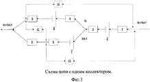
Поддержание нужного потенциала обеспечивается регулированием силы тока, пропускаемого через каждый из коллекторов. Необходимая сила тока при этом определяется эмпирически и зависит от концентрации примесей в электролите и скорости его движения вдоль поверхности коллекторов. Пропускание через коллектор большей силы катодного тока, чем это нужно для восстановления одной из примесей, приводит к смещению потенциала в отрицательную сторону и началу осаждения на коллекторе примеси, имеющей более отрицательный потенциал осаждения. Пропускание силы тока слишком малой величины не обеспечит необходимой очистки электролита от примесей и приведет к осаждению на коллекторах сплавов, обогащенных примесями, которые должны были восстановиться на коллекторах с более положительными потенциалами. Регулирование силы тока осуществляется либо посредством регулировочного сопротивления на участке цепи катод-коллектор, либо посредством источника тока на участке цепи анод-коллектор (см. фиг.1, 2, 3).Maintaining the desired potential is provided by regulating the strength of the current passed through each of the collectors. The required current strength is determined empirically and depends on the concentration of impurities in the electrolyte and its speed along the collector surface. Passing a greater cathode current through the collector than is necessary to restore one of the impurities leads to a negative potential shift and the beginning of deposition of an impurity on the collector, which has a more negative deposition potential. Passing a current of too small a value will not provide the necessary purification of the electrolyte from impurities and will lead to deposition on collectors of alloys enriched in impurities, which should have been restored on collectors with more positive potentials. Regulation of the current is carried out either by adjusting the resistance in the cathode-collector circuit section, or by means of the current source in the cathode-collector circuit section (see Figs. 1, 2, 3).
В отличие от прототипа, в котором не описано каким образом следует выбирать величины потенциала коллекторов и пропускаемого через них тока, в предлагаемом решении регулирование этих параметров может быть выполнено на основании измерения или расчета величины ЭДС между катодом и каждым из коллекторов. Это позволяет устанавливать потенциал и силу тока, которые обеспечивают большую чистоту осаждаемого металла на каждом из коллекторов и большую эффективность очистки электролита.Unlike the prototype, which does not describe how to choose the values of the collector potential and the current passed through them, in the proposed solution, the regulation of these parameters can be performed based on the measurement or calculation of the magnitude of the emf between the cathode and each of the collectors. This allows you to set the potential and current strength, which provide greater purity of the deposited metal on each of the collectors and a greater efficiency of cleaning the electrolyte.
Измерение потенциала коллекторов относительно потенциала катода при подборе силы тока может быть выполнено выключением тока основной цепи электролизера и последующим прямым измерением ЭДС цепи коллектор-катод.The measurement of the potential of the collectors relative to the potential of the cathode when selecting the current strength can be performed by turning off the current of the main circuit of the electrolyzer and subsequent direct measurement of the EMF of the collector-cathode circuit.
Принцип расчета ЭДС цепи коллектор-катод без выключения тока основной цепи описан ниже, в соответствующем разделе.The principle of calculating the EMF of the collector-cathode circuit without turning off the main circuit current is described below in the corresponding section.
В процентном отношении через коллекторы пропускается не более 10% силы тока, проходящего через электролизер.As a percentage, no more than 10% of the current passing through the cell is passed through the collectors.
Коллекторы должны быть изготовлены из материала, который не будет подвергаться анодному окислению или растворению при наложении потенциала восстановления соответствующей примеси. Например, для осаждения меди нельзя использовать коллектор, изготовленный из железа, поскольку железо будет анодно растворяться при потенциале осаждения меди из электролита. В одном из вариантов любой из коллекторов может быть выполнен из того металла, который в соответствии с заданным потенциалом должен в основном восстанавливаться на этом коллекторе. Другими словами, коллектор, на котором будет осаждаться медь, должен быть изготовлен из меди, а для осаждения никеля следует использовать коллектор из никеля и т.д. В другом варианте все коллекторы можно изготавливать из металла, который по потенциалу восстановления равен или положительнее потенциала, устанавливаемого на любом из коллекторов. Например, для осаждения меди, железа и никеля можно использовать коллекторы из меди.Collectors should be made of material that will not undergo anodic oxidation or dissolution when the potential for reduction of the corresponding impurity is imposed. For example, a collector made of iron cannot be used for copper deposition, since iron will dissolve anode at the potential for deposition of copper from the electrolyte. In one embodiment, any of the collectors can be made of that metal, which, in accordance with a given potential, should be mainly restored on this collector. In other words, the collector on which copper will be deposited must be made of copper, and a nickel collector, etc., should be used to deposit nickel. In another embodiment, all the collectors can be made of metal, which in terms of recovery potential is equal to or more positive than the potential set on any of the collectors. For example, copper collectors can be used to deposit copper, iron and nickel.
Для эффективной очистки электролита от примесей коллекторы должны иметь форму, характеризующуюся как можно более развитой поверхностью. Одним из вариантов может быть изготовление коллекторов в виде сетки или решетки с крупной ячейкой (5-50 мм). При меньшем размере ячейки она может быть заблокирована осадком восстановленных примесей, что затруднит циркуляцию электролита сквозь коллектор и снизит эффективность очистки электролита от примесей, что потребует извлечения коллектора из электролита и его очистки от осажденных примесей. Таким образом, выбор формы коллекторов зависит от скорости осаждения примесей на коллекторах, т.е. от чистоты электролита.To effectively clean the electrolyte from impurities, the collectors must have a shape characterized by the most developed surface. One of the options may be the manufacture of collectors in the form of a grid or lattice with a large cell (5-50 mm). With a smaller cell size, it can be blocked by a precipitate of reduced impurities, which will complicate the circulation of the electrolyte through the collector and reduce the efficiency of cleaning the electrolyte from impurities, which will require removing the collector from the electrolyte and cleaning it of the deposited impurities. Thus, the choice of the shape of the collectors depends on the rate of deposition of impurities on the collectors, i.e. from the purity of the electrolyte.
Счищенный с коллекторов металлический осадок представляет собой индивидуальный металл или сплав, обогащенный по одному из элементов, входящих в состав электролита как примесь. Такой осадок может быть подвергнут вторичной переработке после очистки от электролита известными методами.The metal precipitate cleaned from the collectors is an individual metal or alloy enriched in one of the elements that make up the electrolyte as an impurity. Such a precipitate can be recycled after purification from the electrolyte by known methods.
ПРИНЦИП РАСЧЕТА ЭДС ЦЕПИ КАТОД-КОЛЛЕКТОРCALCULATION EMF CALCULATION PRINCIPLE CATHOD-COLLECTOR
Для схемы цепи с одним коллектором (фиг.1) можно записать следующие уравнения:For circuit circuit with a single collector (figure 1), you can write the following equations:


Где известны (измерены) значения:Where the values are known (measured):
I - ток, идущий через ячейку;I is the current flowing through the cell;
Ikk - ток, идущий через коллектор;Ikk - current flowing through the collector;
Uak - напряжение анод-катод;Uak is the voltage of the anode-cathode;
Uakk - напряжение анод-коллектор;Uakk - voltage of the anode-collector;
Ukk - напряжение катод-коллектор.Ukk is the cathode-collector voltage.
Неизвестные величины, которые требуется найти:Unknown quantities to be found:
Ra - сопротивление анода;Ra is the resistance of the anode;
Rk - сопротивление катода;Rk is the cathode resistance;
Rkk - сопротивление коллектора;Rkk - collector resistance;
Re1 - сопротивление электролита между катодом и коллектором;Re 1 is the resistance of the electrolyte between the cathode and the collector;
Re2 - сопротивление электролита между анодом и катодом;Re 2 is the resistance of the electrolyte between the anode and cathode;
Eak - ЭДС анод-катод;Eak - EMF anode-cathode;
Eakk - ЭДС анод - коллектор;Eakk - EMF anode - collector;
Ekk - ЭДС катод-коллектор.Ekk - EMF collector cathode.
Таким образом, в наличии есть система уравнений (1), в которой уравнений меньше, чем неизвестных. Чтобы дополнить ее и найти все неизвестные, можно поступить таким образом. Предполагая, что за небольшой интервал времени (в пределах нескольких минут) ток меняется, получим наборы входных данных:Thus, there is a system of equations (1) in which there are fewer equations than unknowns. To complement it and find all the unknowns, you can do this. Assuming that for a short time interval (within a few minutes) the current changes, we obtain sets of input data:

Обозначим искомые величины через вектор 
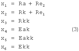
Подставив эти наборы в систему (1) и обозначив искомые величины через вектор
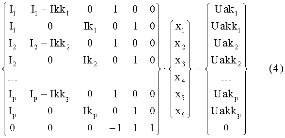
Или в сокращенном виде:Or in abbreviated form:
A·x=b.A x = b.
Матрица А и правая часть составлены из результатов измерений, которые обладают погрешностями измерений. Поэтому систему необходимо решать методом наименьших квадратов, обеспечивающим минимум невязки ||Ax-b||. Для решения задачи применим метод сингулярного разложения. Отметим, что строк в матрице А должно быть не менее 6, то есть числа неизвестных в системе. Следует также отметить, что, чем больше уравнений, то есть количество проведенных измерений, тем точнее получаемое решение.Matrix A and the right side are composed of measurement results that have measurement errors. Therefore, the system must be solved by the least squares method, which ensures a minimum discrepancy || Ax-b ||. To solve the problem, we apply the method of singular decomposition. Note that there must be at least 6 rows in matrix A, that is, the number of unknowns in the system. It should also be noted that, the more equations, that is, the number of measurements taken, the more accurate the resulting solution.
Применив к матрице А процедуру сингулярного разложения [2], получим следующее разложение:Applying the singular decomposition procedure to matrix A [2], we obtain the following decomposition:
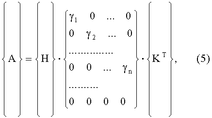
где H, K - ортогональные матрицы, а центральная матрица состоит из диагональных элементов γj, которые называются сингулярными числами, n-ранг матрицы А.where H, K are orthogonal matrices, and the central matrix consists of diagonal elements γ j, which are called singular numbers, the n-rank of matrix A.
Обозначим:Denote:
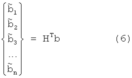
тогда решение будет иметь вид:then the solution will look like:
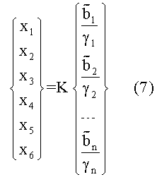
Если все γ1, γ2,…, γn, являющиеся диагональными элементами центральной матрицы в сингулярном разложении (5), отличны от нуля, то система уравнений разрешима и можно однозначно найти все xj по выражению (7). Однако такое решение не всегда корректно, если некоторые γj малы. Для правильного использования метода сингулярного разложения вводится граница, отражающая точность входных данных.If all γ 1 , γ 2 , ..., γ n , which are diagonal elements of the central matrix in the singular expansion (5), are nonzero, then the system of equations is solvable and we can unambiguously find all x j by expression (7). However, such a solution is not always correct if some γ j are small. For the correct use of the method of singular decomposition, a boundary is introduced that reflects the accuracy of the input data.
Любое γj меньшее, чем заданная граница, рассматривается как пренебрежимо малое, и соответствующему выражению 

Заявляемый способ поясняется фиг.1-6The inventive method is illustrated in figures 1-6
На фиг.1 изображена схема цепи с одним коллектором и регулировочным резистором. Ток величиной Ik+Ikk1 подается на анод 1, имеющий сопротивление Ra. Анод соединен последовательно со скачком потенциала 2, равным φα, и с пространством анод - коллектор 3, имеющим сопротивление Re 2. Далее цепь разделяется на две ветки - параллельное соединение.Figure 1 shows a circuit diagram with one collector and an adjustment resistor. A current of Ik + Ikk1 is supplied to
По первой ветке идет ток величиной Ik. Пространство в электролите между катодом и коллектором 4, имеющее сопротивление Re1, соединяется последовательно со скачком потенциала 5, равным φk, и катодом 6, имеющим сопротивление Rk.A current of Ik goes along the first branch. The space in the electrolyte between the cathode and the
По второй ветке проходит ток величиной Ikk1. Скачок потенциала 7, равный φk1, соединен последовательно с коллектором 8, имеющим сопротивление Rkk1, и регулировочным резистором 9, имеющим сопротивление Rom1.A current of Ikk1 passes along the second branch. The
Катод 6 с сопротивлением Rk и резистор 9 с сопротивлением Rom1 подсоединяются к общему участку цепи, и таким образом участок параллельного соединения оказывается пройден, и цепь завершена.The
В приведенной схеме для расчета ЭДС цепи катод-коллектор можно измерить разность потенциалов анод-катод (Uak) 10, разность потенциалов катод-коллектор (Ukk1) 11 и разность потенциалов анод-коллектор (Uakk1) 12.In the above scheme, to calculate the emf of the cathode-collector circuit, the potential difference of the anode-cathode (Uak) 10, the potential difference of the cathode-collector (Ukk1) 11 and the potential difference of the anode-collector (Uakk1) 12 can be measured.
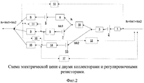
На фиг.2 представлена схема электрической цепи с двумя коллекторами и регулировочными резисторами. Для вычисления ЭДС в данной цепи, в систему, которая рассматривалась выше, необходимо добавить еще одно уравнение. Неизвестных станет больше, количество измерений также будет больше, в остальном же принцип решения не меняется. Опишем отличие представленной на данном рисунке схемы от случая с одним коллектором и одним резистором (фиг.1).Figure 2 presents a diagram of an electrical circuit with two collectors and adjusting resistors. To calculate the EMF in this circuit, one more equation must be added to the system discussed above. There will be more unknowns, the number of measurements will also be larger, otherwise the principle of solution does not change. Let us describe the difference of the circuit shown in this figure from the case with one collector and one resistor (Fig. 1).
В схему цепи добавляется третья ветка, по которой идет ток величиной Ikk2. Скачок потенциала 13, равный φk2, соединен последовательно с коллектором 14, имеющим сопротивление Rkk2, и вторым регулировочным резистором 15, имеющим сопротивление Rom2. В приведенной схеме дополнительно можно измерить разность потенциалов катод - второй коллектор (Ukk2) 16 и разность потенциалов анод - второй коллектор (Uakk2) 17. Также в схему добавляется пространство в электролите между первым и вторым коллектором 18, имеющее сопротивление Re3.A third branch is added to the circuit diagram, along which current Ikk2 flows. A potential jump of 13 equal to φ k2 is connected in series with a
Катод 6 с сопротивлением Rk, резистор 9 с сопротивлением Rom1 и резистор 15 с сопротивлением Rom2 подсоединяются к общему участку цепи и, таким образом, участок параллельного соединения оказывается пройден, и цепь завершена.A
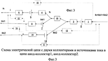
Отличие схемы электрической цепи на фиг.3 от схемы, показанной на фиг.2, заключается в том, что регулировочные резисторы 9 и 15 отсутствуют, вместо этого добавляются источники тока, обеспечивающие разделение тока между тремя ветками: анод-катод, анод-коллектор 1, анод-коллектор 2, соответственно ток делится на три части: Ik, Ikk1, Ikk2.The difference between the circuit of the electric circuit in Fig. 3 and the circuit shown in Fig. 2 is that there are no
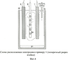
На фиг.4 приведен пример расположения электродов в ячейке согласно схеме на фиг.1, где 19 - система дозирования глинозема; 20 - прутья коллектора; 21- алюминий; 22 - корундовый тигель.Figure 4 shows an example of the location of the electrodes in the cell according to the scheme in figure 1, where 19 is the alumina dosing system; 20 - collector rods; 21- aluminum; 22 - corundum crucible.
Восходящие потоки газа вокруг анода 1 образуют два циркуляционных контура в ячейке. Глинозем растворяется в электролите, попадая в зону интенсивной циркуляции (правый контур). Растворенные примеси переносятся движущимся электролитом от анода 1 в сторону катода 6, как показано стрелками, и осаждаются на сетке коллектора 20, что снижает загрязнение алюминия 21, стекающего с катода.Upward gas flows around the
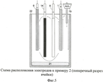
На фиг.5 приведен пример расположения электродов в ячейке согласно схеме на фиг.2. В электролизной ячейке имеется два контура циркуляции электролита. Отличие от схемы расположения электродов на фиг.4 состоит в том, что в междуполюсном пространстве размещены три коллектора, один из которых 8 находится в цепи с первым регулировочным резистором, а два остальных 14 соединены параллельно друг другу в участке цепи со вторым регулировочным резистором. Благодаря этому на одном коллекторе можно поддерживать одно значение ЭДС катод-коллектор 1 (Ekk1), а на двух других коллекторах другое значение ЭДС катод-коллектор 2 (Ekk2) и, следовательно, проводить раздельное осаждение примесей.Figure 5 shows an example of the location of the electrodes in the cell according to the diagram in figure 2. In the electrolysis cell there are two circuits of electrolyte circulation. The difference from the arrangement of the electrodes in figure 4 is that in the interpolar space there are three collectors, one of which 8 is in the circuit with the first regulation resistor, and the other two 14 are connected in parallel to each other in the circuit section with the second regulation resistor. Due to this, on one collector it is possible to maintain one EMF value of cathode-collector 1 (Ekk1), and on two other collectors another value of EMF cathode-collector 2 (Ekk2) and, therefore, to carry out separate deposition of impurities.
На фиг.6 приведены направления конвективных потоков электролита в междуполюсном пространстве ячейки, показанной на Фиг.5. Потоки осуществляют перенос растворенных компонентов анода 1 к коллекторам 8 и 14, а также к катоду 6.Figure 6 shows the directions of convective electrolyte flows in the interpolar space of the cell shown in Figure 5. The streams carry out the transfer of the dissolved components of the
ПРИМЕР 1. ОПИСАНИЕ ЭКСПЕРИМЕНТА С ОДНИМ КОЛЛЕКТОРОМ И РЕЗУЛЬТАТОВ РАСЧЕТА ЭДС КАТОД-КОЛЛЕКТОР.EXAMPLE 1. DESCRIPTION OF THE EXPERIMENT WITH ONE COLLECTOR AND THE RESULTS OF CALCULATION OF EMF CATHOD-COLLECTOR.
Электролиз с инертным металлическим анодом Cu-Ni-Fe и коллектором примесей (растворяющихся компонентов анода) проводили при 900°C в электролите, содержащем 44 NaF, 49 AlF3 и 7 Ak2O3, мас.%. Коллектор 8 в виде сетки 105*125 мм из стали марки Ст3 с размером ячейки 10×10 мм и диаметром прутьев 2 мм соединялся в электрическую цепь, как показано на фиг.1, и погружался вертикально в расплав таким образом, чтобы расстояние от верхней границы сетки до зеркала расплава составляло ~2 см (фиг.4). Металлический анод 1, отлитый из сплава Fe-Ni-Cu, и катод из материала на основе TiB2 6, рабочая (обращенная к коллектору) поверхность которых составляла 90 см2 (h=90 мм; l=100 мм, a=6 мм), устанавливались параллельно сетке коллектора на расстоянии 2 см от нее.Electrolysis with an inert metal anode Cu-Ni-Fe and a collector of impurities (soluble components of the anode) was carried out at 900 ° C in an electrolyte containing 44 NaF, 49 AlF 3 and 7 Ak 2 O 3 , wt.%. The
Через электролизную ячейку пропускали ток величиной 72 А, что в расчете на площадь рабочей поверхности соответствует анодной и катодной плотности тока 0,8 А/см2. Электролиз продолжался непрерывно в течение 76,5 часов. В течение всего времени электролиза в ячейку 22 через автоматический дозатор 19 вводился глинозем.A current of 72 A was passed through the electrolysis cell, which, based on the area of the working surface, corresponds to an anodic and cathodic current density of 0.8 A / cm 2 . Electrolysis continued continuously for 76.5 hours. During the entire time of electrolysis, alumina was introduced into the
Для измерения величины ЭДС Ekk периодически отключался ток и с помощью вольтметра измерялась разность потенциалов между катодом и коллектором. Целевое значение Ekk составляло 0.7 В, что, как следует из приведенного выше описания, обеспечивает выделение на коллекторе каждого из компонентов анодного сплава. Изменяя сопротивление Rom1 на регулировочном резисторе 9, можно изменять значение пропускаемого через коллектор тока и тем самым поддерживать ЭДС цепи катод-коллектор Ekk близким к заданному значению, обеспечивая наиболее полную очистку электролита от примесей без риска перехода в область потенциалов осаждения алюминия. Через 24 часа после начала электролиза для поддержания Ekk приблизительно равным 0,7 В ток в цепи коллектора снизили с 5-6 А до 2-3 А. Таким образом, установившаяся плотность тока на коллекторе составила 15-25 мА/см2, а доля тока, направляемого на выделение примесей, составила 2,7-8,3%, что ниже указанного в описании предела (10%).To measure the EMF value Ekk, the current was periodically switched off and a potential difference between the cathode and collector was measured using a voltmeter. The target value of Ekk was 0.7 V, which, as follows from the above description, ensures the isolation of each of the components of the anode alloy on the collector. By changing the resistance Rom1 on the
Параллельно с измерениями величины Ekk проводили ее расчет по изложенному выше алгоритму расчета ЭДС цепи катод-коллектор. Согласно этому алгоритму для расчета Ekk проводили измерения величин {I, Ikk, Uak и Ukk}. Входные данные и результаты расчетов приведены в таблице 1. Всего в таблице приведено 4 расчета, для каждого из которых было сделано по три последовательных измерения величин {I, Ikk, Uak, Ukk} при изменении силы тока I не более чем на 10 А. Проверку расчетных значений проводили, сравнивая их с измеренными значениями Ekk (изм.). Из таблицы видно, что отклонение измеренного значения Ekk от расчетного составляет не более 50 мВ, что подтверждает возможность использования предложенного алгоритма для поддержания ЭДС катод-коллектор в оптимальном диапазоне значений без отключения тока на электролизере.In parallel with the measurements of Ekk, its calculation was carried out according to the above algorithm for calculating the emf of the cathode-collector circuit. According to this algorithm, for calculating Ekk, we measured {I, Ikk, Uak, and Ukk}. The input data and calculation results are shown in Table 1. In total, 4 calculations are given in the table, for each of which three consecutive measurements of {I, Ikk, Uak, Ukk} values were made when the current I changed by no more than 10 A. Check calculated values were carried out by comparing them with the measured Ekk values (meas.). It can be seen from the table that the deviation of the measured Ekk value from the calculated value is no more than 50 mV, which confirms the possibility of using the proposed algorithm to maintain the cathode-collector EMF in the optimal range of values without turning off the current on the cell.
Отметим, что хотя описанные измерения и расчеты были сделаны на ячейке с одним коллектором, принцип расчета может быть распространен и на случаи с несколькими коллекторами с различными потенциалами на них.Note that although the described measurements and calculations were made on a cell with one collector, the principle of calculation can be extended to cases with several collectors with different potentials on them.
По окончании эксперимента взвешивание катодного алюминия 21 показало, что выход алюминия по току составил 55%. Чистота катодного алюминия составила 98.5%. Осадок на коллекторе без учета компонентов электролита и примесей, не входящих в состав анода (Si, Ti, Cr, Zn, S, в сумме менее 5%), имел следующий состав: 29,7 Fe, 7,9 Ni, 60,5 Cu (мас.%), что близко к составу анодного сплава и говорит о практически полном осаждении на коллекторе растворенных в расплаве компонентов анода.At the end of the experiment, weighing the
ПРИМЕР 2. ОПИСАНИЕ ЭКСПЕРИМЕНТА С РАЗДЕЛЬНЫМ ОСАЖДЕНИЕМ МЕДИ И ДРУГИХ ПРИМЕСЕЙEXAMPLE 2. DESCRIPTION OF THE EXPERIMENT WITH SEPARATE DEPOSITION OF COPPER AND OTHER IMPURITIES
В эксперименте использовали ячейку с тремя цилиндрическими электродами-коллекторами. Схема расположения электродов в ячейке приведена на фиг.5, 6. С целью максимальной степени очистки расплава от растворенных компонентов анода и предотвращения их осаждения на катоде коллекторы располагали между анодом и катодом на траектории движения электролита от анода к катоду. Все коллекторы представляли собой цилиндрические стержни высотой 110 мм и диаметром 10 мм, приваренные к стальным токоподводам, которые были защищены алундовыми чехлами. Глубина погружения коллекторов в электролит составляла около 120 см. Состав электролита, температура электролиза, материал и размеры анода и катода были аналогичными тем, что описаны в примере 1. Сила тока на электролизной ячейке поддерживалась равной 61 А. Схема полной цепи показана на фиг.2. В качестве коллектора 8 служил медный стержень, а в качестве коллектора 14 - два параллельно соединенных никелевых стержня. Для осаждения меди на медном коллекторе 8 поддерживали ЭДС катод-коллектор1 (Ekk1) около 1,7 В. На двух никелевых коллекторах 14 поддерживали ЭДС катод-коллектор2 (Ekk2) около 0,9 В для осаждения обогащенного по никелю и железу сплава Cu-Ni-Fe. Причиной увеличения площади коллектора 14 относительно коллектора 8, очевидно, является большее количество примесей, осаждаемых при ЭДС катод-коллектор 2 около 0,9 В. Текущие значения Ekk1 и Ekk2 определяли прямым измерением при отключении тока электролиза. Регулировку силы тока, пропускаемого через коллектора 8 и 14, и тем самым поддержание Ekk1 и Ekk2 вблизи целевых значений, производили путем изменения сопротивлений Rom1 и Rom2 на регулировочных резисторах 9 и 15, соответственно.In the experiment, a cell with three cylindrical collector electrodes was used. The layout of the electrodes in the cell is shown in FIGS. 5, 6. In order to maximize the degree of purification of the melt from the dissolved components of the anode and to prevent their deposition on the cathode, collectors were placed between the anode and cathode on the electrolyte from the anode to the cathode. All collectors were cylindrical rods 110 mm high and 10 mm in diameter, welded to steel current leads, which were protected by alundum covers. The immersion depth of the collectors in the electrolyte was about 120 cm. The electrolyte composition, electrolysis temperature, material and dimensions of the anode and cathode were similar to those described in example 1. The current strength on the electrolysis cell was maintained equal to 61 A. The full circuit diagram is shown in figure 2 . A copper rod served as
Через 50 часов электролиза токи на коллекторах приблизились к своим стационарным значениям, т.е. для поддержания Ekk1 и Ekk2 вблизи целевых значений больше не требовалось проводить регулировку сопротивлений Rom1 и Rom2 с помощью резисторов 9 и 15. На медном коллекторе 8 стационарное значение тока составило около 0.5 А (~15 мА/см2), на никелевых коллекторах 14 около 4 А (~60 мА/см2). Доля суммарного тока, направляемого на выделение примесей, составила около 7,5%, что ниже указанного в описании предела (10%).After 50 hours of electrolysis, the currents on the collectors approached their stationary values, i.e. To maintain Ekk1 and Ekk2 near the target values, it was no longer necessary to adjust the resistances Rom1 and
По истечении 100 часов электролиз был остановлен. Масса полученного алюминия составила 1050 г, что соответствует выходу по току около 51%. Полученный алюминий имел чистоту 98.7%. Как и в результате эксперимента, описанного в примере 1, осадки на коллекторах обладали пористой структурой и были пропитаны электролитом. В осадке, полученном на медном коллекторе 8 без учета компонентов электролита и примесей, не входящих в состав анода (Si, Ti, Cr, Zn, S, в сумме менее 5%), содержалось 97,3 Cu, 0,2 Fe, 2,5 Ni (мас.%). Осадок на никелевых коллекторах 14 содержал в среднем 37 Cu, 35,5 Fe, 27,5 Ni (мас.%).After 100 hours, electrolysis was stopped. The mass of aluminum obtained was 1050 g, which corresponds to a current efficiency of about 51%. The resulting aluminum had a purity of 98.7%. As in the experiment described in example 1, the deposits on the reservoirs had a porous structure and were impregnated with electrolyte. The precipitate obtained on
Полученные результаты демонстрируют возможность ведения электролиза с раздельным осаждением элементов на коллекторах путем поддержания соответствующих значений ЭДС катод-коллектор. Более полное разделение примесей может быть достигнуто путем более оптимального расположения коллекторов в электролизере.The obtained results demonstrate the possibility of conducting electrolysis with separate deposition of elements on the collectors by maintaining the corresponding values of the EMF cathode-collector. A more complete separation of impurities can be achieved by a more optimal arrangement of the collectors in the cell.
Список литературыBibliography
1. Антипов Е.В. Электрохимическое поведение металлов и бинарных сплавов в криолит-глиноземных расплавах / Антипов Е.В., Борзенко А.Г., Денисов В.М., Филатов А.Ю., Иванов В.В., Казаков С.М., Мазин П.М., Мазин В.М., Штанов В.И., Симаков Д.А., Цирлина Г.А., Васильев С.Ю., Великодный Ю.А. // Light Metals. - 2006. - С.403-408.1. Antipov EV Electrochemical behavior of metals and binary alloys in cryolite-alumina melts / Antipov E.V., Borzenko A.G., Denisov V.M., Filatov A.Yu., Ivanov V.V., Kazakov S.M., Mazin P .M., Mazin V.M., Shtanov V.I., Simakov D.A., Tsirlina G.A., Vasiliev S.Yu., Velikodny Yu.A. // Light Metals. - 2006. - S.403-408.
2. Лоусон Ч., Хенсон Р., Численное решение задач метода наименьших квадратов, М.: Наука, 1986 г., 232 с.2. Lawson, Ch., Henson, R., Numerical Solution of the Least Squares Method, Moscow: Nauka, 1986, 232 pp.
Claims (7)
Priority Applications (1)
| Application Number | Priority Date | Filing Date | Title |
|---|---|---|---|
| RU2009142104/02A RU2425177C1 (en) | 2009-11-16 | 2009-11-16 | Method of electrolytic production of metals with simultaneous deposition of admixtures |
Applications Claiming Priority (1)
| Application Number | Priority Date | Filing Date | Title |
|---|---|---|---|
| RU2009142104/02A RU2425177C1 (en) | 2009-11-16 | 2009-11-16 | Method of electrolytic production of metals with simultaneous deposition of admixtures |
Publications (2)
| Publication Number | Publication Date |
|---|---|
| RU2009142104A RU2009142104A (en) | 2011-05-27 |
| RU2425177C1 true RU2425177C1 (en) | 2011-07-27 |
Family
ID=44734317
Family Applications (1)
| Application Number | Title | Priority Date | Filing Date |
|---|---|---|---|
| RU2009142104/02A RU2425177C1 (en) | 2009-11-16 | 2009-11-16 | Method of electrolytic production of metals with simultaneous deposition of admixtures |
Country Status (1)
| Country | Link |
|---|---|
| RU (1) | RU2425177C1 (en) |
Cited By (3)
| Publication number | Priority date | Publication date | Assignee | Title |
|---|---|---|---|---|
| RU2522920C1 (en) * | 2013-04-04 | 2014-07-20 | Федеральное государственное бюджетное учреждение науки Институт высокотемпературной электрохимии Уральского отделения Российской Академии наук | Electrolytic cell for fine-ply electrolytic refining of metal lead |
| RU2558316C2 (en) * | 2013-03-20 | 2015-07-27 | Общество с ограниченной ответственностью "Легкие металлы" | Method and device for aluminium affinage |
| RU2702672C1 (en) * | 2018-10-29 | 2019-10-10 | Общество с ограниченной ответственностью "Легкие металлы" | Method of producing aluminum of high purity by electrolysis of molten salts |
Citations (4)
| Publication number | Priority date | Publication date | Assignee | Title |
|---|---|---|---|---|
| US4115215A (en) * | 1976-09-22 | 1978-09-19 | Aluminum Company Of America | Aluminum purification |
| SU1291617A1 (en) * | 1984-12-05 | 1987-02-23 | Иркутский Филиал Всесоюзного Научно-Исследовательского И Проектного Института Алюминиевой,Магниевой И Электродной Промышленности | Method and apparatus for refining aluminium alloys |
| US20060185984A1 (en) * | 2003-08-14 | 2006-08-24 | Nguyen Thinh T | Metal electrowinning cell with electrolyte purifier |
| WO2009007440A2 (en) * | 2007-07-12 | 2009-01-15 | Basf Se | Process for the electrochemical purification of aluminium |
-
2009
- 2009-11-16 RU RU2009142104/02A patent/RU2425177C1/en not_active IP Right Cessation
Patent Citations (4)
| Publication number | Priority date | Publication date | Assignee | Title |
|---|---|---|---|---|
| US4115215A (en) * | 1976-09-22 | 1978-09-19 | Aluminum Company Of America | Aluminum purification |
| SU1291617A1 (en) * | 1984-12-05 | 1987-02-23 | Иркутский Филиал Всесоюзного Научно-Исследовательского И Проектного Института Алюминиевой,Магниевой И Электродной Промышленности | Method and apparatus for refining aluminium alloys |
| US20060185984A1 (en) * | 2003-08-14 | 2006-08-24 | Nguyen Thinh T | Metal electrowinning cell with electrolyte purifier |
| WO2009007440A2 (en) * | 2007-07-12 | 2009-01-15 | Basf Se | Process for the electrochemical purification of aluminium |
Cited By (3)
| Publication number | Priority date | Publication date | Assignee | Title |
|---|---|---|---|---|
| RU2558316C2 (en) * | 2013-03-20 | 2015-07-27 | Общество с ограниченной ответственностью "Легкие металлы" | Method and device for aluminium affinage |
| RU2522920C1 (en) * | 2013-04-04 | 2014-07-20 | Федеральное государственное бюджетное учреждение науки Институт высокотемпературной электрохимии Уральского отделения Российской Академии наук | Electrolytic cell for fine-ply electrolytic refining of metal lead |
| RU2702672C1 (en) * | 2018-10-29 | 2019-10-10 | Общество с ограниченной ответственностью "Легкие металлы" | Method of producing aluminum of high purity by electrolysis of molten salts |
Also Published As
| Publication number | Publication date |
|---|---|
| RU2009142104A (en) | 2011-05-27 |
Similar Documents
| Publication | Publication Date | Title |
|---|---|---|
| CA2860813C (en) | System for power control in cells for electrolytic recovery of a metal | |
| JP5791083B2 (en) | Primary production of elemental materials | |
| WO2004104273A1 (en) | Cu-ni-fe anode for use in aluminum producing electrolytic cell | |
| KR100840163B1 (en) | Improvement of Current Efficiency in Electrolysis | |
| JP2014533778A (en) | Process for industrial copper electrorefining | |
| Moskalyk et al. | Anode effects in electrowinning | |
| AU2004265508B2 (en) | Metal electrowinning cell with electrolyte purifier | |
| SE447136B (en) | RABLY ELECTRIC REFINING PROCEDURE AND APPLICATION PROCEDURE | |
| DK181867B1 (en) | Removing impurities from an electrolyte | |
| RU2009142104A (en) | METHOD FOR ELECTROLYTIC PRODUCTION OF METALS AT SIMULTANEOUS DEPOSITION OF IMPURITIES | |
| JP7271917B2 (en) | Copper electrolytic refining method | |
| RU2553319C1 (en) | Method of metal powder manufacturing by electrolysis | |
| RU2458189C1 (en) | Electrolyte to apply coatings on electroconductive and non-electroconductive materials | |
| Monev et al. | In situ stress measurements during electrodeposition of Ag-Sb and Pt-Co alloy multilayers | |
| JP7334095B2 (en) | Tin electrowinning method | |
| US2532629A (en) | Method of electrodepositing iron | |
| Pajdowski | The influence of anode passivation on the quality and structure of cathode copper | |
| SU186705A1 (en) | BIPOLAR ELECTROLISER OF THE BOX TYPE | |
| Smith | Electrorefining Copper at High Current Densities | |
| JP2013040368A (en) | Operating method of lead electrorefining equipment | |
| JP2014114496A (en) | Structure and method of producing the same | |
| Koyama et al. | Smooth Electrodeposits of Molybdenum from KF-B2O3-Li2MoO4 Melt | |
| PL112701B1 (en) | Process for eyectrolytic manufacturing of non-ferrous metals in the form of band and apparatus therefor |
Legal Events
| Date | Code | Title | Description |
|---|---|---|---|
| MM4A | The patent is invalid due to non-payment of fees |
Effective date: 20181117 |