RU2425198C2 - Method of making parquet floors - Google Patents
Method of making parquet floors Download PDFInfo
- Publication number
- RU2425198C2 RU2425198C2 RU2010105131/03A RU2010105131A RU2425198C2 RU 2425198 C2 RU2425198 C2 RU 2425198C2 RU 2010105131/03 A RU2010105131/03 A RU 2010105131/03A RU 2010105131 A RU2010105131 A RU 2010105131A RU 2425198 C2 RU2425198 C2 RU 2425198C2
- Authority
- RU
- Russia
- Prior art keywords
- plywood
- parquet
- sheets
- sheet
- mounting
- Prior art date
Links
Images



Landscapes
- Floor Finish (AREA)
Abstract
Description
Изобретение относится к строительству, а именно к созданию паркетных полов на фанерном основании.The invention relates to the construction, namely the creation of parquet floors on a plywood base.
Современные паркетные полы представляют собой многослойную конструкцию (Теличко А.А. Паркетные работы, М.: Рипол Классик, 2003, стр.122-124), каждый слой которой выполняет определенную функцию и является основанием для вышележащего слоя.Modern parquet floors are a multi-layer structure (Telichko A.A. Parquet works, M .: Ripol Classic, 2003, pp. 122-124), each layer of which performs a certain function and is the basis for the overlying layer.
Количество и назначение слоев определяют исходя из конкретных условий эксплуатации, при этом четыре слоя всегда входят в состав конструкции паркетного пола по фанерному основанию. Рассмотрим их с учетом того, что в справочном приложении №3 СНиП 3.04.01-87 «Изоляционные и отделочные покрытия» приведены следующие определения слоев: «покрытие» - верхний эксплуатационный слой; «прослойка» - промежуточный слой пола, связывающий покрытие с нижележащим слоем; «стяжка» - (основание под покрытие) - слой пола, служащий для выравнивания поверхности нижележащего слоя пола или перекрытия. Далее будем использовать приведенные термины для элементов конструкции паркетного пола следующим образом.The number and purpose of the layers is determined on the basis of specific operating conditions, while four layers are always included in the structure of the parquet floor on a plywood base. Consider them taking into account the fact that in the reference application No. 3 of SNiP 3.04.01-87 “Insulating and finishing coatings” the following definitions of layers are given: “coating” - the upper operational layer; “Interlayer” - an intermediate layer of the floor connecting the coating with the underlying layer; “Screed” - (base for covering) - floor layer used to level the surface of the underlying floor layer or floor. Next, we will use the above terms for structural elements of the parquet floor as follows.
Первый нижний слой 1 (фиг.1) является силовым несущим основанием или перекрытием, предназначенным для восприятия всех возможных нагрузок в процессе строительства и эксплуатации здания. Расположенный на нем слой 2 (фиг.1) является формирующим основанием, которое задает пространственное положение паркетного покрытия в соответствии с проектом и обеспечивает при этом переход от грубой поверхности силового основания к ровной поверхности формирующего основания с нормированными геометрическими характеристиками. Следующий слой 3 (фиг.1) является чистовым основанием или прослойкой и предназначен для непосредственного размещения и крепления на нем паркетных планок, модулей, розеток и других паркетных элементов. Совокупность всех паркетных элементов, укрепленных на чистовом основании, образует последний верхний слой 4 (фиг.1), который и является собственно паркетным покрытием.The first lower layer 1 (Fig. 1) is a power supporting base or floor designed to absorb all possible loads during the construction and operation of the building. The
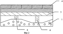
Создание паркетного пола начинают с чистового основания, которое формируют из отдельных модулей, выполненных, например, из фанеры. Фанерные модули укладывают на формирующее основание 2 (фиг.1), которое может быть выполнено в виде «чернового пола 5 (фиг.2) по лагам 6 (фиг.2) или в виде монолитной стяжки 7 (фиг.3), что определяет особенности конструкции фанерных модулей для каждого приведенного варианта.The creation of the parquet floor begins with a finishing base, which is formed from individual modules made, for example, of plywood. Plywood modules are laid on the forming base 2 (Fig. 1), which can be made in the form of a "rough floor 5 (Fig. 2) along the lags 6 (Fig. 2) or in the form of a monolithic screed 7 (Fig. 3), which determines design features of plywood modules for each given option.
Так для формирующего основания в виде «чернового пола по лагам» используют готовые фанерные листы стандартного размера, в которых выполняют крепежные отверстия под саморезы для монтажа на деревянную конструкцию этого основания фиг.2.So for the forming base in the form of a "rough floor on the logs" use ready-made plywood sheets of standard size, in which fastening holes are made for self-tapping screws for mounting on the wooden structure of this base, Fig.2.
Для формирующего основания в виде монолитной стяжки используют специально отформатированные монтажные листы фанеры с размером от 40×40 см до 75×75 см (М.Ю.Сорочкин, «Все, что вы хотели знать о паркете», М.: Изд. дом, «Юность», 2005, стр.56), в которых также выполняют крепежные отверстия под саморезы для монтажа на стяжку с использованием дюбелей. При этом на стяжку предварительно наносят клей, а затем укладывают монтажные листы и притягивают их саморезами таким образом, чтобы они плотно и без пустот прилегали к этому основанию (фиг.3).For the forming base in the form of a monolithic screed, specially formatted plywood mounting sheets with sizes from 40 × 40 cm to 75 × 75 cm are used (M.Yu. Sorochkin, “Everything You Wanted to Know about Parquet”, M .: Publishing House, “Youth”, 2005, p. 56), in which mounting holes are also made for self-tapping screws for mounting on a screed using dowels. In this case, glue is preliminarily applied to the screed, and then mounting sheets are laid and they are attracted with self-tapping screws so that they fit snugly and without voids to this base (Fig. 3).
Выполнение всех последующих операций не зависит от используемой конструкции формирующего основания, а на поверхности полученного чистового фанерного основания проводят выявление недопустимых неровностей, которые удаляют, а затем производят окончательную циклевку для получения ровной поверхности под паркет.The execution of all subsequent operations does not depend on the used design of the forming base, and on the surface of the resulting finishing plywood base, unacceptable irregularities are removed that are removed and then final scraping is done to obtain a flat surface under the parquet.
Далее на фанерное основание приклеивают паркетные элементы и крепят их с помощью гвоздей таким образом, чтобы они плотно и без пустот прилегали к этому основанию. На полученном паркетном покрытии также выявляют и удаляют недопустимые неровности, а затем это покрытие циклюют и шлифуют до получения ровной поверхности под защитно-декоративное покрытие.Next, parquet elements are glued to the plywood base and fastened with nails in such a way that they fit snugly and without voids to this base. On the resulting parquet coating, unacceptable irregularities are also detected and removed, and then this coating is cycled and ground until a smooth surface is obtained under the protective and decorative coating.
Готовый паркетный пол должен отвечать требованиям действующих нормативных документов. Так, в соответствии с пунктом 4.43 СНиП 3.04.01-87 «Изоляционные и отделочные покрытия», отклонения поверхности паркетного покрытия от плоскости при проверке контрольной двухметровой рейкой не должны превышать 2 мм.The finished parquet floor must meet the requirements of current regulatory documents. So, in accordance with paragraph 4.43 of SNiP 3.04.01-87 “Insulating and finishing coatings”, the deviations of the surface of the parquet coating from the plane when checking with a control two-meter rail should not exceed 2 mm.
За прототип принят способ по книге Б.К.Алинина «Паркетные полы», М.: Аделант, 2004, который состоит в том, что чистовое фанерное основание укладывают с учетом конструкции формирующего основания, а именно на монолитную стяжку крепят монтажные листы фанеры квадратной формы с размером 50×50 см или 40×40 см, а на формирующее основание в виде «чернового пола по лагам» крепят готовые листы фанеры стандартного размера. На поверхности полученного чистового фанерного основания выполняют ручное выявление недопустимых неровностей с помощью строительного двухметрового уровня. Места расположения неровностей обозначают на обследуемой поверхности рисованными индикаторными линиями, которые служат ориентиром для последующего их удаления. Это удаление выполняют путем местного сошлифовывания, после чего выполняют контрольное выявление недопустимых неровностей, результатом которого может быть нанесение индикаторных линий вновь для продолжения удаления еще сохранившихся неровностей. Затем на полученном чистовом фанерном основании выполняют укладку паркетных планок, модулей, розеток и других паркетных элементов в паркетное покрытие, поверхность которого также подвергают ручному выявлению и полному удалению недопустимых неровностей, затем выполняют циклевку, шлифовку и другие финишные операции и наносят защитно-декоративное покрытие.The method according to the book by B.K. Alinin “Parquet floors”, M .: Adelant, 2004, which consists in laying a clean plywood base taking into account the design of the forming base, namely, on a monolithic screed, mounting plates of square plywood, is adopted as a prototype with a size of 50 × 50 cm or 40 × 40 cm, and on the forming base in the form of a “rough floor on the logs”, ready-made plywood sheets of a standard size are attached. On the surface of the resulting finishing plywood base, manual detection of unacceptable bumps is performed using a two-meter level construction. The locations of irregularities are indicated on the surface under examination by drawn indicator lines, which serve as a guide for their subsequent removal. This removal is carried out by local grinding, after which the control detection of unacceptable irregularities is carried out, the result of which may be the application of indicator lines again to continue the removal of the remaining irregularities. Then, on the resulting finishing plywood base, parquet strips, modules, sockets and other parquet elements are laid in a parquet coating, the surface of which is also subjected to manual identification and the complete removal of unacceptable irregularities, then looping, grinding and other finishing operations are performed and a protective and decorative coating is applied.
Признаками прототипа являются - укладка и крепление фанеры на «черновой пол по лагам» в качестве чистового основания под паркет, укладка и крепление фанеры на монолитную стяжку в качестве чистового основания под паркет, выявление и удаление недопустимых неровностей на поверхности чистового фанерного основания, укладка паркетных элементов в паркетное покрытие на чистовое фанерное основание, выявление и удаление недопустимых неровностей на поверхности паркетного покрытия.Signs of the prototype are - laying and fixing plywood on the “sub-floor on logs” as a finishing base for parquet, laying and fixing plywood on a monolithic screed as a finishing base for parquet, identifying and removing unacceptable irregularities on the surface of a finishing plywood base, laying parquet elements in the parquet coating on a clean plywood base, the identification and removal of unacceptable irregularities on the surface of the parquet coating.
Принятый за прототип способ имеет ряд недостатков, таких как высокая трудоемкость изготовления и крепления монтажных фанерных листов к существующей стяжке, высокая трудоемкость первичного и повторного ручного выявления и удаления недопустимых неровностей на поверхности чистового фанерного основания и поверхности готового паркетного покрытия в соответствии с требованиями действующих нормативных документов (СНиП 3.04.01-87).The method adopted for the prototype has several disadvantages, such as the high complexity of manufacturing and attaching mounting plywood sheets to an existing screed, the high complexity of the initial and repeated manual detection and removal of unacceptable irregularities on the surface of the finished plywood base and the surface of the finished parquet coating in accordance with the requirements of current regulatory documents (SNiP 3.04.01-87).
Трудоемкость изготовления состоит в том, что монтажные листы в виде квадратов с размерами 50×50 см получают из стандартного фанерного листа 1,5×1,5 м путем распиловки его на девять частей, а листы с размером 40×40 см получают из стандартного листа размером 2,4×1,2 м путем распиловки на 18 частей. В первом случае, например, операцию распиловки необходимо выполнить 8 раз, из них два распила выполняют на целом листе, затем еще по два на каждой полученной части листа, а во втором 17 раз, из которых пять распилов выполняют на целом листе, а затем по два распила на каждой из шести полученных частей листа. Перед укладкой на формирующее основание в них сверлят крепежные отверстия по следующей схеме. Четыре отверстия выполняют по углам листа и еще по два промежуточных отверстия вдоль каждой диагонали листа.The complexity of manufacturing consists in the fact that assembly sheets in the form of squares with dimensions of 50 × 50 cm are obtained from a standard plywood sheet of 1.5 × 1.5 m by sawing it into nine parts, and sheets with a size of 40 × 40 cm are obtained from a standard sheet 2.4 × 1.2 m in size by sawing into 18 parts. In the first case, for example, the sawing operation must be performed 8 times, of which two cuts are performed on the whole sheet, then two more on each received part of the sheet, and in the second 17 times, of which five cuts are performed on the whole sheet, and then each two cuts on each of the six received parts of the sheet. Before laying on the forming base, drilling holes are drilled in them according to the following scheme. Four holes are made at the corners of the sheet and two more intermediate holes along each diagonal of the sheet.
Распиловку фанеры на монтажные листы квадратной формы выполняют как на объекте, так и вне него в производственных условиях. Основной недостаток первого варианта состоит в трудности ручной доставки крупногабаритных стандартных листов фанеры внутри здания к месту укладки, особенно в случае отсутствия грузового лифта. Недостаток второго варианта состоит в том, что форма и слишком малый размер монтажных листов приводят к необходимости многократного выполнения ручного переноса этих листов.Sawing plywood into square-shaped mounting plates is performed both on-site and off-site under production conditions. The main disadvantage of the first option is the difficulty in manually delivering large standard plywood sheets inside the building to the installation site, especially in the absence of a freight elevator. The disadvantage of the second option is that the shape and too small size of the mounting sheets lead to the need for multiple manual transfer of these sheets.
Трудоемкость процесса крепления монтажных листов фанеры состоит в том, что после укладки листов фанеры на подготовленную стяжку с нанесенным клеем, через крепежные отверстия этих листов, в стяжке сверлят крепежные отверстия под дюбель. В полученное отверстие через фанеру забивают дюбель, затем в него устанавливают саморез, добивают эту систему так, чтобы дюбель прошел фанеру и полностью вошел в стяжку. Затем завинчивают саморезы с моментом, достаточным для плотного притягивания фанеры к монолитному основанию.The complexity of the process of attaching plywood mounting sheets is that after laying the plywood sheets on the prepared screed with adhesive, through the mounting holes of these sheets, the mounting holes for the dowel are drilled in the screed. A dowel is driven into the hole obtained through plywood, then a self-tapping screw is installed in it, they finish this system so that the dowel passes through the plywood and completely enters the screed. Then screw the screws with a moment sufficient to tightly attract the plywood to the monolithic base.
Следует отметить недостаток такого крепления. После завинчивания самореза его головка несколько утапливается в фанеру, что позволяет абразивной ленте на этапе циклевки фанеры проходить над саморезом, не задевая его. Но это выполняется только при малых неровностях. Значительные неровности требуют соответствующего по толщине удаления слоя фанеры, при этом абразивная лента может наезжать на головку самореза, что не позволяет достичь требуемого выравнивания, а в худшем случае может привести к повреждению абразивной ленты и барабана шлифовальной машины. Такие саморезы необходимо удалять, но не всегда их можно выявить заранее. Поэтому при циклевке необходимо соблюдать повышенное внимание для своевремнного обнаружения и последующего удаления опасно расположенных саморезов. Все это повышает трудоемкость процесса циклевки и увеличивает время на ее выполнение.It should be noted the disadvantage of such a mount. After screwing the self-tapping screw, its head is somewhat recessed into the plywood, which allows the abrasive tape to pass over the self-tapping screw at the plywood scraping stage without touching it. But this is only possible with small irregularities. Significant irregularities require the removal of a plywood layer corresponding to the thickness, while the abrasive tape can run into the head of the self-tapping screw, which does not allow to achieve the required alignment, and in the worst case, can damage the abrasive tape and the grinder drum. Such screws must be removed, but they can not always be identified in advance. Therefore, when looping, it is necessary to observe increased attention for the timely detection and subsequent removal of dangerously located self-tapping screws. All this increases the complexity of the looping process and increases the time to complete it.
Названный недостаток проявляется таким же образом и при креплении фанеры на основание в виде «чернового пола по лагам».The aforementioned drawback is manifested in the same way when plywood is fixed to the base in the form of a “rough floor in logs”.
Кроме того, с момента укладки монтажного листа на стяжку и до завершения процесса завинчивания всех саморезов на нем клей выдавливается через открытые монтажные отверстия на поверхность листа и загрязняет его. Эти загрязнения необходимо удалять, не допуская их засыхания, что может затруднить процесс циклевки, но важнее другое обстоятельство. При таком процессе укладки, в случае использования двухкомпонентного клея, не представляется возможным приступать к укладке очередного монтажного листа до полного закрепления предыдущего листа по всем крепежным отверстиям, то есть до того момента, когда саморезы закроют монтажные отверстия и тем самым перекроют доступ клея на поверхность фанерного листа. Завинчивание саморезов начинают выполнять сразу же после укладки каждого монтажного листа на стяжку, чтобы уменьшить количество клея, попадающего на поверхность, и позволить проход по свежеуложенному листу для выполнения операций укладки и крепления очередного листа. На это уходит значительное время, а так как время жизни двухкомпонентного клея ограничено примерно одним часом, то не удается использовать полностью весь клей, приготовленный из одной порции компонентов заводской дозировки. Поэтому производят приготовление меньшего количества клея, что является нарушением технологического процесса, так как в этом случае заводские порции каждого компонента делят для смешивания приблизительно - «на глаз», при этом сам процесс укладки и крепления монтажных листов требует еще большего времени. Это определяется тем, что необходимо дополнительное время как на выполнение самого процесса деления на части, так и на выполнение процесса смешивания для каждой полученной части.In addition, from the moment the installation sheet is laid on the screed and until the screwing process is completed, all glue is squeezed on it through open mounting holes on the surface of the sheet and contaminates it. These contaminants must be removed, preventing them from drying out, which can complicate the process of hitching, but another circumstance is more important. With this installation process, in the case of using two-component glue, it is not possible to start laying the next mounting sheet until the previous sheet is completely fixed to all the mounting holes, that is, until the screws cover the mounting holes and thereby block the access of the adhesive to the plywood surface sheet. They begin to tighten the screws immediately after laying each mounting sheet on the screed to reduce the amount of glue falling on the surface and allow passage through the freshly laid sheet to perform stacking and fastening of the next sheet. This takes considerable time, and since the life time of a two-component adhesive is limited to about one hour, it is not possible to use all of the adhesive prepared from one portion of the factory dosage components completely. Therefore, a smaller amount of glue is prepared, which is a violation of the technological process, since in this case the factory portions of each component are divided approximately - “by eye” for mixing, while the process of laying and attaching mounting sheets requires even more time. This is determined by the fact that additional time is required both for the implementation of the process of dividing into parts, and for the execution of the mixing process for each part received.
После завинчивания всех саморезов на каждом листе проверяют монолитность полученной системы путем простукивания для выявления пустот под фанерным основанием.After screwing all the screws on each sheet, the solidity of the resulting system is checked by tapping to identify voids under the plywood base.
Наличие таких пустот ведет к ослаблению конструкции пола, поэтому предпринимают меры для их устранения. Для этого, в местах обнаружения пустот, устанавливают дополнительные саморезы для локального притягивания фанеры. А если это не дает желаемый результат, то вывинчивают все саморезы, поднимают лист фанеры и дополнительно наносят клей в тех местах, где его не хватает. Фанеру крепят на прежнее место и вновь проверяют монолитность по всей поверхности листа. Все это повышает трудоемкость процесса укладки и крепления монтажных листов и увеличивает время на его выполнение.The presence of such voids leads to a weakening of the floor structure, therefore, measures are being taken to eliminate them. For this, in the places where voids are detected, additional self-tapping screws are installed for the local attraction of plywood. And if this does not give the desired result, then unscrew all the screws, lift the plywood sheet and additionally apply glue in those places where it is not enough. The plywood is fixed in its original place and again monolithic is checked over the entire surface of the sheet. All this increases the complexity of the installation process and mounting sheets and increases the time for its implementation.
Далее проводят выявление недопустимых неровностей на поверхности фанерного основания в соответствии с нормативными требованиями.Next, they identify unacceptable bumps on the surface of the plywood base in accordance with regulatory requirements.
Высокая трудоемкость работ по проверке выполнения нормативных требований к геометрическим параметрам поверхности паркетного пола и к его промежуточным слоям объясняется как их высокими требованиями, так и ограниченным набором средств и методов для их достижения. Все эти работы сводятся к ручному выявлению и ручному обозначению выявленных участков превышения предельно допускаемых значений неровностей на обследуемой поверхности. Основным средством контроля геометрических параметров стяжки, фанерного основания и собственно паркетного пола является большой реечный строительный уровень (длина 2 м), а для обозначения участков с недопустимыми неровностями на обследуемой поверхности используют строительный карандаш.The high complexity of the work to verify compliance with the regulatory requirements for the geometric parameters of the surface of the parquet floor and its intermediate layers is explained both by their high requirements and by a limited set of tools and methods to achieve them. All these works are reduced to the manual identification and manual designation of the identified areas of exceeding the maximum permissible values of irregularities on the examined surface. The main means of controlling the geometric parameters of the screed, plywood base and the parquet floor itself is a large rack construction level (2 m long), and a construction pencil is used to mark areas with unacceptable irregularities on the surface being examined.
Следует отметить, что СНиП 3.04.01-87 по п.4.43 «Требования к готовому покрытию пола» и по п.4.24 «Требования к промежуточным элементам пола» предъявляет одинаковые требования к готовому паркету, промежуточному фанерному основанию и к стяжке, а это значит, что в отдельных областях обследуемой поверхности возможно такое сочетание разнонаправленных предельно допускаемых отклонений от плоскости стяжки, что после установки и закрепления фанеры названные отклонения в этих местах будут переходить на поверхность фанеры с некоторым увеличением. Поэтому даже полное соответствие поверхности стяжки нормативным требованиям не является гарантией того, что поверхность фанерного основания также будет соответствовать этим требованиям. Поэтому фанерное основание всегда обследуют с целью выявления недопустимых неровностей.It should be noted that SNiP 3.04.01-87 according to clause 4.43 “Requirements for finished flooring” and according to clause 244 “Requirements for intermediate flooring elements” presents the same requirements for finished parquet, intermediate plywood base and screed, which means such a combination of multidirectional maximum permissible deviations from the screed plane is possible that, after installing and fixing plywood, these deviations in these places will go to the surface of the plywood with some increase. Therefore, even full compliance of the surface of the screed with regulatory requirements is not a guarantee that the surface of the plywood base will also meet these requirements. Therefore, the plywood base is always examined in order to identify unacceptable bumps.
Устранение отклонений от общей плоскости фанерного основания выполняют путем местного сошлифовывания возвышающихся неровностей, то есть именно тех, которые превышают предельно допускаемые нормативные значения.The elimination of deviations from the general plane of the plywood base is carried out by local grinding of towering irregularities, that is, those that exceed the maximum allowable standard values.
Выявление этих неровностей выполняют вручную, путем перемещения большого реечного уровня по всей поверхности фанерного основания. На ровной поверхности реечный уровень занимает устойчивое равновесное положение, при котором его концы не имеют возможности вертикального перемещения.The identification of these irregularities is performed manually, by moving a large rack level over the entire surface of the plywood base. On a flat surface, the rack level occupies a stable equilibrium position at which its ends do not have the possibility of vertical movement.
Признаком того, что уровень находится на возвышающейся неровности, является его неустойчивое положение. В этом случае оценивают величину (высоту) неровности с помощью контрольного щупа, который подкладывают под уровень, а сам уровень приводят в горизонтальное положение.A sign that the level is on a rising bump is its unstable position. In this case, the magnitude (height) of the irregularities is estimated using a control probe, which is placed under the level, and the level itself is brought into a horizontal position.
Если в горизонтальном положении уровень опирается на контрольный щуп, рабочий размер которого соответствует допускаемому отклонению, а между уровнем и вершиной неровности имеется зазор, то это свидетельствует о допустимом отклонении от общей плоскости основания.If in horizontal position the level is based on a control probe, the working size of which corresponds to the permissible deviation, and there is a gap between the level and the peak of the roughness, this indicates an allowable deviation from the common plane of the base.
Если уровень в горизонтальном положении опирается на вершину неровности, то наличие зазора между щупом и уровнем свидетельствует о превышении допустимого значения неровности. Тогда, покачивая уровень в вертикальном направлении, определяют и отмечают на фанерном основании точку опоры уровня, которая соответствует вершине возвышающейся неровности.If the level in a horizontal position rests on the top of the roughness, then the presence of a gap between the probe and the level indicates the excess of the permissible value of the roughness. Then, swaying the level in the vertical direction, determine and mark on the plywood base the level support point, which corresponds to the top of the towering unevenness.
Для выявления всей зоны локального возвышения уровень несколько смещают в поисках соседнего неустойчивого положения и на новом месте также определяют и отмечают новую вершину возвышающейся неровности. Эти действия повторяют до полного выявления всего участка недопустимых отклонений от общей плоскости фанерного основания, о чем свидетельствует переход уровня в устойчивое равновесное положение после его очередного смещения. Полученные точки соединяют рисованной контрастной линией, которая является центральной линией наибольших превышений над уровнем допускаемых отклонений в некоторой области. Здесь следует особо отметить, что границы этой области остаются не выявленными. Далее выявляют и отмечают центральные линии превышения допускаемых отклонений по всей поверхности данного основания.To identify the entire zone of local elevation, the level is somewhat shifted in search of a neighboring unstable position, and a new peak of the rising unevenness is also determined and marked at a new location. These actions are repeated until the entire area of unacceptable deviations from the common plane of the plywood base is fully revealed, as evidenced by the transition of the level to a stable equilibrium position after its next displacement. The resulting points are connected by a drawn contrast line, which is the central line of the greatest excesses over the level of tolerances in a certain area. It should be emphasized here that the boundaries of this area remain undetected. Next, identify and mark the center lines of the excess of permissible deviations along the entire surface of this base.
Выявленные таким образом превышения допускаемых отклонений удаляют, чтобы геометрические параметры обследуемой поверхности были приведены в соответствие с действующими нормативными требованиями. Для удаления обнаруженных неровностей выполняют местное сошлифовывание центральной линии наибольших превышений допускаемых отклонений от плоскости и ее окрестностей. Трудоемкость процесса удаления этих неровностей заложена в самой технологии его выполнения, так как, с одной стороны, неизвестны границы области, в которой следует срезать неровности, а с другой стороны, следует учитывать, что абразивная лента срезает недопустимые неровности вместе с нанесенными на них индикаторными линиями, то есть происходит удаление меток, указывающих на места расположения этих неровностей. Поэтому для контроля полученного результата необходимо вновь выявлять, отмечать и, при необходимости, вновь удалять неровности локальных областей фанерного основания. Эту трудоемкую операцию повторяют до получения соответствия геометрических параметров поверхности фанерного основания требованиям действующих нормативных документов. После чего приступают к выполнению операций по укладке паркета.The excess deviations detected in this way are removed so that the geometric parameters of the surface to be examined are brought into compliance with current regulatory requirements. To remove the detected irregularities, local grinding of the central line of the greatest excesses of the permissible deviations from the plane and its surroundings is performed. The complexity of the process of removing these irregularities lies in the technology of its implementation, since, on the one hand, the boundaries of the area in which the irregularities should be cut are unknown, and on the other hand, it should be borne in mind that the abrasive tape cuts off unacceptable irregularities along with indicator lines applied to them , that is, marks are removed that indicate the locations of these irregularities. Therefore, to control the result, it is necessary to re-identify, mark and, if necessary, again remove the irregularities of the local areas of the plywood base. This time-consuming operation is repeated until the geometric parameters of the surface of the plywood base meet the requirements of current regulatory documents. Then they begin to perform parquet laying operations.
После завершения укладки паркета выполняют выявление недопустимых неровностей на поверхности паркетного покрытия в соответствии с требованиями действующих нормативных документов (СНиП 3.04.01-87). При необходимости, по результатам обследования, выполняют локальное удаление неровностей, превышающих допускаемые значения. Характер и трудоемкость этих операций ни чем не отличаются от соответствующих операций на предыдущем этапе выявления и удаления недопускаемых неровностей на поверхности чистового фанерного основания.After the installation of the parquet is completed, unacceptable irregularities on the surface of the parquet coating are identified in accordance with the requirements of applicable regulatory documents (SNiP 3.04.01-87). If necessary, according to the results of the examination, local removal of irregularities exceeding the permissible values is performed. The nature and complexity of these operations are no different from the corresponding operations at the previous stage of identifying and removing unacceptable irregularities on the surface of a finished plywood base.
Цель изобретения состоит в снижении трудоемкости процесса крепления фанеры в чистовое фанерное основание под паркет на «черновой пол по лагам»; в снижении трудоемкости процесса распиловки, укладки и крепления фанеры в чистовое фанерное основание на монолитную стяжку, в снижении трудоемкости процесса выявления и удаления недопустимых неровностей на поверхности чистового фанерного основания и поверхности паркетного покрытия.The purpose of the invention is to reduce the complexity of the process of fastening plywood in a fine plywood base under the parquet on the "rough floor on the logs"; to reduce the complexity of the process of sawing, laying and fastening plywood in a fine plywood base on a monolithic screed, to reduce the complexity of the process of identifying and removing unacceptable irregularities on the surface of a fine plywood base and the surface of a parquet coating.
Для достижения поставленной цели выполняют изменение конструкции крепежных отверстий фанерных модулей. Изменение состоит в том, что эти отверстия дополнительно зенкуют, причем глубину зенкования выбирают такой, чтобы головки крепежных саморезов в завинченном состоянии были опущены вниз на безопасное расстояние от поверхности фанерного основания, а именно на такое, при котором устраняется возможность контакта самореза с абразивной лентой при циклевке.To achieve this goal, a change in the design of the mounting holes of the plywood modules is performed. The change consists in the fact that these holes are additionally countersunk, and the depth of countersinking is chosen so that the heads of the fastening screws in the screwed state are lowered down to a safe distance from the surface of the plywood base, namely, such that eliminates the possibility of contact of the self-tapping screw with the abrasive tape when hitching.
Следующее изменение относится к конструкции крепежных отверстий монтажных листов, сверление которых выполняют на неполную толщину фанеры, оставляя внизу технологическую перегородку размером 1-2 мм. Тогда, после укладки монтажного листа на стяжку с клеем, эта перегородка не допускает попадания клея из-под фанеры на ее поверхность, а при сверлении стяжки легко разрушается.The next change relates to the design of the mounting holes of the mounting sheets, the drilling of which is performed on the incomplete thickness of the plywood, leaving a 1-2 mm technological partition below. Then, after laying the mounting sheet on the screed with glue, this partition does not allow glue from under the plywood to enter its surface, and when drilling the screed it is easily destroyed.
Кроме того, выполняют изменение всей конструкции монтажного листа, которое состоит в том, что для чистового основания под паркет используют монтажные фанерные листы прямоугольной, вытянутой формы. Соотношение сторон для этих листов выбирают в диапазоне от 1:2 до 1:5, причем текстурные линии внешних слоев фанеры располагают вдоль короткой стороны, что обеспечивает повышенную гибкость листа вдоль длинной стороны листа. Такая гибкость обеспечивает хорошее прилегание к монолитному основанию (стяжке). Для удобства ручной работы при транспортировке и монтаже фанерных листов их размеры ограничивают следующем образом: ширина не более 0,5 м, а длина не более 2 м.In addition, they perform a change in the entire design of the mounting sheet, which consists in the fact that for the finishing base under the parquet, mounting rectangular plywood sheets of an elongated shape are used. The aspect ratio for these sheets is selected in the range from 1: 2 to 1: 5, and the texture lines of the outer layers of plywood are arranged along the short side, which provides increased flexibility of the sheet along the long side of the sheet. Such flexibility provides a good fit to a monolithic base (screed). For the convenience of manual work during transportation and installation of plywood sheets, their dimensions are limited as follows: width not more than 0.5 m, and length not more than 2 m.
Такие листы получают, например, из стандартных листов фанеры с размерами 1,5×1,5 м и 2,4×1,2 м путем распиловки их без остатка на три и пять частей соответственно. Тогда монтажные листы будут иметь следующие примерные размеры: 0,5×1,5 м и 0,47×1,2 м, а для их получения достаточно выполнить 2 распила для первого формата и 4 для второго.Such sheets are obtained, for example, from standard plywood sheets with dimensions of 1.5 × 1.5 m and 2.4 × 1.2 m by sawing them without residue into three and five parts, respectively. Then the mounting sheets will have the following approximate dimensions: 0.5 × 1.5 m and 0.47 × 1.2 m, and to get them it is enough to make 2 cuts for the first format and 4 for the second.
Сверление крепежных отверстий производят без разметки - «на глаз» в зонах сверления по следующей схеме. На монтажном листе размещают целое число примерно одинаковых зон во всю ширину листа таким образом, чтобы вдоль длинной стороны листа их размер не превышал 0,4 м, тогда крепежные отверстия размещают в центре каждой зоны и в ее углах, причем каждые два отверстия, расположенные в соседних углах двух зон вдоль общей границы, попарно объединяют в одно, тогда монтажные листы с размером 0,5×1,5 м будут разбиты на четыре (фиг.4), а листы 0,47×1,2 м на три (фиг.5) крепежные участка. Приведенная схема образования крепежных зон на монтажном листе с повышенной гибкостью вдоль длинной стороны делает этот лист в закрепленном состоянии эквивалентным отдельно закрепленным листам, число которых и их размеры равны числу и размерам крепежных зон.The mounting holes are drilled without marking - “by eye” in the drilling zones according to the following scheme. An integer number of approximately identical zones is placed on the mounting sheet over the entire width of the sheet so that along the long side of the sheet their size does not exceed 0.4 m, then the mounting holes are placed in the center of each zone and in its corners, with every two holes located in the adjacent corners of the two zones along the common border are combined in pairs into one, then the mounting sheets with a size of 0.5 × 1.5 m will be divided into four (Fig. 4), and the sheets of 0.47 × 1.2 m into three (Fig. .5) fixing sections. The above diagram of the formation of fixing zones on a mounting sheet with increased flexibility along the long side makes this sheet in a fixed state equivalent to separately fixed sheets, the number of which and their sizes are equal to the number and sizes of fixing zones.
Для осуществления данного способа монтажные листы измененной конструкции укладывают в чистовое фанерное основание следующим образом. После нанесения клея на подготовленное формирующее основание на него укладывают монтажный лист фанеры. Далее выполняют сверления крепежных отверстий в стяжке через отверстия монтажного листа, в процессе которого происходит разрушение технологической перегородки. Само крепление монтажных листов выполняют с помощью заранее приготовленных элементов крепления «саморез + дюбель», которые комплектуют путем частичного ввинчивания самореза в дюбель. Этот элемент сразу после сверления устанавливают непосредственно в крепежное отверстие монтажного листа и забивают его так, чтобы дюбель прошел фанеру и полностью вошел в стяжку, после чего саморез затягивают таким образом, чтобы монтажные листы плотно и без пустот прилегали к этому основанию.To implement this method, the mounting sheets of a modified design are placed in a fine plywood base as follows. After applying glue to the prepared forming base, a plywood mounting sheet is laid on it. Then, drilling the mounting holes in the screed through the holes of the mounting sheet, during which the destruction of the technological partition occurs. The fastening of the mounting sheets is carried out using pre-prepared fastening elements "self-tapping screw + dowel", which are completed by partially screwing the self-tapping screw into the dowel. This element is installed immediately after drilling directly into the mounting hole of the mounting sheet and hammered so that the dowel passes through the plywood and fully enters the screed, after which the screw is tightened so that the mounting sheets fit snugly and without voids to this base.
При использовании двухкомпонентного клея, который отличается коротким временем жизни, необходимо максимально сокращать время самой укладки фанеры. Тогда, для нанесения клея выбирают такой, максимально возможный, участок формирующего основания, чтобы в процессе укладки и крепления не возникала необходимость прохода по еще незакрепленным листам. Это может быть, например, один ряд монтажных листов вдоль одной из стен помещения. Тогда, после смешивания всего количества компонентов из емкости заводской расфасовки и нанесения приготовленного клея на выбранный участок укладывают первую партию монтажных листов. Потом выполняют предварительное крепление этих листов через два крепежных отверстия каждый, что фиксирует эти листы в неподвижном состоянии и обеспечивает возможность прохода по свежеуложенным листам для выполнения дальнейшего монтажа. Затем наносят новую порцию клея и укладывают следующую партию монтажных листов, которые также крепят в двух точках. Эти операции повторяют до полного израсходования приготовленного клея. После чего выполняют окончательное крепление уложенных монтажных листов по всем незадействованным крепежным отверстиям. После завершения укладки монтажных листов по всему формирующему основанию (стяжке) получают чистовое фанерное основание, на котором в дальнейшем проводят выявление и удаление недопустимых неровностей в соответствии с требованиями действующих нормативных документов.When using two-component glue, which has a short lifetime, it is necessary to minimize the time of laying plywood. Then, for applying glue, choose such a maximum possible portion of the forming base so that during laying and fastening there is no need to pass through sheets that are still not fixed. This can be, for example, one row of mounting sheets along one of the walls of the room. Then, after mixing the entire number of components from the factory packaging container and applying the prepared glue, the first batch of mounting sheets is laid on the selected area. Then they pre-fasten these sheets through two mounting holes each, which fixes these sheets in a stationary state and allows passage through the freshly laid sheets for further installation. Then a new portion of glue is applied and the next batch of mounting sheets is laid, which are also fixed at two points. These operations are repeated until the prepared glue is used up. After that, the final fastening of the laid-down mounting sheets is performed for all unused mounting holes. After the installation of the installation sheets along the entire forming base (screed) is completed, a clean plywood base is obtained, on which further unacceptable irregularities are identified and removed in accordance with the requirements of current regulatory documents.
Достижение поставленной цели осуществляют также путем снижения трудоемкости процесса выявления недопустимых поверхностных неровностей. Для этого используют специально разработанный механизированный индикатор поверхностных неровностей. Он состоит из индикаторной тележки 8 (фиг.6) с размещенным на ней режущим элементом 9 (фиг.6), который приводится в действие электроприводом 10 (фиг.6), снабжен узлом регулирования 11 (фиг.6) положения режущего элемента 9. Выявление участков неровностей, превышающих допускаемые значения, происходит в движении, при работающем электроприводе 10 (фиг.6), который приводит в действие режущий элемент 9. При этом, заранее, с помощью регулятора 11 (фиг.6) устанавливают расстояние от нижней кромки режущего элемента 9 (фиг.6) до обследуемой поверхности 12 (фиг.6) в соответствии с допускаемым значением неровностей. Для выявления недопустимых неровностей индикаторную тележку вручную перемещают по обследуемой поверхности, тогда режущий элемент на пути своего движения будет прорезать верхнюю часть возвышающейся неровности 13 (фиг.6) на величину превышения допускаемого значения.Achieving this goal is also carried out by reducing the complexity of the process of identifying unacceptable surface irregularities. To do this, use a specially designed mechanized indicator of surface irregularities. It consists of an indicator carriage 8 (Fig.6) with a cutting element 9 (Fig.6) located on it, which is driven by an electric drive 10 (Fig.6), equipped with a control unit 11 (Fig.6) of the position of the cutting
После прохода тележки на обследуемой поверхности, в местах превышения допускаемых неровностей, остается рельефная индикаторная отметка в виде хорошо различимой прорези, глубина и длина которой равна превышению допускаемого значения неровности и ее протяженности соответственно. Конструкция поверхностного индикатора позволяет использовать различные режущие элементы, например для фанерного основания используют пильный диск циркулярной пилы, а для паркетного покрытия - пазовую торцевую фрезу.After the trolley passes on the surface to be examined, in places where the permissible irregularities are exceeded, a relief indicator mark remains in the form of a clearly distinguishable slot, the depth and length of which is equal to the excess of the allowable value of the unevenness and its length, respectively. The design of the surface indicator allows the use of various cutting elements, for example, a circular saw blade is used for a plywood base, and a slotted end mill for parquet coating.
Для обследования фанерного основания индикаторную тележку с дисковым режущим элементом прокатывают последовательно по всей его поверхности. Для этого произвольно выбирают некоторое направление, например вдоль одной из стен, и перемещают тележку по всей длине помещения, в непосредственной близости от стены. Затем несколько смещают тележку в поперечном направлении, то есть отступают от стены и вновь прокатывают в прежнем направлении. Эти действия повторяют до тех пор, пока тележка не приблизится к противоположной стене. Здесь меняют направление движения тележки с продольного на поперечное. После чего ее опять перемещают со смещением после каждого прохода от одной стены до другой. Тогда каждая область превышения уровня допускаемых возвышений будет заполнена группой рельефных индикаторных отрезков линий. Концевые точки этих отрезков для каждой группы определяют собой границу соответствующей области недопустимых неровностей.To examine the plywood base, an indicator trolley with a disk cutting element is rolled sequentially over its entire surface. To do this, randomly choose a direction, for example along one of the walls, and move the cart along the entire length of the room, in the immediate vicinity of the wall. Then the trolley is slightly shifted in the transverse direction, that is, retreat from the wall and again rolled in the same direction. These steps are repeated until the cart approaches the opposite wall. Here the direction of movement of the trolley is changed from longitudinal to transverse. Then it is again moved with an offset after each passage from one wall to another. Then each region of exceeding the level of permissible elevations will be filled with a group of relief indicator line segments. The endpoints of these segments for each group define the boundary of the corresponding region of unacceptable bumps.
Отмеченные таким образом участки поверхности по отдельности подвергают местной шлифовке, причем после каждого прохода абразивной ленты индикаторные линии уменьшаются, но сохраняются до тех пор, пока недопустимое возвышение не будет полностью срезано. Таким образом, удаление индикаторных линий является признаком того, что поверхность фанерного основания приведена в соответствие с требованиями нормативных документов и готова к укладке паркета.The surface sections marked in this way are individually ground, and after each pass of the abrasive belt, the indicator lines decrease, but remain until the unacceptable elevation is completely cut off. Thus, the removal of indicator lines is a sign that the surface of the plywood base is brought into compliance with the requirements of regulatory documents and is ready for laying parquet.
После укладки паркетных элементов по всему фанерному основанию получают паркетное покрытие, которое также обследуют с целью выявления недопустимых отклонений возвышающихся неровностей этого покрытия. В этом случае используют индикаторную тележку с фрезерным режущим элементом, а сама процедура выявления и удаления недопустимых неровностей ни чем не отличается от такой же процедуры для фанерного основания. Обработанная таким образом поверхность паркетного покрытия готова к завершающим операциям шлифовки и нанесения защитно-декоративного покрытия.After laying the parquet elements around the plywood base receive a parquet coating, which is also examined in order to identify unacceptable deviations of the towering irregularities of this coating. In this case, an indicator trolley with a milling cutting element is used, and the procedure for identifying and removing unacceptable irregularities is no different from the same procedure for a plywood base. The surface of the parquet floor treated in this way is ready for the final operations of grinding and applying a protective and decorative coating.
Устройство паркетных полов по предлагаемому способу позволяет снизить трудоемкость процесса устройства чистового фанерного основания под паркет за счет следующих изменений.The device of parquet floors according to the proposed method allows to reduce the complexity of the process of installing a finishing plywood base for parquet due to the following changes.
Изменение конструкции крепежных отверстий фанерных модулей путем выполнения дополнительной, углубленной зенковки под головку крепежного самореза избавляет от необходимости затрачивать время на постоянный и внимательный просмотр поверхности в ходе ее циклевки для выявления и последующего удаления опасно расположенных саморезов, так как их глубокое размещение устраняет возможность их контакта с абразивной лентой при циклевке.Changing the design of the mounting holes of the plywood modules by performing an additional, in-depth countersink under the head of the mounting self-tapping screw eliminates the need to spend time constantly and attentively viewing the surface during its scoring to identify and subsequently remove dangerously located self-tapping screws, since their deep placement eliminates the possibility of contact with abrasive tape for scraping.
Изменение процесса укладки монтажных листов путем введения предварительного крепления каждого листа в двух точках (через два крепежных отверстия), а также изменение конструкции крепежных отверстий путем введения временной технологической перегородки позволяет разделить во времени процесс укладки монтажных листов на два этапа. Первый этап, это непосредственная раскладка монтажных листов на покрытую клеем поверхность формирующего основания и предварительное крепление по двум точкам. Второй этап, это окончательное крепление уложенных на клей монтажных листов по всем незадействованным крепежным отверстиям. Такое разделение обеспечивает более раннее вступление клея в контакт с монтажными листами, то есть в тот период, когда клей еще имеет хорошую адгезию. Тогда, после нанесения всего клея, приготовленного из полной порции компонентов заводской дозировки, и укладки на него соответствующего количества монтажных листов эти листы уже имеют хорошее сцепление с формирующем основанием через клеевую прослойку. Но клей в этой прослойке еще значительное время сохраняет подвижность, что и позволяет саморезами, по еще незадействованным крепежным отверстиям, притянуть фанеру к формирующему основанию и выполнять тем самым окончательное крепление монтажных листов. Все это позволяет уменьшить потери самого клея, уложить большее количество монтажных листов и сократить общее время укладки.Changing the installation process of mounting sheets by introducing a preliminary fastening of each sheet at two points (through two mounting holes), as well as changing the design of mounting holes by introducing a temporary technological partition, allows you to divide the process of laying installation sheets into two stages in time. The first stage is the direct layout of assembly sheets on the surface of the forming base covered with glue and preliminary fixing at two points. The second stage is the final fastening of the mounting sheets laid on the glue along all the unused mounting holes. This separation allows the adhesive to come into contact with the mounting sheets earlier, that is, at a time when the adhesive still has good adhesion. Then, after applying all the glue prepared from a full portion of the factory dosage components and laying the appropriate number of mounting sheets on it, these sheets already have good adhesion to the forming base through the adhesive layer. But the glue in this layer still retains mobility for a considerable time, which allows the plywood to be pulled to the forming base using self-tapping screws, which are still not used, and thereby final fixing of the mounting sheets. All this allows to reduce the loss of glue itself, to lay a larger number of mounting sheets and to reduce the total installation time.
Изменение формы и размеров монтажных листов позволяет в три-четыре раза, в зависимости от размеров заготовки, уменьшить необходимое число распилов для изготовления монтажных листов, что существенно снижает трудоемкость при изготовлении. Например, при использовании листа заготовки размером 1,5×1,5 число необходимых распилов уменьшается с восьми до двух.Changing the shape and size of the mounting sheets allows three to four times, depending on the size of the workpiece, to reduce the required number of cuts for the manufacture of mounting sheets, which significantly reduces the complexity of manufacturing. For example, when using a 1.5 × 1.5 blank sheet, the number of cuts required is reduced from eight to two.
Изменение формы и размера монтажных листов позволяет снизить трудоемкость их ручной транспортировки, так как эти листы в вертикальном положении свободно размещаются даже в малом пассажирском лифте. Небольшая ширина листов (0,5 м) позволяет одному человеку легко удерживать и переносить одновременно два-три листа, причем соизмеримая с человеческим ростом длина листа позволяет при необходимости временно опускать и поднимать его, не меняя положения своего тела. Это также снижает трудоемкость транспортировки и монтажа.Changing the shape and size of mounting sheets allows you to reduce the complexity of their manual transportation, as these sheets in a vertical position are freely placed even in a small passenger elevator. The small width of the sheets (0.5 m) allows one person to easily hold and carry two or three sheets at the same time, and the sheet length commensurate with human growth allows you to temporarily lower and raise it, if necessary, without changing the position of your body. It also reduces the complexity of transportation and installation.
Предлагаемая многозонная схема расположения крепежных отверстий на монтажном листе с учетом ориентированного вдоль короткой стороны расположения текстурных линий обеспечивает улучшенное прилегание фанеры к монолитному формирующему основанию. Это в значительной мере устраняет возможность образования пустот под монтажным листом, а также уменьшает трудоемкость процесса укладки за счет существенного уменьшения возможного количества дополнительных саморезов для устранения пустот между фанерой и стяжкой. Кроме того, по этой схеме выполняют меньшее количество крепежных отверстий, например на монтажном листе с размерами 0,5 м × 1,5 м размещают всего четырнадцать отверстий по четырем крепежным зонам, тогда как в случае раздельного крепления четырех самостоятельных листов по одинаковой схеме расположения крепежных отверстий и одинаковой суммарной площади потребовалось бы выполнить двадцать крепежных отверстий. Следовательно, такое расположение крепежных отверстий позволяет существенно уменьшить расход крепежных материалов, расходного инструмента и соответствующие трудозатраты.The proposed multi-zone arrangement of mounting holes on the mounting sheet, taking into account the texture lines oriented along the short side, provides an improved fit of plywood to the monolithic forming base. This largely eliminates the possibility of the formation of voids under the installation sheet, and also reduces the complexity of the installation process by significantly reducing the possible number of additional screws to eliminate voids between plywood and screed. In addition, according to this scheme, a smaller number of mounting holes is made, for example, on a mounting sheet with dimensions of 0.5 m × 1.5 m, only fourteen holes are placed in four mounting zones, whereas in the case of separately securing four separate sheets according to the same mounting layout holes and the same total area would require twenty mounting holes. Therefore, this arrangement of mounting holes can significantly reduce the consumption of fixing materials, consumables and the corresponding labor costs.
Использование механизированного индикатора поверхностных неровностей позволило существенно снизить трудоемкость процесса выявления и удаления недопустимых неровностей на поверхности чистового фанерного основания и на поверхности паркетного покрытия в соответствии с требованиями нормативных документов за счет изменения технологического процесса. При этом стал возможным переход от ручного индивидуального выявления каждой точки недопустимого превышения нормативного уровня с последующими построениями индикаторных линий, соединяющих эти точки, к сплошному и непрерывному механическому сканированию всей поверхности. Причем режущий элемент этого индикатора выполняет функции как чувствительного элемента, так и регистрирующего устройства. Получаемые рельефные индикаторные отметки обладают значительно большей информативностью и позволяют сразу получить представление о месторасположении и размере каждой области недопустимых неровностей и величине превышения допускаемого значения неровности. Большое значение имеет свойство сохранности самих рельефных отметок, которые уменьшаются в процессе удаления выявленных превышений, но позволяют контролировать получаемый результат сошлифовывания после каждого прохода абразивной ленты, что не требует повторного выявления недопустимых неровностей.The use of a mechanized indicator of surface irregularities made it possible to significantly reduce the complexity of the process of identifying and removing unacceptable irregularities on the surface of a finished plywood base and on the surface of a parquet coating in accordance with the requirements of regulatory documents due to changes in the technological process. At the same time, it became possible to switch from manual individual identification of each point of unacceptable excess of the standard level with the subsequent construction of indicator lines connecting these points to continuous and continuous mechanical scanning of the entire surface. Moreover, the cutting element of this indicator performs the functions of both a sensitive element and a recording device. Obtained relief indicator marks have much more informational content and allow you to immediately get an idea about the location and size of each area of unacceptable bumps and the amount of excess of the permissible value of bumps. Of great importance is the preservation of the relief marks themselves, which decrease during the removal of detected excesses, but allow you to control the result of grinding after each pass of the abrasive tape, which does not require re-identification of unacceptable bumps.
В приложении приведены фотоматериалы для иллюстрации отдельных элементов описания.The appendix contains photographs to illustrate individual elements of the description.
ПРИЛОЖЕНИЕAPPENDIX
Перечень фотографийList of photos
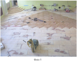
Фото 1. Сверление крепежных отверстий в монтажных листах. Одновременно со сверлением выполняют зенкование отверстий. Для этого на сверле установлен зенкер, что хорошо видно на фотографии.
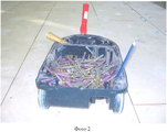
Фото 2. Укладка монтажных листов. На переднем плане контейнер с элементами крепления «саморез + дюбель». В правой верхней части видны установленные, но еще не завинченные саморезы.
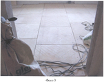
Фото 3. Выявление недопустимых неровностей на поверхности фанерного основания. На фотографии хорошо видны группы рельефных индикаторных отрезков линий, которые обозначают области недопустимых неровностей для последующего удаления.
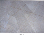
Фото 4. Выявление недопустимых неровностей на поверхности паркетного покрытия. Рельефные индикаторные отрезки линий обозначают области недопустимых неровностей для последующего удаления.
Фото 5. Укладка паркетных элементов в паркетное покрытие на чистовом фанерном основании. На переднем плане хорошо видны темные и светлые с темным ореолом пятна, которые образованы на месте нахождения недопустимых неровностей, после их удаления. Темные пятна соответствуют удалению одного слоя фанеры, а светлые пятна внутри темных соответствуют удалению двух слоев фанеры.
Claims (1)
Priority Applications (1)
| Application Number | Priority Date | Filing Date | Title |
|---|---|---|---|
| RU2010105131/03A RU2425198C2 (en) | 2010-02-15 | 2010-02-15 | Method of making parquet floors |
Applications Claiming Priority (1)
| Application Number | Priority Date | Filing Date | Title |
|---|---|---|---|
| RU2010105131/03A RU2425198C2 (en) | 2010-02-15 | 2010-02-15 | Method of making parquet floors |
Publications (2)
| Publication Number | Publication Date |
|---|---|
| RU2010105131A RU2010105131A (en) | 2011-02-27 |
| RU2425198C2 true RU2425198C2 (en) | 2011-07-27 |
Family
ID=44753727
Family Applications (1)
| Application Number | Title | Priority Date | Filing Date |
|---|---|---|---|
| RU2010105131/03A RU2425198C2 (en) | 2010-02-15 | 2010-02-15 | Method of making parquet floors |
Country Status (1)
| Country | Link |
|---|---|
| RU (1) | RU2425198C2 (en) |
Cited By (1)
| Publication number | Priority date | Publication date | Assignee | Title |
|---|---|---|---|---|
| RU2564039C2 (en) * | 2013-12-11 | 2015-09-27 | Касаткин Алексей Леонидович | Laying method of installation veneer sheets under parquet flooring |
Citations (3)
| Publication number | Priority date | Publication date | Assignee | Title |
|---|---|---|---|---|
| EP1371465A2 (en) * | 2002-06-11 | 2003-12-17 | Franz Storek | Ready to use parquet flooring |
| RU70277U1 (en) * | 2007-07-05 | 2008-01-20 | Леонид Иванович Фатеев | ADJUSTABLE FLOOR |
| RU73898U1 (en) * | 2007-03-06 | 2008-06-10 | Виталий Викторович Гуров | FLOOR |
-
2010
- 2010-02-15 RU RU2010105131/03A patent/RU2425198C2/en not_active IP Right Cessation
Patent Citations (3)
| Publication number | Priority date | Publication date | Assignee | Title |
|---|---|---|---|---|
| EP1371465A2 (en) * | 2002-06-11 | 2003-12-17 | Franz Storek | Ready to use parquet flooring |
| RU73898U1 (en) * | 2007-03-06 | 2008-06-10 | Виталий Викторович Гуров | FLOOR |
| RU70277U1 (en) * | 2007-07-05 | 2008-01-20 | Леонид Иванович Фатеев | ADJUSTABLE FLOOR |
Non-Patent Citations (1)
| Title |
|---|
| АЛИНИН Б.К. Паркетные полы. - М.: ООО Аделант, 2000, с.91-92. * |
Cited By (1)
| Publication number | Priority date | Publication date | Assignee | Title |
|---|---|---|---|---|
| RU2564039C2 (en) * | 2013-12-11 | 2015-09-27 | Касаткин Алексей Леонидович | Laying method of installation veneer sheets under parquet flooring |
Also Published As
| Publication number | Publication date |
|---|---|
| RU2010105131A (en) | 2011-02-27 |
Similar Documents
| Publication | Publication Date | Title |
|---|---|---|
| US7971327B2 (en) | Process and system for sub-dividing a laminated flooring substrate | |
| EP1264053B1 (en) | Surface groove system for building sheets | |
| US8186399B2 (en) | Automated floor board texturing cell and method | |
| US2021457A (en) | Stair carriage | |
| BRPI0515836B1 (en) | METHOD FOR COATING A SURFACE | |
| US20240360680A1 (en) | Method for composing a set of floor panels | |
| US20060144011A1 (en) | Tile spacer | |
| CA2750731C (en) | Manufacturing of tongue and groove profiles on hardwood floorboards | |
| EP2517834A3 (en) | Fastener, installation tool and related method of use | |
| US20130326989A1 (en) | Wooden Floor Tile With Milled Surface | |
| CN103375016A (en) | Dry flooring structure | |
| CN117145178B (en) | A construction method for irregularly shaped indoor wall slabs | |
| US20210246666A1 (en) | Systems and Methods Related to Natural Wood Products | |
| US9102078B2 (en) | Cutting method for stone laminate panels | |
| RU2010105131A (en) | METHOD FOR CREATING PARQUET FLOORS | |
| CN104343220B (en) | A kind of trim components, decoration board mounting structure and its mounting process | |
| US2348724A (en) | Flooring | |
| JP2019085722A (en) | Finish surface material cutting position marking tool and construction method of finish surface material using it | |
| RU221570U1 (en) | ENGINEERING BASE FOR FINAL FLOORING COVERINGS | |
| US20260132636A1 (en) | Method for composing a set of floor panels | |
| CN204658584U (en) | Platform bores adjusts chi template | |
| US9567761B1 (en) | Cutting fence with handle | |
| US8196881B1 (en) | Countertop cut-out retainer and method of use thereof | |
| Manual | 2008 | |
| AU774540B2 (en) | Wall lining system |
Legal Events
| Date | Code | Title | Description |
|---|---|---|---|
| MM4A | The patent is invalid due to non-payment of fees |
Effective date: 20120216 |