RU2425200C1 - Guard based on spiral barrier - Google Patents
Guard based on spiral barrier Download PDFInfo
- Publication number
- RU2425200C1 RU2425200C1 RU2010102986/03A RU2010102986A RU2425200C1 RU 2425200 C1 RU2425200 C1 RU 2425200C1 RU 2010102986/03 A RU2010102986/03 A RU 2010102986/03A RU 2010102986 A RU2010102986 A RU 2010102986A RU 2425200 C1 RU2425200 C1 RU 2425200C1
- Authority
- RU
- Russia
- Prior art keywords
- spiral
- spirals
- equator
- relative
- fence
- Prior art date
Links
Images

Landscapes
- Burglar Alarm Systems (AREA)
- Fencing (AREA)
Abstract
Description
Изобретение относится к техническим средствам охраны и может быть использовано для физической защиты и сигнализационного блокирования периметров объектов и протяженных рубежей на равниной и пересеченной местности.The invention relates to technical means of protection and can be used for physical protection and signaling blocking of the perimeters of objects and long lines on a plain and rough terrain.
Известны технические средства охраны периметров объектов - средства обнаружения, основанные на разных физических принципах действия (вибрационные, трибоэлектрические, емкостные, оптоволоконные), содержащие заграждение (сетчатое, решетчатое, кирпичное, железобетонное и др.), являющееся физическим барьером, создающим задержку несанкционированному проникновению на территорию объекта. Для обеспечения сигнализационного блокирования чувствительные элементы данных средств обнаружения размещаются на заграждении.Known technical means of protecting the perimeters of objects - detection tools based on different physical principles of operation (vibration, triboelectric, capacitive, fiber), containing a barrier (mesh, trellis, brick, reinforced concrete, etc.), which is a physical barrier that creates a delay in unauthorized entry to the territory of the facility. To ensure signaling blocking, sensitive elements of these detection tools are placed on the fence.
Известно охранное заграждение по патенту РФ 2268977, предназначенное для защиты объектов от несанкционированного проникновения. Охранное заграждение включает винтовой спиральный зазубренный элемент. Этот элемент установлен по периметру охранной зоны на ее границе, причем в него ведены шаровые блоки. Шаровые блоки выполнены из кольцевых зазубренных элементов, расположенных на равном угловом расстоянии вокруг общей оси с образованием шаровидного тела взаимной фиксацией кольцевых зазубренных элементов в полюсах этого шаровидного тела. В каждый шаровой блок введен дополнительный кольцевой зазубренный элемент, установленный по экватору упомянутого шаровидного тела. Недостатком данного охранного заграждения является отсутствие в его составе средства обнаружения, обеспечивающего сигнализационное блокирование периметра охранной зоны при попытке преодоления заграждения нарушителем.Known security fence according to the patent of Russian Federation 2268977, designed to protect objects from unauthorized entry. The security fence includes a helical spiral notched element. This element is installed around the perimeter of the security zone at its border, and ball blocks are led into it. Spherical blocks are made of annular serrated elements located at an equal angular distance around a common axis with the formation of a spherical body by mutual fixation of the annular serrated elements in the poles of this spherical body. An additional annular serrated element is installed in each ball block, which is installed along the equator of the said spherical body. The disadvantage of this security fence is the lack of detection means in its composition, which provides an alarm blocking of the perimeter of the security zone when an intruder tries to overcome the barrier.
Известно заграждение по патенту РФ 2315159 на основе спиральных элементов, предназначенное для установки и демонтажа в короткие сроки непреодолимых заграждений для организации временных и длительно охраняемых территорий. Блок спиралей для мобильного заграждения содержит три спирали одинакового диаметра из колючей ленты, ориентированные относительно друг друга в форме треугольной призмы, причем все витки соседних спиралей попарно соединены между собой в точках их соприкосновения, равномерно распределенных по окружности витка и расположенных на одной прямой по длине спирали. Недостатком данного заграждения является отсутствие в его составе средства обнаружения, обеспечивающего сигнализационное блокирование периметра охраняемой территории при попытке преодоления заграждения нарушителем.Known barrier according to the patent of the Russian Federation 2315159 based on spiral elements, designed for installation and dismantling in a short time insurmountable barriers for the organization of temporary and long-term protected areas. A block of spirals for a mobile fence contains three spirals of the same diameter from barbed tape, oriented relative to each other in the form of a triangular prism, with all turns of adjacent spirals pairwise interconnected at points of contact uniformly distributed around the circumference of the coil and located on one straight line along the length of the spiral . The disadvantage of this obstacle is the lack of a means of detection in its composition, which provides signaling blocking of the perimeter of the protected area when trying to overcome the obstacle by an intruder.
Известно комбинированное средство охраны периметров объектов (см. свидетельство на полезную модель РФ 66835), предназначенное для построения протяженных, замкнутых рубежей охраны периметров объектов. Данное средство представляет собой сигнализационное заграждение, выполненное в виде однорядного решетчатого забора на металлических несущих стойках и установленного на нем комбинированного средства обнаружения нарушителя. Комбинированное средство охраны оснащено с внешней стороны предупредительным заграждением в виде однорядного сетчатого забора на металлических несущих стойках, установленных в грунте, а с внутренней стороны - инженерным заградительным препятствием в виде однорядного сетчатого забора с козырьком на металлических стойках, установленных в грунте, снабженного четырьмя рядами спирального барьера безопасности из армированной колючей ленты. Недостатком данного комбинированного средства охраны является высокая стоимость оборудования и большая трудоемкость монтажа средства на месте эксплуатации.A combined means of protecting the perimeters of objects is known (see certificate for a utility model of the Russian Federation 66835), intended for constructing extended, closed lines of protection for perimeters of objects. This tool is an alarm fence made in the form of a single-row trellised fence on metal load-bearing racks and a combined means of detecting an intruder installed on it. The combined security equipment is equipped on the outside with a warning fence in the form of a single-row mesh fence on metal support racks installed in the ground, and on the inside, with an engineering obstacle in the form of a single-row mesh fence with a visor on metal racks installed in the ground, equipped with four rows of spiral safety barriers made of reinforced barbed tape. The disadvantage of this combined means of protection is the high cost of equipment and the high complexity of installing the tool on site.
В основу настоящего изобретения положена техническая задача уменьшения стоимости оборудования и сокращения трудоемкости монтажа путем создания охранного устройства на основе спирального заграждения, обеспечивающего сигнализационное блокирование периметра охраняемой территории при попытке преодоления заграждения нарушителем.The present invention is based on the technical task of reducing the cost of equipment and reducing the complexity of installation by creating a security device based on a spiral fence, providing an alarm blocking the perimeter of the protected area when trying to overcome the barrier by the intruder.
Указанная техническая задача решена за счет того, что предложенное охранное устройство на основе спирального заграждения, содержащее три спирали одинакового диаметра из колючей ленты, армированной проволочным сердечником, ориентированные относительно друг друга в форме треугольной призмы таким образом, что две нижние спирали составляют основание, а третья верхняя спираль - вершину призмы, причем все витки соседних спиралей попарно соединены между собой в точках их соприкосновения, расположенных на одной прямой по длине спирали, согласно настоящему изобретению содержит вибрационное средство обнаружения, имеющее два кабельных чувствительных элемента, нижний и верхний, при этом нижний чувствительный элемент закрепляется на одной из нижних спиралей по ее длине и с угловым расстоянием φ1 от 0° до 90° относительно экватора, а верхний чувствительный элемент закрепляется на верхней спирали параллельно нижнему чувствительному элементу и с угловым расстоянием φ2 от 0° до 90° относительно экватора этой спирали, при этом под экватором спирали понимается горизонтальная плоскость, проходящая через центр витка спирали.This technical problem is solved due to the fact that the proposed security device based on a spiral fence, containing three spirals of the same diameter from a barbed tape reinforced with a wire core, oriented relative to each other in the form of a triangular prism so that the two lower spirals form the base and the third the upper spiral is the top of the prism, and all the turns of adjacent spirals are paired together at points of contact located on one straight line along the length of the spiral, according to but the present invention comprises a vibration detecting means having two cable-sensitive element, the bottom and upper, the lower sensitive element is fixed on one of the lower spirals along its length and with an angular spacing φ 1 from 0 ° to 90 ° relative to the equator, and the upper sensor the element is fixed on the upper spiral parallel to the lower sensitive element and with an angular distance φ 2 from 0 ° to 90 ° relative to the equator of this spiral, while the equator of the spiral refers to the horizontal plane b passing through the center of the spiral loop.
Сущность изобретения поясняется фиг.1-2.The invention is illustrated figure 1-2.
На фиг.1 показан эскиз одного из возможных вариантов конструктивного исполнения охранного устройства на основе спирального заграждения. Здесь показаны виды: спереди а), сверху б), сбоку в) и сбоку в перспективной проекции г).Figure 1 shows a sketch of one of the possible options for the design of a security device based on a spiral fence. The views are shown here: front a), top b), side c) and side in perspective projection d).
На фиг.2 показан общий вид с внешней по отношению к охраняемой территории стороны одного из возможных вариантов конструктивного исполнения основных элементов охранного устройства на основе спирального заграждения.Figure 2 shows a General view from the outside with respect to the protected area of the side of one of the possible options for the design of the main elements of the security device based on a spiral fence.
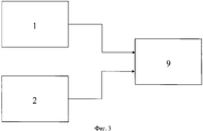
На фиг.3 показана структурная схема вибрационного средства обнаружения.Figure 3 shows a structural diagram of a vibration detection means.
На фиг.1-3 использованы следующие обозначения:1-3, the following notation is used:
1 - нижний кабельный чувствительный элемент; 2 - верхний кабельный чувствительный элемент; 3 и 4 - нижние спирали заграждения; 5 - верхняя спираль заграждения; 6 - зазубренная колючая лента; 7 - проволочный сердечник колючей ленты; 8 - стяжка крепления кабельного чувствительного элемента к спирали; 9 - электронный блок обработки вибрационного средства обнаружения.1 - lower cable sensing element; 2 - upper cable sensing element; 3 and 4 - lower spiral barriers; 5 - upper spiral boom; 6 - barbed barbed tape; 7 - wire core of barbed tape; 8 - coupler mounting cable sensing element to the spiral; 9 - electronic processing unit of the vibration detection means.
Однотипные узлы обозначены на чертежах одинаковыми позициями.Uniform nodes are indicated in the drawings by the same reference numbers.
Устройство состоит из взаимосвязанных узлов, соединенных электрически по правилам, известным в данной области техники. По периметру охраняемой территории устанавливается спиральное заграждение, состоящее из трех спиралей одинакового диаметра: двух нижних 3 и 4 и одной верхней 5. Спирали 3, 4 и 5 ориентированы относительно друг друга в форме треугольной призмы, причем все витки соседних спиралей попарно соединены между собой в точках их соприкосновения, расположенных на одной прямой по длине спирали. После установки спиральное заграждение фиксируется на земле для обеспечения его устойчивого расположения на периметре охраняемой территории.The device consists of interconnected nodes connected electrically according to the rules known in the art. A spiral fence consisting of three spirals of the same diameter is installed along the perimeter of the protected area: two lower 3 and 4 and one upper 5.
Каждая спираль выполнена из холоднокатаной стальной проволоки (проволочного сердечника 7), на которой закреплена путем обжатия зазубренная колючая лента 6. Армирование спиралей 3, 4 и 5 проволочным сердечником позволяет обеспечить стабильный шаг скрутки спирали с повышенной степенью жесткости, что повышает эксплуатационную надежность спирального заграждения. Благодаря значительному режущему эффекту и пружинящим свойствам спиральное заграждение представляет собой особо труднопреодолимое физическое препятствие вследствие своей объемной конструкции.Each spiral is made of cold-rolled steel wire (wire core 7), on which a barbed barbed tape is fixed by crimping 6. Reinforcing
Вибрационное средство обнаружения состоит из кабельных чувствительных элементов 1 и 2 и электронного блока обработки 9.Vibration detection means consists of
Конструктивно блок обработки 9 выполнен на базе унифицированного металлического корпуса в виде съемного блока с кронштейном, с помощью которого он устанавливается, например, внутри шкафа участкового для защиты от атмосферных воздействий и механических повреждений. Внутри корпуса блока обработки 9 расположены: зарядочувствительный усилитель, фильтры, процессор и исполнительное устройство на основе твердотельного реле.Structurally, the
Кабельные чувствительные элементы 1 и 2 выполнены на основе специальных трибоэлектрических кабелей, восприимчивых к вибрации. Они крепятся на заграждении к виткам спиралей с помощью светоустойчивых пластиковых стяжек 8. Установка осуществляется на внешней по отношению к охраняемой территории стороне заграждения. Кабельный чувствительный элемент 1 крепится к нижней спирали 3 параллельно поверхности земли на уровне центра витка спирали или выше, при этом его угловое расстояние φ1 (см. Фиг.1в) относительно горизонтальной плоскости, проходящей через центр витка спирали, должно быть выбрано из интервала от 0° до 90°. Кабельный чувствительный элемент 2 крепится к верхней спирали 5 параллельно кабельному чувствительному элементу 1 на уровне центра витка спирали или выше, при этом его угловое расстояние φ2 (см. Фиг.1в) относительно горизонтальной плоскости, проходящей через центр витка спирали, также должно быть выбрано из интервала от 0° до 90°. Такая установка чувствительных элементов 1 и 2 позволяет повысить помехоустойчивость средства обнаружения за счет вычитания синфазных помех на входе блока обработки 9.Cable
Охранное устройство на основе спирального заграждения работает следующим образом.Security device based on a spiral fence works as follows.
Проводят подготовку устройства к эксплуатации. Осуществляют внешний осмотр оборудования на предмет правильности монтажа и надежности подключения электрических цепей при выключенном электропитании. Подают электропитание на блок обработки 9, производят контроль исправности оборудования, подключают блок обработки 9 к системе сбора и обработки информации и организуют круглосуточное дежурство сменных операторов за пультом управления.Prepare the device for operation. Carry out an external inspection of the equipment for proper installation and reliability of electrical circuits when the power is off. They supply power to the
Функционирование охранного устройства основано на образовании вибрационным средством обнаружения зоны обнаружения на спиральном заграждении, при пересечении которой нарушителем или группой нарушителей в систему сбора и обработки информации выдается сигнал срабатывания.The operation of the security device is based on the formation of a detection zone on a spiral fence with a vibrating means of detection, at the intersection of which an intruder or a group of intruders transmits a response signal to the information collection and processing system.
При попытке перелаза через спиральное заграждение и деформации или разрушении спиралей нарушителем деформация и вибрации спиралей 3 и 5 передаются кабельным чувствительным элементам 1 и 2 вибрационного средства обнаружения. Деформация и вибрации кабельных чувствительных элементов 1 и 2 вызывают появление электрических сигналов (вследствие трибоэлектрического эффекта) на их выходах. Электрические сигналы с кабельных чувствительных элементов 1 и 2 поступают в блок обработки 9, усиливаются, фильтруются и обрабатываются таким образом, чтобы в соответствии с отличительными признаками выделить сигналы, инициированные воздействием нарушителя на спиральное заграждение. Блок обработки 9 выдает сигнал срабатывания в виде размыкания нормально замкнутых контактов реле, который поступает для дальнейшего анализа в систему сбора и обработки информации.When attempting to climb over a spiral barrier and deform or destroy the spirals by the intruder, the deformation and vibration of the
Заявляемое охранное устройство позволяет обеспечить надежную охрану объекта от проникновения нарушителя. При попытке преодоления спирального заграждения нарушитель подвергается опасности получения травмы при контакте с зазубренными элементами колючей ленты. При попытке раздвинуть витки или разрушить спирали произойдет срабатывание вибрационного средства обнаружения. При попытке преодолеть охранную полосу, используя плотный материал для накрытия спиралей заграждения, также произойдет срабатывание вибрационного средства обнаружения.The inventive security device allows you to provide reliable protection of the object from the intruder. When trying to overcome a spiral fence, the intruder is in danger of getting injured in contact with the barbed tape barbed elements. If you try to push the turns or break the spirals, the vibration detection means will trigger. If you try to overcome the guard strip using dense material to cover the spirals of the fence, the vibration detection means will also trigger.
По сравнению с традиционными охранными устройствами заградительного типа заявляемое техническое решение обладает рядом существенных преимуществ, а именно:Compared with traditional security devices of the barrage type, the claimed technical solution has a number of significant advantages, namely:
- отсутствие необходимости сооружения опорных конструкций в виде столбов и заборов, требующих проведения земляных работ, что значительно повышает стоимость установки заграждения;- the absence of the need for the construction of supporting structures in the form of pillars and fences, requiring excavation, which significantly increases the cost of installing the fence;
- установка спирального заграждения в кратчайшие сроки;- installation of a spiral fence in the shortest possible time;
- малочисленность обслуживающего персонала (2-3 человека);- the small number of staff (2-3 people);
- благодаря высокой просматриваемости спиральное заграждение позволяет осуществлять как визуальный, так и телевизионный контроль территорий как внутри заграждения, так и с его наружной стороны.- due to its high visibility, the spiral fence allows both visual and television control of the territories both inside the fence and from its outside.
Claims (1)
Priority Applications (2)
| Application Number | Priority Date | Filing Date | Title |
|---|---|---|---|
| RU2010102986/03A RU2425200C1 (en) | 2010-02-01 | 2010-02-01 | Guard based on spiral barrier |
| EA201000778A EA017788B1 (en) | 2010-02-01 | 2010-06-09 | Guarding device based on spiral barrier |
Applications Claiming Priority (1)
| Application Number | Priority Date | Filing Date | Title |
|---|---|---|---|
| RU2010102986/03A RU2425200C1 (en) | 2010-02-01 | 2010-02-01 | Guard based on spiral barrier |
Publications (1)
| Publication Number | Publication Date |
|---|---|
| RU2425200C1 true RU2425200C1 (en) | 2011-07-27 |
Family
ID=44544183
Family Applications (1)
| Application Number | Title | Priority Date | Filing Date |
|---|---|---|---|
| RU2010102986/03A RU2425200C1 (en) | 2010-02-01 | 2010-02-01 | Guard based on spiral barrier |
Country Status (2)
| Country | Link |
|---|---|
| EA (1) | EA017788B1 (en) |
| RU (1) | RU2425200C1 (en) |
Cited By (2)
| Publication number | Priority date | Publication date | Assignee | Title |
|---|---|---|---|---|
| RU2651745C1 (en) * | 2017-04-11 | 2018-04-23 | Юрий Александрович Русанов | Security device on the basis of spiral fence |
| RU183633U1 (en) * | 2017-09-18 | 2018-09-28 | Федеральное Государственное Казенное Военное Образовательное Учреждение Высшего Образования Военный Учебно-Научный Центр Сухопутных Войск "Общевойсковая Академия Вооруженных Сил Российской Федерации" | Remote-mounted alarm-electrified boom |
Families Citing this family (1)
| Publication number | Priority date | Publication date | Assignee | Title |
|---|---|---|---|---|
| RU194101U1 (en) * | 2019-10-11 | 2019-11-28 | Акционерное общество "Научно-производственный комплекс "Дедал" | Lifting device for mounting barbed tape on a solid fence |
Citations (5)
| Publication number | Priority date | Publication date | Assignee | Title |
|---|---|---|---|---|
| CA712411A (en) * | 1965-06-29 | Kirsch Karl | Device for laying down a barbed wire barricade | |
| GB2175028A (en) * | 1985-03-25 | 1986-11-19 | Cochrane Steel Prod Pty Ltd | Coiled tape or wire barrier |
| RU2268977C2 (en) * | 2002-09-18 | 2006-01-27 | Общество с Ограниченной Ответственностью (ООО) "АГ Инжиниринг" | Protective fence block and protective fence |
| RU66835U1 (en) * | 2007-06-01 | 2007-09-27 | Федеральное государственное унитарное предприятие "Дедал" | COMBINED MEANS OF PROTECTING PERIMETERS OF OBJECTS |
| RU2315159C1 (en) * | 2006-06-13 | 2008-01-20 | Общество с ограниченной ответственностью "Атлант-Медиа" | Spiral block for movable barrier |
Family Cites Families (1)
| Publication number | Priority date | Publication date | Assignee | Title |
|---|---|---|---|---|
| RU2262575C2 (en) * | 2003-07-01 | 2005-10-20 | Государственное учреждение Научно-производственное объединение "Специальная техника и связь" Министерства внутренних дел Российской Федерации | Spiral unit for movable barrier and vehicle to deliver and deploy thereof |
-
2010
- 2010-02-01 RU RU2010102986/03A patent/RU2425200C1/en active IP Right Revival
- 2010-06-09 EA EA201000778A patent/EA017788B1/en not_active IP Right Cessation
Patent Citations (5)
| Publication number | Priority date | Publication date | Assignee | Title |
|---|---|---|---|---|
| CA712411A (en) * | 1965-06-29 | Kirsch Karl | Device for laying down a barbed wire barricade | |
| GB2175028A (en) * | 1985-03-25 | 1986-11-19 | Cochrane Steel Prod Pty Ltd | Coiled tape or wire barrier |
| RU2268977C2 (en) * | 2002-09-18 | 2006-01-27 | Общество с Ограниченной Ответственностью (ООО) "АГ Инжиниринг" | Protective fence block and protective fence |
| RU2315159C1 (en) * | 2006-06-13 | 2008-01-20 | Общество с ограниченной ответственностью "Атлант-Медиа" | Spiral block for movable barrier |
| RU66835U1 (en) * | 2007-06-01 | 2007-09-27 | Федеральное государственное унитарное предприятие "Дедал" | COMBINED MEANS OF PROTECTING PERIMETERS OF OBJECTS |
Cited By (3)
| Publication number | Priority date | Publication date | Assignee | Title |
|---|---|---|---|---|
| RU2651745C1 (en) * | 2017-04-11 | 2018-04-23 | Юрий Александрович Русанов | Security device on the basis of spiral fence |
| EA031532B1 (en) * | 2017-04-11 | 2019-01-31 | Юрий Александрович Русанов | Safeguard device based on a spiral barrier |
| RU183633U1 (en) * | 2017-09-18 | 2018-09-28 | Федеральное Государственное Казенное Военное Образовательное Учреждение Высшего Образования Военный Учебно-Научный Центр Сухопутных Войск "Общевойсковая Академия Вооруженных Сил Российской Федерации" | Remote-mounted alarm-electrified boom |
Also Published As
| Publication number | Publication date |
|---|---|
| EA017788B1 (en) | 2013-03-29 |
| EA201000778A1 (en) | 2011-08-30 |
Similar Documents
| Publication | Publication Date | Title |
|---|---|---|
| KR101287079B1 (en) | Intrusion position detecting system using 3d sensor | |
| US20090008619A1 (en) | Security fence module | |
| RU2599527C1 (en) | Method for combined protection of perimeter of extended object | |
| CN107424369A (en) | A kind of optic cable vibration sensor alarm of low rate of false alarm | |
| RU2425200C1 (en) | Guard based on spiral barrier | |
| RU2599523C1 (en) | Method for combined protection of perimeter of extended object | |
| CN103883159B (en) | Enclose boundary's securing system | |
| DE69942616D1 (en) | INTRODUCTION FENCE WITH TRIGGER WIRE AND A COMMON ACTUATOR | |
| CN102289904A (en) | Intrusion detection method and system | |
| CN206991492U (en) | A kind of optic cable vibration sensor alarm of low rate of false alarm | |
| RU66835U1 (en) | COMBINED MEANS OF PROTECTING PERIMETERS OF OBJECTS | |
| RU96274U1 (en) | COMPLEX OF PROTECTION OF LONG SITES OF SINGLE-RAILED RAILWAY | |
| RU93434U1 (en) | COMBINED LATERATED ALARMS | |
| RU68157U1 (en) | COMBINED MEANS OF PROTECTING PERIMETERS OF OBJECTS | |
| CN204024200U (en) | Enclose boundary's protection system | |
| JP4218501B2 (en) | Security device | |
| JP5609279B2 (en) | Barrier system | |
| RU132470U1 (en) | FITTING PIPE WITH AN EXTRA SAFETY BARRIER | |
| JP3018244U (en) | Concrete guard fence | |
| RU120992U1 (en) | PIRANIA T SERIES ENGINEERING BARRIER | |
| KR102428514B1 (en) | Metal sensing device and system for preventing crime and diasasters using thereof | |
| RU164841U1 (en) | VIBRATION DETECTION SYSTEM WITH HIDDEN INSTALLATION OF SENSITIVE ELEMENT | |
| CN213781143U (en) | Perimeter anti-crossing system with intelligent access control | |
| JP5356050B2 (en) | Security system for subdivisions | |
| CN215331894U (en) | A vibrations steel pipe early warning rail for border |
Legal Events
| Date | Code | Title | Description |
|---|---|---|---|
| MM4A | The patent is invalid due to non-payment of fees |
Effective date: 20130202 |
|
| NF4A | Reinstatement of patent |
Effective date: 20140420 |