RU2425202C2 - Pad - Google Patents
Pad Download PDFInfo
- Publication number
- RU2425202C2 RU2425202C2 RU2007135204/12A RU2007135204A RU2425202C2 RU 2425202 C2 RU2425202 C2 RU 2425202C2 RU 2007135204/12 A RU2007135204/12 A RU 2007135204/12A RU 2007135204 A RU2007135204 A RU 2007135204A RU 2425202 C2 RU2425202 C2 RU 2425202C2
- Authority
- RU
- Russia
- Prior art keywords
- recess
- pad
- cover
- lining
- hole made
- Prior art date
Links
- 238000009434 installation Methods 0.000 claims description 7
- 230000037431 insertion Effects 0.000 claims description 4
- 238000003780 insertion Methods 0.000 claims description 4
- 238000010276 construction Methods 0.000 abstract 1
- 239000000126 substance Substances 0.000 abstract 1
- 230000001681 protective effect Effects 0.000 description 2
- 230000015572 biosynthetic process Effects 0.000 description 1
Images


Classifications
-
- E—FIXED CONSTRUCTIONS
- E05—LOCKS; KEYS; WINDOW OR DOOR FITTINGS; SAFES
- E05B—LOCKS; ACCESSORIES THEREFOR; HANDCUFFS
- E05B15/00—Other details of locks; Parts for engagement by bolts of fastening devices
- E05B15/02—Striking-plates; Keepers; Bolt staples; Escutcheons
-
- E—FIXED CONSTRUCTIONS
- E05—LOCKS; KEYS; WINDOW OR DOOR FITTINGS; SAFES
- E05B—LOCKS; ACCESSORIES THEREFOR; HANDCUFFS
- E05B17/00—Accessories in connection with locks
- E05B17/0054—Fraction or shear lines; Slip-clutches, resilient parts or the like for preventing damage when forced or slammed
- E05B17/0062—Fraction or shear lines; Slip-clutches, resilient parts or the like for preventing damage when forced or slammed with destructive disengagement
-
- E—FIXED CONSTRUCTIONS
- E05—LOCKS; KEYS; WINDOW OR DOOR FITTINGS; SAFES
- E05B—LOCKS; ACCESSORIES THEREFOR; HANDCUFFS
- E05B17/00—Accessories in connection with locks
- E05B17/20—Means independent of the locking mechanism for preventing unauthorised opening, e.g. for securing the bolt in the fastening position
-
- E—FIXED CONSTRUCTIONS
- E05—LOCKS; KEYS; WINDOW OR DOOR FITTINGS; SAFES
- E05B—LOCKS; ACCESSORIES THEREFOR; HANDCUFFS
- E05B3/00—Fastening knobs or handles to lock or latch parts
- E05B3/06—Fastening knobs or handles to lock or latch parts by means arranged in or on the rose or escutcheon
Landscapes
- Engineering & Computer Science (AREA)
- Mechanical Engineering (AREA)
- Casings For Electric Apparatus (AREA)
- Laminated Bodies (AREA)
- Auxiliary Devices For Machine Tools (AREA)
- Polishing Bodies And Polishing Tools (AREA)
- Electromechanical Clocks (AREA)
- Vehicle Interior And Exterior Ornaments, Soundproofing, And Insulation (AREA)
- Air Bags (AREA)
- Connection Of Plates (AREA)
- Lock And Its Accessories (AREA)
- Stringed Musical Instruments (AREA)
Abstract
Description
Область техникиTechnical field
Настоящее изобретение относится к накладкам, применяемым для замков на дверях, люках и т.д. Накладки могут быть соединены с поворотными ручками, ручками-скобами, ручками-кнопками, другими комплектующими деталями замка или с корпусом цилиндра.The present invention relates to linings used for locks on doors, hatches, etc. Pads can be connected to rotary handles, handle-brackets, handle-buttons, other components of the lock or to the cylinder body.
Предшествующий уровень техникиState of the art
Накладки применяются для замков на дверях, люках и т.д., чтобы закрыть отверстия, проделанные механическим способом, в установочном основании, например, дверь. В некоторых случаях установочные накладки применяются для того, чтобы прикрепить комплектующие детали замка. Отверстия, проделанные механическим способом, требуются для комплектующих деталей замка и корпуса цилиндра. Другими словами, отверстия, проделанные механическим способом, требуются, чтобы вставить замок. Обычные комплектующие детали замка включают поворотную ручку, ручку-кнопку и ручку-скобу. Отверстие, проделанное механическим способом, часто проходит через толщину двери, образуя отверстия с обеих сторон двери. Когда имеются в наличии накладки на противоположных сторонах двери, чтобы закрыть отверстие, проделанное механическим способом, обычный способ заключается в том, чтобы прикрепить накладки друг к другу, используя сквозные винты или сквозные болты, которые прижимают накладки к двери. Соединительные детали - то есть сквозные винты или сквозные болты - расположены так, чтобы пройти через отверстия в корпусе замка через дверь.Pads are used for locks on doors, hatches, etc., to close the holes made mechanically in the installation base, for example, a door. In some cases, the mounting pads are used to attach the components of the lock. Holes made mechanically are required for the components of the lock and cylinder body. In other words, holes made mechanically are required to insert a lock. Common accessories for a lock include a rotary knob, a knob, and a knob. A hole made mechanically often passes through the thickness of the door, forming holes on both sides of the door. When pads on opposite sides of the door are available to close a hole made mechanically, the usual way is to attach pads to each other using through screws or through bolts that press the pads against the door. Connecting parts — that is, through screws or through bolts — are positioned to pass through openings in the lock body through the door.
Если намерение заключается в том, чтобы плотно установить ручку со шпинделем в отверстие, сделанное в накладке для шпинделя, накладку часто называют накладкой для ручки. С другой стороны, если накладка предназначена для установки с корпусом цилиндра, ее часто называют накладкой корпуса цилиндра или защитным кольцом. Накладка без отверстия для ручки, корпуса цилиндра или другого компонента обычно используется, чтобы закрыть отверстие, проделанное механическим способом, на противоположной стороне двери. Накладка может также быть сконструирована для установки ручки-кнопки, тогда ее называют накладкой ручки-кнопки. Таким образом накладка в общем относится ко всем типам накладок, которые закрывают отверстие, проделанное механическим способом в установочном основании.If the intention is to fit the handle with the spindle firmly into the hole made in the spindle cover, the cover is often called the handle cover. On the other hand, if a cover is intended to be installed with a cylinder body, it is often called a cylinder body cover or protective ring. A cover plate without a hole for a handle, cylinder body or other component is usually used to close a hole made mechanically on the opposite side of the door. The overlay can also be designed to install a button-handle, then it is called the button-handle overlay. Thus, the pad generally applies to all types of linings that close a hole made mechanically in the mounting base.
Назначение накладок состоит в том, чтобы защитить корпус замка и шпиндель внутри двери от внешнего загрязнения и вандализма. Накладка является также эстетически более привлекательной, чем открытое отверстие, проделанное механическим способом. Особенно для входных дверей накладка должна иметь защитный эффект против взлома. Особенностей защиты накладок от взлома уже довольно много, но они должны быть еще улучшены для особых требований установки.The purpose of the linings is to protect the lock body and the spindle inside the door from external pollution and vandalism. The cover is also aesthetically more attractive than an open hole made mechanically. Especially for entrance doors, the overlay should have a protective effect against breaking. There are already quite a lot of features for protecting linings from breaking, but they should be further improved for special installation requirements.
Краткое описание изобретенияSUMMARY OF THE INVENTION
Цель изобретения состоит в том, чтобы улучшить особенности защиты накладок от взлома. Цель будет достигнута с помощью изобретения, как описано в п.1 формулы изобретения. Другие пункты формулы изобретения описывают различные варианты осуществления изобретения.The purpose of the invention is to improve the security features of the pads against breaking. The objective will be achieved by the invention, as described in
Накладка 1 по изобретению содержит углубление 5, 8, 9, расположенное на установочной поверхности накладки, которая предназначена, чтобы быть плотно прижатой к установочному основанию. Углубление образует контур так, что он окружает отверстие, проделанное механическим способом, когда накладка смонтирована на установочном основании. Между дном углубления 5, 8, 9 и передней поверхностью накладки находится шейка из материала 7. Если предпринята попытка отжать накладку от установочного основания, вставляя инструмент типа долота или лома между установочным основанием и краем накладки, шейка из материала между дном углубления и накладкой погнется, сделав внешний край накладки отделенным от остальной части конструкции накладки. Оставшаяся часть конструкции накладки не обеспечивает никакой хорошей опорной поверхности для инструментов взломщиков.The
Список чертежейDrawing list
Далее изобретение описано более подробно со ссылкой на приложенные чертежи, на которыхThe invention will now be described in more detail with reference to the attached drawings, in which
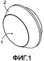
Фиг.1 иллюстрирует пример накладки, вид со стороны передней поверхности.Figure 1 illustrates an example of a lining, a view from the front surface.
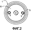
Фиг.2 иллюстрирует пример Фиг.1, вид со стороны задней поверхности накладки.Figure 2 illustrates an example of Figure 1, a side view of the rear surface of the lining.
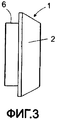
Фиг.3 иллюстрирует пример Фиг.1, вид сбоку.Figure 3 illustrates an example of Figure 1, side view.
Фиг.4 иллюстрирует пример Фиг.1 как боковое сечение.Figure 4 illustrates an example of Figure 1 as a side section.
Фиг.5 иллюстрирует часть Фиг.4.Figure 5 illustrates part of Figure 4.
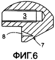
Фиг.6 иллюстрирует вариант выполнения углубления.6 illustrates an embodiment of a recess.
Фиг.7 иллюстрирует другой вариант выполнения углубления.7 illustrates another embodiment of a recess.
Описание изобретенияDescription of the invention
Фиг.1 иллюстрирует пример накладки 1 по изобретению, рассматриваемый со стороны передней поверхности 2. Фиг.2 иллюстрирует тот же самый пример, рассматриваемый со стороны задней поверхности, в то время как Фиг.3 иллюстрирует его сбоку. В этом варианте осуществления образованы два резьбовых отверстия 3 для соединительных деталей способом, известным в уровне техники. Винты и болты представляют собой обычные соединительные детали. Кроме того, имеется резьбовое отверстие 4 для шпинделя ручки в центре накладки. Таким образом, накладка в этом примере предназначена для противоположной стороны двери, когда другая сторона имеет ручку в том же самом отверстии, проделанном механическим способом. Накладка по изобретению также может естественно быть осуществлена каким-либо другим способом. Часть накладки, которая продолжается по краю отверстия, проделанного механическим способом, содержит углубление 5. Углубление расположено на установочной поверхности накладки, которая предназначена для крепления на установочном основании, то есть на поверхности двери. Углубление образует контур так, что он окружает отверстие, проделанное механическим способом, когда накладка прикреплена к установочному основанию.Figure 1 illustrates an example of a
Фиг.4 иллюстрирует сечение накладки, в то время как Фиг.5 иллюстрирует часть Фиг.4. Между дном углубления 5 и передней поверхностью 2 накладки находится шейка из материала 7, которая гнется, когда предпринята попытка, чтобы отжать накладку от установочного основания, используя инструмент взлома типа лома. Попытка заключается в том, чтобы вставить инструмент взлома между установочным основанием и накладкой, чтобы иметь хорошую опорную поверхность для того, чтобы произвести взлом при помощи инструмента. Однако формирование хорошей опорной поверхности ухудшается из-за углубления 5 и наличия гнущейся шейки из материала 1, что делает более трудным отжатие накладки от установочной основы.FIG. 4 illustrates a cross section of a patch, while FIG. 5 illustrates a portion of FIG. 4. Between the bottom of the
Фиг.5 иллюстрирует углубление 5 с прямоугольным сечением. Фиг.6 иллюстрирует углубление 8 с треугольным сечением, в котором вершина треугольника образует дно углубления. Фиг.1 иллюстрирует углубление 9 с округлым дном. Как можно видеть, существует множество различных вариантов выполнения углубления. Также могут быть использованы формы углубления, отличные от проиллюстрированных на чертежах.5 illustrates a
В примерах, иллюстрированных на чертежах, накладка также содержит вставляющуюся часть 6, расположенную так, чтобы быть плотно вставленной в отверстие, проделанное механическим способом в установочном основании. Вставляющаяся часть 6 увеличивает безопасность против взлома, потому что она делает более трудным отжатие накладки 1 от установочного основания. Однако накладка по изобретению может также быть реализована без вставляющейся части.In the examples illustrated in the drawings, the pad also includes an
Из вышеупомянутого очевидно, что изобретение не ограничено вариантами осуществления, описанными в этом тексте, но может быть осуществлено во многих других различных вариантах в пределах объема защиты изобретения.From the foregoing, it is obvious that the invention is not limited to the embodiments described herein, but can be implemented in many other various embodiments within the scope of protection of the invention.
Claims (5)
Applications Claiming Priority (2)
| Application Number | Priority Date | Filing Date | Title |
|---|---|---|---|
| FI20065584A FI121244B (en) | 2006-09-22 | 2006-09-22 | Cover plate |
| FI20065584 | 2006-09-22 |
Publications (2)
| Publication Number | Publication Date |
|---|---|
| RU2007135204A RU2007135204A (en) | 2009-03-27 |
| RU2425202C2 true RU2425202C2 (en) | 2011-07-27 |
Family
ID=37067235
Family Applications (1)
| Application Number | Title | Priority Date | Filing Date |
|---|---|---|---|
| RU2007135204/12A RU2425202C2 (en) | 2006-09-22 | 2007-09-21 | Pad |
Country Status (7)
| Country | Link |
|---|---|
| EP (1) | EP1903166B1 (en) |
| AT (1) | ATE472649T1 (en) |
| DE (1) | DE602007007413D1 (en) |
| DK (1) | DK1903166T3 (en) |
| FI (1) | FI121244B (en) |
| NO (1) | NO340650B1 (en) |
| RU (1) | RU2425202C2 (en) |
Families Citing this family (1)
| Publication number | Priority date | Publication date | Assignee | Title |
|---|---|---|---|---|
| UA160094U (en) * | 2024-09-19 | 2025-08-06 | Товариство З Обмеженою Відповідальністю "Аксор Індастрі" | FRONT COVER FOR HARDWARE |
Citations (5)
| Publication number | Priority date | Publication date | Assignee | Title |
|---|---|---|---|---|
| GB575203A (en) * | 1944-03-04 | 1946-02-07 | Evered & Co Ltd | Improvements relating to door latch or latch and lock actuating mechanisms |
| DE9406584U1 (en) * | 1994-04-20 | 1994-07-28 | Emka Beschlagteile Gmbh & Co. Kg, 42551 Velbert | Lock for control cabinet doors |
| CN2418197Y (en) * | 2000-01-25 | 2001-02-07 | 杨光 | Opening-closing device for keyhole of puzzle lock |
| DE202004005030U1 (en) * | 2004-03-31 | 2004-06-03 | Emka Beschlagteile Gmbh & Co. Kg | Two-part cam lock |
| RU2283407C1 (en) * | 2004-12-21 | 2006-09-10 | Михаил Юрьевич Рылеев | Protective armor covering plate for cylinder lock |
Family Cites Families (3)
| Publication number | Priority date | Publication date | Assignee | Title |
|---|---|---|---|---|
| GB191122002A (en) * | 1911-10-06 | 1912-05-16 | John Malachy Morris | Improvements in and connected with Cylinder Locks. |
| DE3345917A1 (en) * | 1983-12-20 | 1985-06-27 | Gebrüder Goldschmidt Baubeschläge GmbH, 5628 Heiligenhaus | Fitting for windows or doors |
| DE9204590U1 (en) * | 1992-04-03 | 1992-06-11 | Krone Ag, 14167 Berlin | Locking device for cabinets, especially cable distribution boxes |
-
2006
- 2006-09-22 FI FI20065584A patent/FI121244B/en active IP Right Grant
-
2007
- 2007-09-11 EP EP07116101A patent/EP1903166B1/en active Active
- 2007-09-11 AT AT07116101T patent/ATE472649T1/en not_active IP Right Cessation
- 2007-09-11 DE DE602007007413T patent/DE602007007413D1/en active Active
- 2007-09-11 DK DK07116101.2T patent/DK1903166T3/en active
- 2007-09-21 RU RU2007135204/12A patent/RU2425202C2/en active
- 2007-09-24 NO NO20074839A patent/NO340650B1/en unknown
Patent Citations (5)
| Publication number | Priority date | Publication date | Assignee | Title |
|---|---|---|---|---|
| GB575203A (en) * | 1944-03-04 | 1946-02-07 | Evered & Co Ltd | Improvements relating to door latch or latch and lock actuating mechanisms |
| DE9406584U1 (en) * | 1994-04-20 | 1994-07-28 | Emka Beschlagteile Gmbh & Co. Kg, 42551 Velbert | Lock for control cabinet doors |
| CN2418197Y (en) * | 2000-01-25 | 2001-02-07 | 杨光 | Opening-closing device for keyhole of puzzle lock |
| DE202004005030U1 (en) * | 2004-03-31 | 2004-06-03 | Emka Beschlagteile Gmbh & Co. Kg | Two-part cam lock |
| RU2283407C1 (en) * | 2004-12-21 | 2006-09-10 | Михаил Юрьевич Рылеев | Protective armor covering plate for cylinder lock |
Also Published As
| Publication number | Publication date |
|---|---|
| FI121244B (en) | 2010-08-31 |
| ATE472649T1 (en) | 2010-07-15 |
| DE602007007413D1 (en) | 2010-08-12 |
| EP1903166A2 (en) | 2008-03-26 |
| RU2007135204A (en) | 2009-03-27 |
| EP1903166A3 (en) | 2008-10-29 |
| FI20065584A0 (en) | 2006-09-22 |
| NO340650B1 (en) | 2017-05-22 |
| DK1903166T3 (en) | 2010-10-11 |
| NO20074839L (en) | 2008-03-24 |
| EP1903166B1 (en) | 2010-06-30 |
| FI20065584L (en) | 2008-03-23 |
Similar Documents
| Publication | Publication Date | Title |
|---|---|---|
| US4629231A (en) | Security plate for a door | |
| US6634683B1 (en) | Sash lock with hidden mounting screws | |
| US4720129A (en) | Improved two piece security plate for a door | |
| US7448235B2 (en) | Meter box locking assembly | |
| RU2425202C2 (en) | Pad | |
| CA2122293A1 (en) | Latch guard for outwardly opening doors | |
| US20090154178A1 (en) | Method and apparatus to secure street light | |
| HU220051B (en) | Door hinge | |
| GB2290579A (en) | A door lock escutcheon having load transmitting means | |
| EP2166183B1 (en) | Handle for vehicle doors with reinforced frame | |
| JP5080342B2 (en) | Reinforcement structure of terminal lid in watt-hour meter | |
| GB2347458A (en) | Vehicle bonnet lock device | |
| CN212726131U (en) | Novel distribution box | |
| JP3503563B2 (en) | Vehicle door handle anti-theft structure | |
| KR200404488Y1 (en) | A Single Body Type Latch Cover | |
| GB2346927A (en) | Actuating mechanism for lock | |
| EP3241963B1 (en) | Lock with multiple mounting plates | |
| KR100737824B1 (en) | Secure upper pivot hinge | |
| GB2437167A (en) | Door handle assembly | |
| EP1455036A1 (en) | Lock protection device | |
| KR200421490Y1 (en) | Secure upper pivot hinge | |
| KR200217149Y1 (en) | Computer case | |
| FI124444B (en) | LOCKING EQUIPMENT | |
| JP2005126995A (en) | Mounting reinforcement structure of cylinder lock | |
| GB2266332A (en) | Security hasp arrangement |