RU2425230C1 - Energy conversion method - Google Patents
Energy conversion method Download PDFInfo
- Publication number
- RU2425230C1 RU2425230C1 RU2010114317/06A RU2010114317A RU2425230C1 RU 2425230 C1 RU2425230 C1 RU 2425230C1 RU 2010114317/06 A RU2010114317/06 A RU 2010114317/06A RU 2010114317 A RU2010114317 A RU 2010114317A RU 2425230 C1 RU2425230 C1 RU 2425230C1
- Authority
- RU
- Russia
- Prior art keywords
- working fluid
- sorbent
- turbine
- working medium
- energy
- Prior art date
Links
Images
Landscapes
- Engine Equipment That Uses Special Cycles (AREA)
Abstract
Description
Изобретение относится преимущественно к способам преобразования тепловой энергии в механическую (электрическую), преимущественно к ядерным энергетическим установкам и системам энергообеспечения на их основе и предназначено для обеспечения тепловой и электрической энергией потребителей, имеющих неравномерную энергетическую нагрузку.The invention relates primarily to methods of converting thermal energy into mechanical (electrical) energy, mainly to nuclear power plants and energy supply systems based on them, and is intended to provide thermal and electric energy to consumers having an uneven energy load.
Известны способы преобразования тепловой энергии в механическую, в том числе в ядерных энергоустановках, преобразующие первичную энергию в электрическую, которая запасается в электроаккумуляторах и затем по необходимости выводится различным потребителям электроэнергии. Значительный потенциал имеют ядерные энергоисточники, которые выгодно использовать при постоянной нагрузке, в то время как в энергосистеме существуют дневные пики и ночные провалы мощности. Из особенностей работы ядерных энергогенерирующих систем известна проблема поддержания работы ядерных реакторов на постоянной мощности при значительной разнице во временных графиках выработки и потребления энергии. Таким образом, возникает задача создания способов преобразования энергии, энергоаккумулирующих установок и систем, способных обеспечивать потребителя различными видами энергии в требуемом по условиям потребления неравномерном режиме вне зависимости от графика выработки первичной энергии.Known methods for converting thermal energy into mechanical energy, including in nuclear power plants, converting primary energy into electrical energy, which is stored in electric batteries and then, if necessary, is output to various consumers of electricity. Nuclear energy sources have significant potential, which are advantageous to use under constant load, while in the power system there are day peaks and night power dips. Of the features of the operation of nuclear power generating systems, the known problem of maintaining the operation of nuclear reactors at constant power with a significant difference in the time schedules of energy production and consumption. Thus, the task arises of creating energy conversion methods, energy storage plants and systems that can provide consumers with various types of energy in the uneven mode required by the consumption conditions, regardless of the schedule for primary energy generation.
Выравнивание графика нагрузок энергоисточников за счет применения традиционных способов накопления электроэнергии или теплоаккумулирования увеличивает стоимость производства энергии и усложняет регламент работы.Aligning the load schedule of energy sources through the use of traditional methods of energy storage or heat storage increases the cost of energy production and complicates the work schedule.
В частности, предложен способ работы электростанции с водородным аккумулированием энергии, заключающийся в том, что воду разлагают на кислород и водород, отличающийся тем, что с целью повышения эффективности создают замкнутый цикл, где воду нагнетают насосом в пароохладитель и электролизер, из которого водород и кислород, как компоненты разложения воды, собирают в резервуары для раздельного хранения, сжигают в камере сгорания, а продукты сгорания в виде перегретого водяного пара направляют в пароохладитель, где впрыскивают воду и охлаждают перегретый водяной пар, энергию которого посредством паровой турбины, генератора, конденсатора и электрокотла преобразуют в электрическую и тепловую энергию, а конденсат сливают в конденсатную емкость (заявка РФ на изобретение №99102865, дата публикации 2000.12.20). Недостатком данного решения является высокая стоимость и низкая эффективность аккумулирования энергии, что связано с большими затратами на создание и эксплуатацию электролизеров (до 3000 дол. США/кВт) и систем хранения водорода и кислорода, а также относительно низким кпд паротурбинного цикла.In particular, a method of operating a power plant with hydrogen energy storage is proposed, which consists in decomposing water into oxygen and hydrogen, characterized in that in order to increase efficiency, they create a closed cycle where water is pumped into a desuperheater and an electrolyzer from which hydrogen and oxygen as components of water decomposition, they are collected in separate storage tanks, burned in the combustion chamber, and the combustion products in the form of superheated water vapor are sent to a desuperheater, where water and cooling are injected superheated water vapor is generated, the energy of which is converted into electric and thermal energy by means of a steam turbine, generator, condenser and electric boiler, and the condensate is drained into a condensate tank (RF application for invention No. 99102865, publication date 2000.12.20). The disadvantage of this solution is the high cost and low efficiency of energy storage, which is associated with high costs for the creation and operation of electrolyzers (up to 3000 US dollars / kW) and hydrogen and oxygen storage systems, as well as the relatively low efficiency of the steam turbine cycle.
Более экономичное решение предложено в патенте РФ на изобретение №2023387 (дата публикации 1994.11.30), в котором перед подачей углекислого газа в теплицу осуществляют его многоступенчатое сжатие с промежуточным охлаждением в водоуглекислотных теплообменниках, аккумулирование сжиженного углекислого газа и его хранение, при этом после хранения осуществляют нагрев его в солнечном коллекторе для получения углекислотного пара, который направляют в углекислотную турбину с регулируемым давлением на выхлопе турбин. Недостатками данного решения являются относительно низкий кпд углекислотного цикла и необходимость подвода углекислоты от стороннего источника.A more economical solution is proposed in the RF patent for invention No. 2023387 (publication date 1994.11.30), in which, before carbon dioxide is supplied to the greenhouse, it is multistage compressed with intermediate cooling in water-carbon dioxide heat exchangers, liquefied carbon dioxide is accumulated and stored, after storage they are heated in a solar collector to produce carbon dioxide vapor, which is sent to a carbon dioxide turbine with adjustable pressure on the turbine exhaust. The disadvantages of this solution are the relatively low efficiency of the carbon dioxide cycle and the need to supply carbon dioxide from an external source.
Известен также способ энергоаккумулирования, реализованный в установке, содержащей турбину, приемник рабочего тела, подключенный к выходу турбины, компрессор и охлаждающий теплообменник, соединенный с аккумулятором сжиженного рабочего тела, к которому подключен основной нагнетатель, установленный перед нагревающим теплообменником, включенным перед турбиной, компрессор соединен с приемником рабочего тела, выполненным в виде емкости, заполненной сорбентом рабочего тела, в которой размещен встроенный теплообменник, включенный между основным нагнетателем и нагревающим теплообменником (патент РФ на изобретение №2273742, дата публикации 10.04.2006. Бюл. №10).There is also known a method of energy storage implemented in an installation comprising a turbine, a working fluid receiver connected to the turbine outlet, a compressor and a cooling heat exchanger connected to a liquefied working fluid accumulator, to which a main supercharger is installed, installed in front of a heating heat exchanger connected in front of the turbine, the compressor is connected with the receiver of the working fluid, made in the form of a container filled with a sorbent of the working fluid, in which a built-in heat exchanger is placed, connected between novnym blower and the heating heat exchanger (RF patent №2273742, publication date 10.04.2006. Bul. №10).
Недостатками данного решения являются относительно большой удельный расход рабочего тела углекислотного цикла, связанный с низкой теплотой испарения углекислоты, необходимость компримирования рабочего тела и хранения жидкой углекислоты.The disadvantages of this solution are the relatively high specific consumption of the working fluid of the carbon dioxide cycle, associated with the low heat of vaporization of carbon dioxide, the need to compress the working fluid and storage of liquid carbon dioxide.
Задача изобретения - создать способ преобразования тепловой энергии в механическую, в котором устранены указанные выше недостатки, и создать условия эффективного повышения коэффициента использования энергоисточника.The objective of the invention is to create a method of converting thermal energy into mechanical energy, which eliminates the above disadvantages, and create conditions for effectively increasing the utilization of the energy source.
Поставленная задача решается тем, что в способе преобразования тепловой энергии в механическую, в котором в замкнутом цикле с помощью тепловой энергии проводят нагрев и испарение рабочего тела, которое подают затем на расширение в турбину, после которой рабочее тело сорбируют в сорбенте, конденсируют и нагнетают на повторный нагрев и испарение, в процессе конденсации рабочего тела одновременно ведут сорбцию части рабочего тела в сорбенте, обладающем гидрофильностью.The problem is solved in that in the method of converting thermal energy into mechanical energy, in which, in a closed cycle, thermal energy is used to heat and evaporate the working fluid, which is then fed to the expansion in the turbine, after which the working fluid is sorbed in the sorbent, condensed and pumped onto reheating and evaporation, in the process of condensation of the working fluid at the same time they sorb part of the working fluid in a sorbent with hydrophilicity.
Кроме того:Besides:
- периодически удаляют рабочее тело из гидрофильного сорбента путем его нагрева;- periodically remove the working fluid from the hydrophilic sorbent by heating it;
- нагрев гидрофильного сорбента ведут с помощью рабочего тела, отбираемого в процессе расширения из турбины;- heating the hydrophilic sorbent is carried out using a working fluid, selected during the expansion from the turbine;
- в качестве рабочего тела применяют водяной пар или его смесь с неконденсируемыми газами, которые выбирают из ряда, содержащего аммиак, перфторуглероды, диоксид углерода, углеводороды, благородные газы;- water vapor or its mixture with non-condensable gases, which are selected from the series containing ammonia, perfluorocarbons, carbon dioxide, hydrocarbons, and noble gases, is used as a working fluid;
- в качестве сорбента выбирают любое вещество из ряда молекулярное сито, цеолит, силикагель, спирт, ацетон, галогениды щелочных или щелочноземельных металлов, этаноламин, щелочи, нитраты или сочетание перечисленных материалов;- as a sorbent, choose any substance from the range of molecular sieve, zeolite, silica gel, alcohol, acetone, alkali or alkaline earth metal halides, ethanolamine, alkali, nitrates, or a combination of these materials;
- нагрев и испарение рабочего тела ведут путем конвективного нагрева через теплообменные поверхности;- heating and evaporation of the working fluid is carried out by convective heating through heat exchange surfaces;
- в процессе конденсации поддерживают давление ниже 0.1 МПа;- in the process of condensation maintain a pressure below 0.1 MPa;
- сорбцию рабочего тела ведут во время повышения механической нагрузки на турбину.- sorption of the working fluid is carried out while increasing the mechanical load on the turbine.
Примером реализации изобретения служит способ преобразования энергии, описанный ниже.An example implementation of the invention is the method of energy conversion, described below.
В излагаемом примере осуществления изобретения в качестве рабочего тела применяется водяной пар, что позволяет охарактеризовать особенности реализации изобретения применительно к процессам применения расширительных машин, в частности, на ядерных энергоустановках.In the described embodiment of the invention, water vapor is used as the working fluid, which allows us to characterize the features of the invention as applied to the processes of application of expansion machines, in particular, in nuclear power plants.
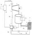
На чертеже дано схемное решение предложенного способа преобразования энергии.The drawing shows a schematic solution of the proposed method of energy conversion.
Способ осуществляется следующим образом.The method is as follows.
Проводят расширение водяного пара в турбине 1, а затем конденсируют водяной пар в конденсаторе 2 при давлении преимущественно ниже атмосферного за счет отвода тепла конденсации с помощью охлаждающего теплоносителя 3, проводя одновременно сорбцию части рабочего тела в сорбенте 4 с возможностью его охлаждения с помощью охлаждающего теплоносителя 5, подавая водяной пар к сорбенту по трубопроводу 6, после чего сконденсированный водяной пар с помощью насоса 7 подают на регенеративный подогрев с помощью отбора водяного пара 8 в подогревателе 9, а затем возвращают на испарение в парогенераторе 10 с помощью тепловой энергии 12. В процессе реализации излагаемого способа преобразования энергии используют возможности нагрева сорбента 4 с помощью теплоносителя 14, нагреваемого отбором водяного пара 8 или путем непосредственной подачи водяного пара в сорбент 4. Увеличение мощности паровой турбины 1 во время повышения механической нагрузки на турбину ведут как за счет изменения подвода водяного пара с помощью стопорно-регулирующего клапана 11, так и за счет снижения давления на выхлопе турбины в процессе конденсации, при которой поддерживают давление ниже 0.1 МПа за счет проведения сорбции водяного пара в сорбенте 4 путем изменения подачи водяного пара по трубопроводу 6 через регулирующее устройство 13, в качестве которого может быть использован тарельчатый клапан или штоковый вентиль или любое другое устройство, влияющее на гидравлическое сопротивление прохождению водяного пара. При снижении мощности турбины 1 увеличивают отбор водяного пара 8 для нагрева сорбента 4 с целью восстановления его сорбционной емкости.Water vapor is expanded in turbine 1, and then water vapor is condensed in
Для турбины К-1000-60/1.500-1 ХТЗ (3 ЦНД) энергоблока АЭС мощностью 1000 МВт дополнительное увеличение мощности при снижении давления отработавшего пара на -1 кПа составляет 12,75 МВт (1,28%).For the K-1000-60 / 1.500-1 KhTZ turbine (3 TsND) of a nuclear power plant with a capacity of 1000 MW, an additional increase in power with a decrease in exhaust steam pressure of -1 kPa is 12.75 MW (1.28%).
В зависимости от выбранного компонента рабочего тела (вода, аммиак, диоксид углерода, углеводород и т.д.) сорбент 4 может быть как твердым (например, активированный уголь, цеолит, хлорид щелочного металла и т.д.), так и жидким (щелочной раствор, спирт, раствор этаноламина и др.), что может вызывать отличия в процессе сорбции рабочего тела 2. Например, в случае жидкого сорбента 4 для снижения тепловых потерь в режиме десорбции может применяться дефлегмация десорбируемого рабочего тела, которая, в свою очередь, может сопровождаться регенеративным нагревом.Depending on the selected component of the working fluid (water, ammonia, carbon dioxide, hydrocarbon, etc.), the sorbent 4 can be either solid (for example, activated carbon, zeolite, alkali metal chloride, etc.), or liquid ( alkaline solution, alcohol, ethanolamine solution, etc.), which can cause differences in the process of sorption of the working
Сорбент выбирается из материалов, обладающих гидрофильностью (хорошей смачиваемостью водой). В этот ряд входят вещества с ионными кристаллическими решетками (оксиды, гидроксиды, силикаты, сульфаты, фосфаты, глины и т.д.), вещества с полярными группами - ОН, - СООН, - NO2 и др. Две несмешивающиеся фазы (гидрофильная и гидрофобная, например, присущая находящимся в технических контурах маслам) будут находиться в таком состоянии, где поверхность их контакта будет минимальной, что позволит уменьшить влияние таких микропримесей в рабочем теле как техническое масло на эффективность и динамические характеристики сорбента.The sorbent is selected from materials with hydrophilicity (good wettability with water). This series includes substances with ionic crystal lattices (oxides, hydroxides, silicates, sulfates, phosphates, clays, etc.), substances with polar groups — OH, —COOH, —NO 2 , etc. Two immiscible phases (hydrophilic and hydrophobic, for example, inherent to oils in technical circuits) will be in a state where their contact surface will be minimal, which will reduce the influence of such microimpurities in the working fluid as technical oil on the efficiency and dynamic characteristics of the sorbent.
В качестве сорбента, как уже упоминалось выше, может быть выбрано любое вещество из ряда активированный уголь, цеолит, вода, спирт, ацетон, галогениды щелочных или щелочноземельных металлов, этаноламин, щелочи, нитраты или сочетание перечисленных материалов.As a sorbent, as mentioned above, any substance from the range of activated carbon, zeolite, water, alcohol, acetone, halides of alkali or alkaline earth metals, ethanolamine, alkali, nitrates, or a combination of these materials can be selected.
В качестве рабочего тела целесообразно выбрать вещество с более низкой, чем у сорбента, точкой кипения из ряда углеводороды, вода, спирты, эфиры, фторхлоруглероды, перфторуглероды, аммиак, диоксид углерода или смесь перечисленных материалов.It is advisable to choose a substance with a lower boiling point from a series of hydrocarbons, water, alcohols, ethers, fluorochlorocarbons, perfluorocarbons, ammonia, carbon dioxide, or a mixture of the listed materials as a working fluid.
Учитывая относительно невысокие коэффициенты теплоотдачи к некоторым из предложенных сорбентов, а также с целью уменьшения потерь энергии при теплообмене сорбент 4 может содержать компоненты, увеличивающие его поверхность, выбранные из ряда: сетка, ребро, насечка, перфорированная пластина или их комбинация.Given the relatively low heat transfer coefficients for some of the proposed sorbents, as well as to reduce energy losses during heat transfer, the sorbent 4 may contain components that increase its surface, selected from the series: mesh, rib, notch, perforated plate, or a combination thereof.
Таким образом, указанный способ позволит повысить динамические и маневренные характеристики систем преобразования тепловой энергии в электрическую, снизить расход рабочего тела, уменьшить затраты на прокачку рабочего тела и потери, связанные с его недостаточным расширением в турбине, улучшить экономические показатели энергоустановок и систем энергообеспечения.Thus, this method will improve the dynamic and maneuverable characteristics of systems for converting thermal energy into electrical energy, reduce the flow of the working fluid, reduce the cost of pumping the working fluid and losses associated with its insufficient expansion in the turbine, and improve the economic performance of power plants and energy supply systems.
Claims (8)
Priority Applications (1)
| Application Number | Priority Date | Filing Date | Title |
|---|---|---|---|
| RU2010114317/06A RU2425230C1 (en) | 2010-04-12 | 2010-04-12 | Energy conversion method |
Applications Claiming Priority (1)
| Application Number | Priority Date | Filing Date | Title |
|---|---|---|---|
| RU2010114317/06A RU2425230C1 (en) | 2010-04-12 | 2010-04-12 | Energy conversion method |
Publications (1)
| Publication Number | Publication Date |
|---|---|
| RU2425230C1 true RU2425230C1 (en) | 2011-07-27 |
Family
ID=44753596
Family Applications (1)
| Application Number | Title | Priority Date | Filing Date |
|---|---|---|---|
| RU2010114317/06A RU2425230C1 (en) | 2010-04-12 | 2010-04-12 | Energy conversion method |
Country Status (1)
| Country | Link |
|---|---|
| RU (1) | RU2425230C1 (en) |
Citations (5)
| Publication number | Priority date | Publication date | Assignee | Title |
|---|---|---|---|---|
| US5007240A (en) * | 1987-12-18 | 1991-04-16 | Babcock-Hitachi Kabushiki Kaisha | Hybrid Rankine cycle system |
| US5243922A (en) * | 1992-07-31 | 1993-09-14 | Institute Of Gas Technology | Advanced staged combustion system for power generation from coal |
| RU2013572C1 (en) * | 1992-04-29 | 1994-05-30 | Фирма "Новые системы" | Power unit and its working medium preparation process |
| CA2122523A1 (en) * | 1993-04-30 | 1994-10-31 | Richard Allen Newby | System and method for cleaning hot fuel gas |
| RU2273742C1 (en) * | 2004-09-03 | 2006-04-10 | ООО "Центр КОРТЭС" | Energy-accumulating plant |
-
2010
- 2010-04-12 RU RU2010114317/06A patent/RU2425230C1/en not_active IP Right Cessation
Patent Citations (5)
| Publication number | Priority date | Publication date | Assignee | Title |
|---|---|---|---|---|
| US5007240A (en) * | 1987-12-18 | 1991-04-16 | Babcock-Hitachi Kabushiki Kaisha | Hybrid Rankine cycle system |
| RU2013572C1 (en) * | 1992-04-29 | 1994-05-30 | Фирма "Новые системы" | Power unit and its working medium preparation process |
| US5243922A (en) * | 1992-07-31 | 1993-09-14 | Institute Of Gas Technology | Advanced staged combustion system for power generation from coal |
| CA2122523A1 (en) * | 1993-04-30 | 1994-10-31 | Richard Allen Newby | System and method for cleaning hot fuel gas |
| RU2273742C1 (en) * | 2004-09-03 | 2006-04-10 | ООО "Центр КОРТЭС" | Energy-accumulating plant |
Similar Documents
| Publication | Publication Date | Title |
|---|---|---|
| RU2495707C2 (en) | Method and device for separation of carbon dioxide from offgas at electric power station running on fossil fuel | |
| Xue et al. | Thermodynamic analysis and optimization of a two-stage organic Rankine cycle for liquefied natural gas cryogenic exergy recovery | |
| US8250847B2 (en) | Combined Brayton-Rankine cycle | |
| CN102016240B (en) | Method for generating energy by means of thermal cycles with high pressure and moderate temperature steam | |
| CN104061710A (en) | Method for providing steam power and device thereof | |
| CN201301785Y (en) | High-efficiency ocean thermal energy power-generation device | |
| CN114345079B (en) | Temperature and pressure swing adsorption device and method for capturing carbon dioxide in flue gas | |
| JP2011518270A5 (en) | ||
| RU2273742C1 (en) | Energy-accumulating plant | |
| CN103075216B (en) | Brayton-cascade steam Rankine combined cycle power generation system | |
| CN101509472A (en) | Disperse type low-temperature solar thermal power generation system and power generation technique | |
| CN102230400A (en) | Device for generating electricity by using dead steam discharged by steam turbine | |
| RU129998U1 (en) | COMBINED STEAM-GAS-TURBINE INSTALLATION ON HYDROTHERMAL ALUMINUM PRODUCTS | |
| KR20140134862A (en) | Drying sludge apparatus | |
| KR101528935B1 (en) | Cryogenic cogeneration system | |
| CN103089355B (en) | Steam Rankine-low boiling working fluid Rankine combined cycle generating unit | |
| CN103990372B (en) | The system of ammonia process carbon trapping is carried out in the generating of solar seawater desalination assistant coal | |
| KR101613201B1 (en) | Desalination System For Power Plant Using Combined Cycle | |
| CN104153957A (en) | Novel temperature difference energy collecting cycle power generation device and power generation method thereof | |
| CN202108547U (en) | Low-temperature generating unit | |
| RU2425230C1 (en) | Energy conversion method | |
| CN202100286U (en) | Low-pressure heating device of power plant | |
| CN113882921A (en) | Low-temperature circulating power generation system and method using carbon dioxide gas as working medium | |
| CN103075213A (en) | Cascade type steam Rankine combined cycle generating device | |
| CN108868933B (en) | Coal-fired decarbonization and waste heat utilization power generation system integrating supercritical CO₂ and heat pump |
Legal Events
| Date | Code | Title | Description |
|---|---|---|---|
| MM4A | The patent is invalid due to non-payment of fees |
Effective date: 20210413 |