RU2425232C1 - Method of combustion arrangement in engine with spark ignition - Google Patents
Method of combustion arrangement in engine with spark ignition Download PDFInfo
- Publication number
- RU2425232C1 RU2425232C1 RU2009147642/06A RU2009147642A RU2425232C1 RU 2425232 C1 RU2425232 C1 RU 2425232C1 RU 2009147642/06 A RU2009147642/06 A RU 2009147642/06A RU 2009147642 A RU2009147642 A RU 2009147642A RU 2425232 C1 RU2425232 C1 RU 2425232C1
- Authority
- RU
- Russia
- Prior art keywords
- combustion
- engine
- insert
- spark
- combustion process
- Prior art date
Links
- 238000002485 combustion reaction Methods 0.000 title claims abstract description 41
- 238000000034 method Methods 0.000 title claims abstract description 20
- 239000000203 mixture Substances 0.000 claims abstract description 14
- 239000002826 coolant Substances 0.000 claims description 3
- 238000009825 accumulation Methods 0.000 abstract description 6
- 230000000694 effects Effects 0.000 abstract description 3
- 239000000446 fuel Substances 0.000 abstract description 3
- 239000000110 cooling liquid Substances 0.000 abstract 1
- 239000000126 substance Substances 0.000 abstract 1
- 230000035939 shock Effects 0.000 description 6
- 239000007789 gas Substances 0.000 description 5
- 238000005474 detonation Methods 0.000 description 3
- 238000002474 experimental method Methods 0.000 description 3
- 238000000926 separation method Methods 0.000 description 3
- 238000013021 overheating Methods 0.000 description 2
- 230000001133 acceleration Effects 0.000 description 1
- 230000001934 delay Effects 0.000 description 1
- 230000002452 interceptive effect Effects 0.000 description 1
- TVMXDCGIABBOFY-UHFFFAOYSA-N octane Chemical compound CCCCCCCC TVMXDCGIABBOFY-UHFFFAOYSA-N 0.000 description 1
- 238000007789 sealing Methods 0.000 description 1
- 230000001629 suppression Effects 0.000 description 1
Images
Classifications
-
- Y—GENERAL TAGGING OF NEW TECHNOLOGICAL DEVELOPMENTS; GENERAL TAGGING OF CROSS-SECTIONAL TECHNOLOGIES SPANNING OVER SEVERAL SECTIONS OF THE IPC; TECHNICAL SUBJECTS COVERED BY FORMER USPC CROSS-REFERENCE ART COLLECTIONS [XRACs] AND DIGESTS
- Y02—TECHNOLOGIES OR APPLICATIONS FOR MITIGATION OR ADAPTATION AGAINST CLIMATE CHANGE
- Y02T—CLIMATE CHANGE MITIGATION TECHNOLOGIES RELATED TO TRANSPORTATION
- Y02T10/00—Road transport of goods or passengers
- Y02T10/10—Internal combustion engine [ICE] based vehicles
- Y02T10/12—Improving ICE efficiencies
Landscapes
- Combustion Methods Of Internal-Combustion Engines (AREA)
Abstract
Description
Изобретение относится к двигателестроению.The invention relates to engine building.
Известно, что детонационная волна - это ударная волна, поддерживаемая во времени энергией сгорающего в ее фронте топлива.It is known that a detonation wave is a shock wave supported in time by the energy of the fuel burning in its front.
В настоящее время нет единой точки зрения на природу зарождения ударной волны в двигателе.Currently, there is no single point of view on the nature of the origin of a shock wave in an engine.
Одни считают, что ударная волна зарождается в результате самовоспламенения порций заряда, сгорающих в последнюю очередь. В этом случае определяющую роль играют задержки самовоспламенения горючей смеси, и все мероприятия по снижению склонности двигателя к детонации нацелены на устранение возможности самовоспламенения последних порций до прихода к ним фронта пламени.Some believe that the shock wave arises as a result of self-ignition of the portions of charge that are burned last. In this case, the self-ignition delays of the combustible mixture play a decisive role, and all measures to reduce the tendency of the engine to detonate are aimed at eliminating the possibility of self-ignition of the last portions before the flame front comes to them.
Другие считают, что определяющую роль в зарождении ударной волны играют волновые процессы, происходящие в камере сгорания двигателя при горении. Фронт пламени распространяется с ускорением, создавая возмущения в форме элементарных волн давления. В результате аккумулирования этих волн зарождается ударная волна по механизму, схожему с механизмом зарождения ударной волны при горении горючих смесей в трубах.Others believe that the decisive role in the generation of a shock wave is played by wave processes that occur in the combustion chamber of the engine during combustion. The flame front propagates with acceleration, creating disturbances in the form of elementary pressure waves. As a result of the accumulation of these waves, a shock wave is generated by a mechanism similar to the mechanism of the generation of a shock wave during the combustion of combustible mixtures in pipes.
С этой точки зрения можно улучшить антидетонационные свойства двигателя путем воздействия на волновые процессы при горении, например, создавая препятствия (помехи) аккумулированию элементарных волн.From this point of view, it is possible to improve the antiknock properties of the engine by influencing wave processes during combustion, for example, creating obstacles (interference) to the accumulation of elementary waves.
Возможно, поэтому такие конструктивные приемы, как ступенчатый поршень или выступы (ребра) в камере сгорания (КС), снижают склонность двигателя к детонации.Perhaps, therefore, such constructive techniques as a stepped piston or protrusions (ribs) in the combustion chamber (CS) reduce the tendency of the engine to detonate.
Известен способ организации процесса сгорания путем разделения всего объема камеры сгорания на две или более части, причем разделение всего объема на малые объемы, зажигание и независимое друг от друга горение смеси малых объемов осуществляют временно до окончания активного тепловыделения, после чего объемы соединяют и догорание смеси проводят во всем объеме (см. RU 2187004, F02В 23/08, 2002).A known method of organizing the combustion process by dividing the entire volume of the combustion chamber into two or more parts, the separation of the entire volume into small volumes, ignition and independent combustion of the mixture of small volumes is carried out temporarily until active heat is released, after which the volumes are combined and the mixture is burned out in the entire volume (see RU 2187004, F02В 23/08, 2002).
Известен способ организации процесса постадийного сгорания в поршневом двигателе путем временного разделения камеры сгорания на свечную и бессвечные полости, зажигания от искры и временного независимого горения смеси в свечной полости, поочередного объединения полостей и зажигания смеси в бессвечных полостях горящими газами, догорания в объединенном объеме, причем независимое горение осуществляют до критического отношения давлений газов между полостями и зажигание смеси в очередной полости осуществляют горящими газами от предыдущих полостей с критической скоростью их истечения (RU 2232906, F02В 23/08, 2004).A known method of organizing a step-by-step combustion process in a piston engine by temporarily dividing the combustion chamber into a candle and non-spark cavity, igniting from a spark and temporarily independently burning the mixture in the candle cavity, sequentially combining the cavities and igniting the mixture in the candleless cavities by burning gases, burning out in the combined volume, independent combustion is carried out to a critical ratio of gas pressures between the cavities and the mixture is ignited in the next cavity by burning gases from the previous their cavities with a critical rate of their expiration (RU 2232906, F02В 23/08, 2004).
Способы имеют существенный недостаток. В таких способах трудно выдержать приемлемую температуру выступов в широком диапазоне режимов работы двигателя. Возможны их перегревы, что увеличивает вероятность возникновения калильного зажигания от поверхности. В предлагаемом способе организации сгорания этот недостаток устраняется.The methods have a significant drawback. In such methods, it is difficult to maintain an acceptable temperature of the protrusions in a wide range of engine operating modes. Overheating is possible, which increases the likelihood of ignition from the surface. In the proposed method of organizing combustion, this disadvantage is eliminated.
Задача изобретения - улучшение антидетонационных свойств двигателей с искровым зажиганием.The objective of the invention is to improve the antiknock properties of engines with spark ignition.
Для решения данной задачи предложен способ организации сгорания в двигателе с искровым зажиганием путем воспламенения от искры и турбулентного горения однородной или расслоенной смеси, в котором процесс горения осуществляют в камере сгорания, снабженной вставками, имеющими трубчатое поперечное сечение, по которым пропускают охлаждающую жидкость.To solve this problem, a method for organizing combustion in an engine with spark ignition by igniting from a spark and turbulent combustion of a homogeneous or layered mixture in which the combustion process is carried out in a combustion chamber equipped with inserts having a tubular cross section through which coolant is passed, is proposed.
Сущность способа организации сгорания состоит в том, что осуществляют зажигание от искры и обычное турбулентное горение однородной или расслоенной смеси. С целью создания препятствий аккумулированию элементарных волн давления камеру сгорания перегораживают с помощью специальной вставки, выполненной из трубки или нескольких трубок, по которым пропускают охлаждающая жидкость.The essence of the method of organizing combustion is that they carry out ignition from a spark and ordinary turbulent combustion of a homogeneous or layered mixture. In order to obstruct the accumulation of elementary pressure waves, the combustion chamber is partitioned off using a special insert made of a tube or several tubes through which coolant is passed.
В этом случае исключается перегрев поверхностей вставки, и вместе с тем конструкцией вставки можно воздействовать как на газодинамические, так и волновые процессы при горении.In this case, overheating of the surfaces of the insert is excluded, and at the same time, the design of the insert can affect both gas-dynamic and wave processes during combustion.
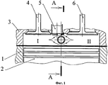
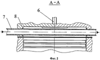
На фиг.1 и фиг.2 показана камера сгорания (КС), перегороженная вставкой по диагонали. КС включает: 1 - гильза цилиндра, 2 - поршневой комплект, 3 - головка цилиндра, 4 - выпускной клапан, 5 - свеча зажигания, 6 - впускной клапан, 7 - вставка.Figure 1 and figure 2 shows the combustion chamber (KS), partitioned by an insert diagonally. КС includes: 1 - cylinder liner, 2 - piston kit, 3 - cylinder head, 4 - exhaust valve, 5 - spark plug, 6 - intake valve, 7 - insert.
Вставка выполнена из трубки круглого сечения. Она разделяет КС на две полости - I и II. Полости сообщаются между собой через зазоры выше и ниже трубки. Герметизация вставки обеспечивается уплотнениями 8.The insert is made of a circular tube. It divides the CS into two cavities - I and II. The cavities communicate with each other through gaps above and below the tube. Sealing of the insert is provided by
Горение газовой смеси начинается в полости I. При обтекании вставки скорость газов увеличивается, что ведет к более быстрому догоранию смеси в полости II. Такая вставка существенно влияет на газодинамические процессы при горении. Вместе с тем такая вставка должна влиять и на волновые процессы при горении, создавая помехи в аккумулировании элементарных волн давления. Как газодинамические, так и волновые изменения в сгорании от данной вставки приведут к снижению склонности двигателя к детонации.Combustion of the gas mixture begins in cavity I. As the flow flows around the insert, the gas velocity increases, which leads to faster burning of the mixture in cavity II. Such an insert significantly affects the gas-dynamic processes during combustion. At the same time, such an insert should also influence wave processes during combustion, interfering with the accumulation of elementary pressure waves. Both gas-dynamic and wave changes in combustion from this insert will reduce the propensity of the engine to detonate.
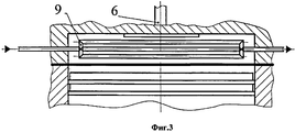
Разделение камеры сгорания на полости можно выполнить вставкой 9, выполненной из пучка трубок в форме радиатора, представленной на фиг.3. Такое исполнение окажет более сильное влияние на процесс сгорания.The separation of the combustion chamber into cavities can be performed by an
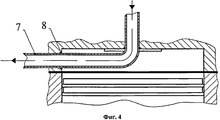
При модернизации камер сгорания серийных двигателей не всегда возможно обеспечить разделение камеры сгорания по диагонали. Поэтому можно выполнить любую другую доступную геометрическую форму вставки, например Г-образную форму вставки, показанную на фиг.4. При такой форме влияние вставки на газодинамические процессы при горении будет не столь значительно, как при диагональном расположении. Однако на волновые процессы такая вставка должна оказывать влияние, создавая препятствия аккумулированию элементарных волн давления.When upgrading the combustion chambers of serial engines, it is not always possible to ensure the diagonal separation of the combustion chamber. Therefore, any other available insert geometry can be made, for example, the L-shaped insert shape shown in FIG. 4. With this form, the effect of the insert on gas-dynamic processes during combustion will not be as significant as with a diagonal arrangement. However, such an insert should influence the wave processes, creating obstacles to the accumulation of elementary pressure waves.
Для подтверждения теоретических предположений были проведены опыты на двигателе с плоскоовальной камерой сгорания. Опыты проводились на выделенном цилиндре 4-цилиндрового двигателя в сопоставимых условиях на специальном топливе с октановым числом по моторному методу, равным 67 ед. Вставка была выполнена по схеме фиг.4 и представляла трубку с наружным диаметром 4 мм и длиной 60 мм. Угол зажигания по началу слышимой детонации в опытах со вставкой увеличился на 14 градусов поворота коленчатого вала, что подтверждает эффективность подавления детонации предлагаемым способом.To confirm theoretical assumptions, experiments were conducted on an engine with a flat oval combustion chamber. The experiments were carried out on a dedicated cylinder of a 4-cylinder engine under comparable conditions on special fuel with an octane number by the motor method equal to 67 units. The insert was made according to the scheme of figure 4 and was a tube with an outer diameter of 4 mm and a length of 60 mm The ignition angle at the beginning of audible detonation in experiments with the insert increased by 14 degrees of crankshaft rotation, which confirms the effectiveness of the suppression of detonation by the proposed method.
Claims (1)
Priority Applications (1)
| Application Number | Priority Date | Filing Date | Title |
|---|---|---|---|
| RU2009147642/06A RU2425232C1 (en) | 2009-12-21 | 2009-12-21 | Method of combustion arrangement in engine with spark ignition |
Applications Claiming Priority (1)
| Application Number | Priority Date | Filing Date | Title |
|---|---|---|---|
| RU2009147642/06A RU2425232C1 (en) | 2009-12-21 | 2009-12-21 | Method of combustion arrangement in engine with spark ignition |
Publications (1)
| Publication Number | Publication Date |
|---|---|
| RU2425232C1 true RU2425232C1 (en) | 2011-07-27 |
Family
ID=44753597
Family Applications (1)
| Application Number | Title | Priority Date | Filing Date |
|---|---|---|---|
| RU2009147642/06A RU2425232C1 (en) | 2009-12-21 | 2009-12-21 | Method of combustion arrangement in engine with spark ignition |
Country Status (1)
| Country | Link |
|---|---|
| RU (1) | RU2425232C1 (en) |
Citations (14)
| Publication number | Priority date | Publication date | Assignee | Title |
|---|---|---|---|---|
| GB1437867A (en) * | 1973-05-04 | 1976-06-03 | ||
| US4052972A (en) * | 1975-03-14 | 1977-10-11 | Fuji Jukogyo Kabushiki Kaisha | Internal combustion engine |
| DE3530805A1 (en) * | 1985-08-29 | 1987-03-12 | Kloeckner Humboldt Deutz Ag | Method for minimising the dead space in the combustion chamber of an internal combustion engine |
| EP0464497A1 (en) * | 1990-06-29 | 1992-01-08 | Isuzu Motors Limited | Diesel engine |
| DE4020262A1 (en) * | 1990-06-26 | 1992-01-09 | Daimler Benz Ag | Combustion chamber for IC engine - is formed by depression in piston crown |
| RU2008455C1 (en) * | 1991-01-03 | 1994-02-28 | Алтайский политехнический институт им.И.И.Ползунова | Swirl combustion chamber of diesel engine |
| RU2054126C1 (en) * | 1990-11-26 | 1996-02-10 | Фарид Фуатович Дебердеев | Method of operating internal combustion engine and internal combustion engine |
| RU2158372C1 (en) * | 1999-03-29 | 2000-10-27 | Военный автомобильный институт | Method of organizing working process in internal combustion carburetor engine |
| JP2004108225A (en) * | 2002-09-18 | 2004-04-08 | Daihatsu Motor Co Ltd | Combustion control device in compression ignition type internal combustion engine |
| RU2232906C1 (en) * | 2003-01-22 | 2004-07-20 | ГОУ СПО Новгородский гидромелиоративный техникум | Method to organize stage-by-stage combustion in piston engine |
| RU2235212C2 (en) * | 2002-09-30 | 2004-08-27 | Новгородский государственный университет им. Ярослава Мудрого | Internal combustion engine |
| JP2006329132A (en) * | 2005-05-27 | 2006-12-07 | Toyota Motor Corp | Internal combustion engine |
| RU2289758C1 (en) * | 2005-06-23 | 2006-12-20 | Михаил Иванович Весенгириев | Tubular-annular combustion chamber of gas-turbine engine |
| RU2359136C2 (en) * | 2006-12-25 | 2009-06-20 | Владимир Рудольфович Гальговский | Internal combustion engine and method of ice fuel combustion |
-
2009
- 2009-12-21 RU RU2009147642/06A patent/RU2425232C1/en not_active IP Right Cessation
Patent Citations (14)
| Publication number | Priority date | Publication date | Assignee | Title |
|---|---|---|---|---|
| GB1437867A (en) * | 1973-05-04 | 1976-06-03 | ||
| US4052972A (en) * | 1975-03-14 | 1977-10-11 | Fuji Jukogyo Kabushiki Kaisha | Internal combustion engine |
| DE3530805A1 (en) * | 1985-08-29 | 1987-03-12 | Kloeckner Humboldt Deutz Ag | Method for minimising the dead space in the combustion chamber of an internal combustion engine |
| DE4020262A1 (en) * | 1990-06-26 | 1992-01-09 | Daimler Benz Ag | Combustion chamber for IC engine - is formed by depression in piston crown |
| EP0464497A1 (en) * | 1990-06-29 | 1992-01-08 | Isuzu Motors Limited | Diesel engine |
| RU2054126C1 (en) * | 1990-11-26 | 1996-02-10 | Фарид Фуатович Дебердеев | Method of operating internal combustion engine and internal combustion engine |
| RU2008455C1 (en) * | 1991-01-03 | 1994-02-28 | Алтайский политехнический институт им.И.И.Ползунова | Swirl combustion chamber of diesel engine |
| RU2158372C1 (en) * | 1999-03-29 | 2000-10-27 | Военный автомобильный институт | Method of organizing working process in internal combustion carburetor engine |
| JP2004108225A (en) * | 2002-09-18 | 2004-04-08 | Daihatsu Motor Co Ltd | Combustion control device in compression ignition type internal combustion engine |
| RU2235212C2 (en) * | 2002-09-30 | 2004-08-27 | Новгородский государственный университет им. Ярослава Мудрого | Internal combustion engine |
| RU2232906C1 (en) * | 2003-01-22 | 2004-07-20 | ГОУ СПО Новгородский гидромелиоративный техникум | Method to organize stage-by-stage combustion in piston engine |
| JP2006329132A (en) * | 2005-05-27 | 2006-12-07 | Toyota Motor Corp | Internal combustion engine |
| RU2289758C1 (en) * | 2005-06-23 | 2006-12-20 | Михаил Иванович Весенгириев | Tubular-annular combustion chamber of gas-turbine engine |
| RU2359136C2 (en) * | 2006-12-25 | 2009-06-20 | Владимир Рудольфович Гальговский | Internal combustion engine and method of ice fuel combustion |
Similar Documents
| Publication | Publication Date | Title |
|---|---|---|
| US9567896B2 (en) | Method for modifying combustion chamber in a reciprocating piston internal combustion engine and resulting engine | |
| US9316144B2 (en) | Pre-chamber system for an internal combustion engine | |
| US9739192B2 (en) | Fuel combustion system, nozzle for prechamber assembly with curved orifices, and method of making same | |
| CN106050451B (en) | Control device for internal combustion engine | |
| CN102084100B (en) | Pre-chamber unit of a combustion engine | |
| CN109798177B (en) | Pre-chamber ignition apparatus and method for internal combustion engine | |
| US10047688B2 (en) | Ignition system for internal combustion engines | |
| PL2011989T3 (en) | Pulse detonation engine operating with a mix of fuel and air | |
| WO2014117177A1 (en) | Thermally stratified regenerative combustion chamber and method for modifying a combustion chamber in an internal combustion engine and resulting engine | |
| US9567939B2 (en) | Thermally stratified regenerative combustion chamber | |
| EP2998538A1 (en) | Pre-chamber of internal combustion engine | |
| RU2425232C1 (en) | Method of combustion arrangement in engine with spark ignition | |
| CN110173343A (en) | A kind of engine ignition room jet stream collision burning system | |
| CN113396274A (en) | Engine assembly | |
| CN105579683A (en) | Ignition system for low grade synthesis gas | |
| Jamrozik et al. | Numerical analysis of influence of prechamber geometry in IC engine with two-stage combustion system on engine work cycle parameters | |
| EP3037646B1 (en) | Method for operating internal combustion engines | |
| WO2011105897A3 (en) | Igniter for a rocket engine, method for ignition of a rocket engine | |
| JP7260331B2 (en) | Internal combustion engine with auxiliary combustion chamber | |
| de Oliveira et al. | A review of passive pre-chamber in turbulent jet ignition system applied on low emissions SI engines | |
| WO2023275630A1 (en) | Pulsed detonation device for internal combustion engine and method | |
| Atis | High-EGR dilution enabled by dual mode, turbulent jet ignition (DM-TJI) for high-efficiency internal combustion engines | |
| JP6898599B2 (en) | Engine control | |
| JP5780943B2 (en) | Ignition control device | |
| RU2232906C1 (en) | Method to organize stage-by-stage combustion in piston engine |
Legal Events
| Date | Code | Title | Description |
|---|---|---|---|
| MM4A | The patent is invalid due to non-payment of fees |
Effective date: 20121222 |