RU2425242C1 - Device for turning traction vector of double-flow jet turbine engine - Google Patents
Device for turning traction vector of double-flow jet turbine engine Download PDFInfo
- Publication number
- RU2425242C1 RU2425242C1 RU2010104542/06A RU2010104542A RU2425242C1 RU 2425242 C1 RU2425242 C1 RU 2425242C1 RU 2010104542/06 A RU2010104542/06 A RU 2010104542/06A RU 2010104542 A RU2010104542 A RU 2010104542A RU 2425242 C1 RU2425242 C1 RU 2425242C1
- Authority
- RU
- Russia
- Prior art keywords
- deflecting
- engine
- engine nacelle
- reversing
- flap
- Prior art date
Links
Images


Landscapes
- Structures Of Non-Positive Displacement Pumps (AREA)
Abstract
Description
Изобретение относится к устройствам для реверсирования и изменения направления вектора тяги авиационных турбореактивных двухконтурных двигателей.The invention relates to devices for reversing and changing the direction of the thrust vector of aircraft turbojet bypass engines.
Известно, что сопла с модернизированными реверсивными устройствами (РУ) могут быть использованы как средство повышения уровня летно-технических, маневренных и пилотажных характеристик самолетов, позволяющее обеспечить управляемость на режимах полета с малыми скоростями, где недостаточна эффективность аэродинамических органов управления.It is known that nozzles with upgraded reversing devices (RU) can be used as a means of increasing the level of flight-technical, maneuvering and flight characteristics of aircraft, which ensures controllability in low-speed flight modes, where aerodynamic control elements are not efficient enough.
Использование на самолете дополнительных к РУ устройств для отклонения вектора тяги (ОВТ) рассматривается как одна из возможностей улучшения летно-технических характеристик перспективных самолетов.The use of additional devices for thrust vector deviation (AE) on the aircraft is considered as one of the opportunities to improve the flight performance of promising aircraft.
Известно отклоняющее устройство, изменяющее направление истечения выхлопной струи, например сопло с отклонением вектора тяги компании Stage III Technologies L.C. (Патент США №6233920 от 22.05.2001 г.). Предложена конструкция створчатого типа, устанавливаемая на сопло. На полетных и взлетных режимах створки РУ формируют наружные стенки обтекателя мотогондолы. При включении реверса тяги происходит сдвигание створок вниз по потоку и разворот. Однако для отклонения выхлопной струи двухконтурного двигателя с большой степенью двухконтурности использование поворотного сопла затруднительно из-за его большой массы.A deflecting device is known that changes the direction of the exhaust stream, for example, a nozzle with a deviation of the thrust vector of Stage III Technologies L.C. (US Patent No. 6233920 dated 05/22/2001). A casement type design mounted on a nozzle is proposed. On flight and take-off modes, RU shutters form the outer walls of the nacelle fairing. When thrust reverse is turned on, the flaps shift downstream and turn. However, to deviate the exhaust jet of a bypass engine with a high bypass ratio, the use of a rotary nozzle is difficult due to its large mass.
Компания SNECMA Moteurs разработала реверсивное устройство и сопло турбореактивного двигателя (Патент США №6289670 от 18.09.2001 г.). Створки сопла в устройстве предусматривают большую регулировку площади сопла и управление изменением направления вектором тяги, что позволяет использовать это устройство на перспективных сверхзвуковых самолетах. Однако в этом патенте угол изменения направления вектора тяги расположен в небольших пределах.SNECMA Moteurs has developed a reversing device and a turbojet engine nozzle (US Patent No. 6289670 of September 18, 2001). The nozzle flaps in the device provide for large adjustment of the nozzle area and control of the direction of the thrust vector, which makes it possible to use this device on promising supersonic aircraft. However, in this patent, the angle of change of direction of the thrust vector is within small limits.
Наиболее близким аналогом того же назначения по конструкции, что и заявляемое техническое решение, является «Устройство реверсирования тяги двухконтурного турбореактивного двигателя» Патент РФ №2162537 от 04.06.1998 г. фирмы ИСПАНО - СЮИЗА АЭРОСТРЮКТЮР (Fr). Устройство включает цилиндрическую мотогондолу вентилятора наружного контура и центральное тело газогенератора внутреннего контура двигателя. Устройство содержит в задней части мотогондолы по периферии окна и на выходе кольцевое сопло. В окнах размещены реверсивные и отклоняющие створки, имеющие форму совкового типа, где реверсивные створки выполнены полыми и установлены в задней части каждого окна мотогондолы на поперечных осях. Каждая отклоняющая створка шарнирно связана на поперечной оси со своей реверсивной створкой. Кроме того, реверсивные и отклоняющие створки шарнирно соединены со средствами управления их перемещением. Данное устройство осуществляет заданное реверсирования тяги и относительно просто по конструкции. Основным недостатком устройства являются большие потери при высоких углах отклонения выхлопных струй на режиме ОВТ.The closest analogue of the same purpose in design as the claimed technical solution is the “Device for reversing the thrust of a dual-circuit turbojet engine” RF Patent No. 2162537 dated 06.06.1998 from the company ISPANO - SUIZA AEROSTRUCTURE (Fr). The device includes a cylindrical nacelle of the external circuit fan and the central body of the gas generator of the internal circuit of the engine. The device comprises an annular nozzle at the rear of the engine nacelle at the periphery of the window and at the exit. The windows are equipped with reversible and deflecting flaps, which have the shape of a scoop type, where the reversible flaps are hollow and are installed in the rear of each window of the nacelle on the transverse axes. Each deflecting leaf is pivotally connected on its transverse axis with its reversible leaf. In addition, the reversing and deflecting flaps are pivotally connected to controls for their movement. This device performs a predetermined reverse thrust and is relatively simple in design. The main disadvantage of the device is the large loss at high angles of deviation of the exhaust jets in the OBT mode.
Таким образом известные конструкции РУ уже не могут удовлетворять современным требованиям по обеспечению характеристик боковой устойчивости и поперечной управляемости на больших углах атаки современных самолетов, имеющих классические аэродинамические поверхности управления.Thus, the well-known design of the switchgear can no longer meet modern requirements for ensuring the characteristics of lateral stability and lateral controllability at large angles of attack of modern aircraft with classic aerodynamic control surfaces.
В основу изобретения положено решение задачи создания современного РУ с добавлением ему функций ОВТ.The basis of the invention is the solution to the problem of creating a modern reactor plant with the addition of the functions of OVT.
Это позволит повысить эффективность боковой устойчивости и поперечной управляемости самолета на больших углах атаки, улучшить его взлетно-посадочные характеристики на малых скоростях полета.This will increase the efficiency of lateral stability and lateral controllability of the aircraft at large angles of attack, improve its take-off and landing performance at low flight speeds.
Поставленная задача решается тем, что устройство поворота вектора тяги турбореактивного двухконтурного двигателя, включающего центральное тело газогенератора внутреннего контура и мотогондолу вентилятора наружного контура с кольцевым соплом на выходе, содержит в задней части мотогондолы по периферии окна и размещенные в окнах реверсивные и отклоняющие створки, имеющие форму совкового типа. Реверсивные створки закреплены в задней части каждого окна мотогондолы на поперечных осях. Каждая отклоняющая створка шарнирно связана на поперечной оси со своей реверсивной створкой. Кроме того, реверсивные и отклоняющие створки шарнирно соединены со средствами управления их перемещением.The problem is solved in that the device for turning the thrust vector of a turbojet bypass engine, which includes the central body of the gas generator of the internal circuit and the nacelle of the external circuit fan with an annular outlet, contains in the rear of the nacelle around the periphery of the window and reversible and deflecting shutters placed in the windows shovel type. Reversible flaps are fixed at the rear of each engine nacelle window on the transverse axes. Each deflecting leaf is pivotally connected on its transverse axis with its reversible leaf. In addition, the reversing and deflecting flaps are pivotally connected to controls for their movement.
Новым в изобретении является то, что каждая реверсивная створка снабжена окном, в котором установлена полая отклоняющая створка. Отклоняющая створка состоит из наружной и внутренней стенок с каналом между ними. Внешняя поверхность наружной стенки отклоняющей створки на режиме прямой тяги образует часть наружной поверхности мотогондолы. Вдоль продольных кромок окон мотогондолы между мотогондолой и центральным телом газогенератора тракт наружного контура двигателя разделен радиальными пилонами аэродинамического профиля, контактирующими при работе с реверсивными и отклоняющими створками. Средства управления перемещением реверсивных и отклоняющих створок выполнены в виде отдельных приводов поступательного движения. Каждая реверсивная створка соединена шарнирно задней кромкой с мотогондолой за своим окном через привод, размещенный в последней, и снабжена снаружи в передней части обтекателем в виде полого трехгранного кольцевого сектора. Наружная грань сектора на режимах прямой тяги и отклоняемого вектора тяги образует часть наружной поверхности мотогондолы, а две другие - соответственно внутренние переднюю и заднюю наклонные поверхности обтекателя. При этом отклоняющая створка размещена в реверсивной створке за обтекателем и связана шарнирно с расположенным в обтекателе приводом. На режиме прямой тяги внутренняя поверхность реверсивной створки и внутренняя поверхность внутренней стенки отклоняющей створки образуют части внутренней поверхности мотогондолы наружного контура двигателя.New in the invention is that each reversible leaf is provided with a window in which a hollow deflecting leaf is installed. The deflecting leaf consists of the outer and inner walls with a channel between them. The outer surface of the outer wall of the deflecting sash in direct traction mode forms part of the outer surface of the nacelle. Along the longitudinal edges of the windows of the nacelle between the nacelle and the central body of the gas generator, the path of the outer circuit of the engine is divided by radial pylons of the aerodynamic profile, which are in contact with reversing and deflecting wings. Means of controlling the movement of reversing and deflecting flaps are made in the form of separate translational drives. Each reversible leaf is pivotally connected with the trailing edge to the engine nacelle behind its window through a drive located in the latter, and is equipped with a cowl in the form of a hollow triangular ring sector outside the front part. The outer edge of the sector in the direct thrust and deflected thrust vector modes forms part of the outer surface of the nacelle, and the other two, respectively, the inner front and rear inclined surfaces of the fairing. In this case, the deflecting sash is placed in the reversing sash behind the cowl and is pivotally connected to the drive located in the cowl. In direct traction mode, the inner surface of the reversing leaf and the inner surface of the inner wall of the deflecting leaf form parts of the inner surface of the engine nacelle of the outer contour of the engine.
Выполнение каждой реверсивной и отклоняющей створок в виде формы совкового типа обеспечивает уменьшение растекания струй при истечении потока воздуха наружу из устройства.The implementation of each reversible and deflecting valves in the form of a scoop type provides a reduction in the spreading of jets when the air flow out of the device.
Снабжение реверсивной створки окном, в котором установлена полая отклоняющая створка, позволяет использовать окно мотогондолы не только для функции реверсирования, но и для выполнения функции ОВТ. Это позволяет, не изменяя габариты РУ, при незначительном увеличении массы получить новую функцию устройства.Providing the reversing sash with a window in which the hollow deflecting sash is installed, allows the use of the engine nacelle window not only for the reversal function, but also for performing the OBT function. This allows, without changing the dimensions of the switchgear, with a slight increase in mass, to obtain a new function of the device.
Выполнение отклоняющей створки из наружной и внутренней стенок с каналом между ними обеспечивает стабильные расходные характеристики канала при различных положениях створки.The implementation of the deflecting sash from the outer and inner walls with a channel between them provides stable flow characteristics of the channel at different positions of the sash.
Разделение тракта радиальными пилонами аэродинамического профиля вдоль продольных кромок окон мотогондолы наружного контура двигателя между мотогондолой и центральным телом газогенератора, контактирующими при работе с реверсивными и отклоняющими створками, обеспечивает разделение потока через окна мотогондолы в заданных секторах.The separation of the path by the radial pylons of the aerodynamic profile along the longitudinal edges of the windows of the engine nacelle of the outer contour of the engine between the engine nacelle and the central body of the gas generator in contact with reversing and deflecting wings, provides flow separation through the engine nacelle windows in predetermined sectors.
Выполнение средств управления перемещением реверсивной и отклоняющей створок в виде отдельных приводов поступательного движения позволяет обеспечивать управление РУ и ОВТ по заданной программе.The implementation of the means for controlling the movement of the reversing and deflecting sashes in the form of separate translational motion drives makes it possible to provide control of the switchgear and the reactive current circuit according to a given program.
Соединение каждой реверсивной створки шарнирно задней кромкой с мотогондолой за своим окном через привод, размещенный в последней, обеспечивает уменьшение аэродинамических потерь в каналах створок и окнах мотогондолы.The connection of each reversible leaf articulated by the trailing edge with the engine nacelle behind its window through a drive located in the latter provides a reduction in aerodynamic losses in the channels of the leaves and the windows of the engine nacelle.
Снабжение реверсивной створки снаружи в передней части обтекателем в виде полого трехгранного кольцевого сектора позволяет уменьшить потери на обтекание створок потоком воздуха на всех режимах.The supply of the reversing shutter outside the front part with a fairing in the form of a hollow trihedral annular sector allows to reduce losses due to the flow of air around the shutters in all modes.
Выполнение наружной грани сектора обтекателя в виде части кольцевой наружной поверхности мотогондолы обеспечивает непрерывность наружной поверхности последней.The implementation of the outer edge of the fairing sector in the form of a part of the annular outer surface of the nacelle ensures continuity of the outer surface of the latter.
Выполнение двух других граней сектора соответственно внутренними передней и задней наклонными поверхностями обтекателя обеспечивает беззазорное сопряжение реверсной створки с мотогондолой и отклоняющей створкой.The implementation of the two other faces of the sector, respectively, the inner front and rear inclined surfaces of the fairing provides clearance-free pairing of the reverse sash with the nacelle and the deflecting sash.
Размещение отклоняющей створки в реверсивной створке за обтекателем и связь ее с расположенным в обтекателе отдельным приводом позволяет расширить функции управления ОВТ.Placing the deflecting leaf in the reversing leaf behind the cowling and its connection with a separate drive located in the cowling allows expanding the control functions of the OBT.
Образование внутренней поверхностью реверсивной створки и внутренней поверхностью внутренней стенки отклоняющей створки части кольцевой внутренней поверхности мотгондолы обеспечивает непрерывность внутренней поверхности последней в наружном контуре на режиме прямой тяги.The formation of the inner surface of the reversible sash and the inner surface of the inner wall of the deflecting sash part of the annular inner surface of the nacelle ensures the continuity of the inner surface of the latter in the outer loop in direct draft mode.
Существенные признаки изобретения могут иметь развитие и уточнения.The essential features of the invention may have the development and refinement.
Канал отклоняющей створки может быть выполнен с косым срезом на входе. Причем задние кромки наружной и внутренней стенок должны быть расположены в одном выходном поперечном сечении канала, а длина наружной стенки должна быть меньше длины внутренней стенки. Это обеспечивает свободное перемещение отклоняющей створки в реверсивной и стыковку отклоняющей створки с задней частью кольцевой наклонной поверхности обтекателя на отдельных режимах.The channel deflecting sash can be made with an oblique cut at the entrance. Moreover, the trailing edges of the outer and inner walls should be located in one output cross section of the channel, and the length of the outer wall should be less than the length of the inner wall. This ensures the free movement of the deflecting flap in the reverse and the docking deflecting flap with the back of the annular inclined surface of the fairing in separate modes.
Поверхность задней кромки окна реверсивной створки может быть выполнена профилированной из двух сопряженных между собой частей поверхностей соосных торовых секторов. Это уменьшает потери потока на задней кромке окна реверсивной створки на всех режимах.The surface of the trailing edge of the window of the reversing sash can be profiled from two mating parts of the surfaces of the coaxial torus sectors. This reduces flow losses at the trailing edge of the reversing sash window in all modes.
Таким образом решена поставленная в изобретении задача создания современного РУ с добавлением ему функций ОВТ. Это техническое решение повышает эффективность боковой устойчивости и поперечной управляемости самолета на больших углах атаки и малых скоростях полета, улучшает его взлетно-посадочные характеристики при незначительном увеличении массы реверсивного устройства.Thus, the task of the invention to create a modern reactor plant with the addition of OVT functions to it has been solved. This technical solution increases the efficiency of lateral stability and lateral controllability of the aircraft at large angles of attack and low flight speeds, improves its takeoff and landing characteristics with a slight increase in the mass of the reversing device.
Настоящее изобретение поясняется последующим подробным описанием конструкции и работы устройства со ссылкой на фиг.1-6, где:The present invention is illustrated by the following detailed description of the design and operation of the device with reference to figures 1-6, where:
на фиг.1 схематически изображен продольный разрез устройства поворота вектора тяги наружного контура турбореактивного двухконтурного двигателя на режиме прямой тяги;figure 1 schematically shows a longitudinal section of a device for rotating the thrust vector of the outer contour of a turbojet bypass engine in direct thrust mode;
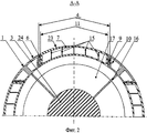
на фиг.2 - разрез А-А на фиг.1;figure 2 is a section aa in figure 1;
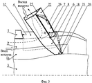
на фиг.3 - схематически изображен продольный разрез устройства поворота вектора тяги потока наружного контура турбореактивного двухконтурного двигателя на режиме реверса тяги;figure 3 - schematically shows a longitudinal section of a device for rotating the thrust vector of the flow of the outer contour of a turbojet bypass engine in thrust reversal mode;
на фиг.4 - схематически изображен продольный разрез устройства поворота вектора тяги отклоняющего под углом к оси двигателя поток наружного контура турбореактивного двухконтурного двигателя на полном режиме ОВТ;figure 4 - schematically shows a longitudinal section of the device of rotation of the thrust vector deflecting at an angle to the axis of the engine the flow of the external circuit of a turbojet bypass engine in full OVT mode;
на фиг.5 - разрез Б-Б на фиг.4;figure 5 is a section bB in figure 4;
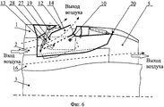
на фиг.6 - схематически изображен продольный разрез устройства поворота вектора тяги турбореактивного двухконтурного двигателя, отклоняющего часть потока воздуха наружного контура на частичном режиме ОВТ и направляющего одновременно другую часть потока наружного контура через сопло для обеспечения режима прямой тяги.6 is a schematic longitudinal sectional view of a thrust vector rotation device of a turbojet bypass engine deflecting a part of the air flow of the external circuit in partial OBH mode and simultaneously directing another part of the external circuit flow through the nozzle to provide a direct thrust mode.
Устройство поворота вектора тяги турбореактивного двухконтурного двигателя, включающего (см. фиг.1, 2) цилиндрическую мотогондолу 1 вентилятора наружного контура 2 и центральное тело 3 газогенератора внутреннего контура, согласно изобретению содержит в задней части мотогондолы 1 по периферии окна 4 и на выходе кольцевое сопло 5. В окнах 4 размещены реверсивные 6 и отклоняющие 7 створки, имеющие форму совкового типа. Реверсивные 6 створки закреплены в задней части каждого окна 4 на поперечных осях 8, закрепленных в мотогондоле 1. Каждая отклоняющая 7 створка шарнирно 9 связана на поперечной оси 10 со своей реверсивной 6 створкой. Кроме того, реверсивные 6 и отклоняющие 7 створки шарнирно соединены со средствами управления их перемещением. Каждая реверсивная 6 створка (см. фиг.2) снабжена окном 11, в котором установлена полая отклоняющая 7 створка. Отклоняющая створка 7 (см. фиг.1, 6) состоит из наружной 12 и внутренней 13 стенок с каналом 14 между ними, в котором установлены перегородки 15, предотвращающие боковое растекание потока на цилиндрических поверхностях. Внешняя поверхность наружной 12 стенки отклоняющей створки 7 на режиме прямой тяги (см. фиг.1) образует часть наружной поверхности мотогондолы 1. Между мотогондолой 1 и центральным телом 3 газогенератора установлены (см. фиг.2, 5) пилоны 16 аэродинамического профиля, образующие отдельные каналы 17 наружного контура 2 двигателя, по которым уплотняются боковые кромки створок 6 на режиме реверсирования тяги или кромок створок 7 при отклонении вектора тяги, а также исключается растекание потока и его влияние на работу соседних каналов 17. Средства управления перемещением реверсивных 6 и отклоняющих 7 створок выполнены (см. фиг.1, 6) в виде отдельных приводов поступательного движения соответственно 18 и 19. Кроме того, каждая реверсивная 6 створка соединена шарнирно 20 задней кромкой 21 с мотогондолой 1 за своим окном 4 через привод 18, а также снабжена в передней части обтекателем 22 в виде полого трехгранного кольцевого сектора. На режимах прямой тяги и отклоняемого вектора тяги (см. фиг.1, 4) наружная грань 23 обтекателя 22 является частью наружной 24 поверхности мотогондолы 1, а две другие грани 25 и 26 являются - соответственно внутренними передней и задней наклонными поверхностями обтекателя 22 реверсивной створки 6. Отклоняющая 7 створка размещена в окне 11 реверсивной 6 створки за обтекателем 22 и связана шарнирно с расположенным в обтекателе 22 отдельным приводом 19. На режиме прямой тяги внутренняя поверхность реверсивной створки 6 и внутренняя поверхность внутренней стенки отклоняющей створки 7 образуют части внутренней поверхности мотогондолы 1 наружного контура 2 двигателя. Канал 14 отклоняющей створки 7 выполнен с косым срезом 28 на входе для стыковки с поверхностью 26 обтекателя 22. Поверхность задней кромки 29 (см. фиг.4, 6) окна 11 реверсивной 6 створки выполнена профилированной из двух сопряженных между собой частей поверхностей 30 наружного и 31 внутреннего соосных торовых секторов. Передняя наклонная поверхность 25 обтекателя 22 створки 6 (см. фиг.3) уплотняется по наклонной поверхности 32 передней кромки окна 4, а задняя наклонная поверхность 26 обтекателя 22 уплотняется передней кромкой 28 канала 14 отклоняющей створки 7. На режиме ОВТ (см. фиг.4, 5) в месте контакта передней кромки 33 внутренней стенки 13 отклоняющей створки 7 с центральным телом 3 газогенератора внутреннего контура возможно наличие щелей 34, через которые часть воздуха контура 2 вытекает наружу через сопло 5. Утечки воздуха могут быть ликвидированы профилированием передней кромки 33 отклоняющей створки 7 по контуру наружной поверхности центрального тела 3.The device for turning the thrust vector of a turbojet bypass engine, including (see FIGS. 1, 2) a
Устройство поворота вектора тяги турбореактивного двухконтурного двигателя не препятствует прохождению воздуха через канал наружного контура 2 на режиме прямой тяги и работает следующим образом.The device for turning the thrust vector of a turbojet bypass engine does not prevent the passage of air through the channel of the
При функционировании устройства на режиме прямой тяги (см. фиг.1, 2) каждый привод 18 втянут и через шарнир 20 на задней кромке 21 устанавливает в окне 4 мотогондолы 1 на поперечной оси 8 реверсивную створку 6 с упором и уплотнением передней наклонной поверхности 25 обтекателя 22 по наклонной поверхности 32 передней кромки окна 4. Каждый привод 19 также втянут, отклоняющая створка 7 размещена на оси 10 с шарнирами 9 в окне 11 реверсивной створки 6 с упором и уплотнением передней косой кромкой 28 по задней наклонной поверхности 26 обтекателя 22. Перемещаясь по наружному контуру 2, воздух через сопло 5 истекает наружу двигателя.When the device is operating in direct traction mode (see Figs. 1, 2), each actuator 18 is retracted and, through a
При функционировании устройства на режиме реверса вектора тяги (см. фиг.3) после подачи команды по заданной программе приводы 18 поворачивают в каждом отдельном окне 4 реверсивные створки 6 до упора их задних кромок 21 в центральное тело 3 газогенератора внутреннего контура. Между внутренней поверхностью наклоненной вперед реверсивной створки 6 и наклонной поверхностью 32 передней кромки отдельного окна 4 в плоскости продольной оси мотогондолы 1 образуется канал для прохода воздуха.When the device is operating in the reverse direction of the thrust vector (see Fig. 3), after giving the command according to the given program, the
При функционировании устройства на полном режиме ОВТ (см. фиг.4, 5) приводы 19 выпускают по заданной команде каждую створку 7 до упора передней кромки 33 внутренней стенки 13 в центральное тело 3 газогенератора внутреннего контура. В отклоняющей створке 7 открывают канал 14. Между внешней поверхностью наружной стенки 12 отклоняющей створки 7 и наклонной поверхностью 26 обтекателя 22 образуют дополнительный канал для прохода воздуха.When the device is operating in full OVT mode (see FIGS. 4, 5), the
При функционировании устройства на частичном режиме ОВТ (см. фиг.6) по команде каждый привод 19 выпускают частично. Створками 7, перемещаемыми приводами 19, частично перекрывают тракт потока газа наружного контура 2 до сопла 5. В отклоняющей створке 7 открывают канал 14 и направляют его выход наружу под острым углом к оси двигателя. Между внешней поверхностью наружной стенки 12 каждой реверсивной створки 6 и наклонной поверхностью 26 обтекателя 22 окна 4 образуют дополнительный канал для прохода воздуха.When the device is operating in partial OBT mode (see Fig. 6), at the command of each drive 19 is partially released. The
Опытные проверки предложенного технического решения подтвердили эффективность работы устройства поворота вектора тяги в мотогондоле наружного контура турбореактивного двухконтурного двигателя для повышения боковой устойчивости, вертикальной и поперечной управляемости самолета на больших углах атаки и малых скоростях полета, снижение потерь в прямом и повернутом потоках воздуха, а также высокую пропускную способность тракта наружного контура двигателя на режимах реверсирования и ОВТ.Experimental checks of the proposed technical solution have confirmed the efficiency of the thrust vector rotation device in the nacelle of the external circuit of a turbojet dual-circuit engine to increase lateral stability, vertical and lateral controllability of the aircraft at large angles of attack and low flight speeds, reduce losses in forward and rotated air flows, as well as high the capacity of the external circuit path of the engine in reverse and OBT modes.
Claims (3)
Priority Applications (1)
| Application Number | Priority Date | Filing Date | Title |
|---|---|---|---|
| RU2010104542/06A RU2425242C1 (en) | 2010-02-11 | 2010-02-11 | Device for turning traction vector of double-flow jet turbine engine |
Applications Claiming Priority (1)
| Application Number | Priority Date | Filing Date | Title |
|---|---|---|---|
| RU2010104542/06A RU2425242C1 (en) | 2010-02-11 | 2010-02-11 | Device for turning traction vector of double-flow jet turbine engine |
Publications (1)
| Publication Number | Publication Date |
|---|---|
| RU2425242C1 true RU2425242C1 (en) | 2011-07-27 |
Family
ID=44753603
Family Applications (1)
| Application Number | Title | Priority Date | Filing Date |
|---|---|---|---|
| RU2010104542/06A RU2425242C1 (en) | 2010-02-11 | 2010-02-11 | Device for turning traction vector of double-flow jet turbine engine |
Country Status (1)
| Country | Link |
|---|---|
| RU (1) | RU2425242C1 (en) |
Cited By (1)
| Publication number | Priority date | Publication date | Assignee | Title |
|---|---|---|---|---|
| EP2987991A1 (en) * | 2014-08-19 | 2016-02-24 | The Boeing Company | Fan nozzle with thrust reversing and variable area function |
Citations (6)
| Publication number | Priority date | Publication date | Assignee | Title |
|---|---|---|---|---|
| FR2146109A1 (en) * | 1971-07-19 | 1973-03-02 | Bruner Georges | |
| US3920203A (en) * | 1974-12-23 | 1975-11-18 | Boeing Co | Thrust control apparatus for obtaining maximum thrust reversal in minimum time upon landing of an aircraft |
| EP0809011A2 (en) * | 1996-05-20 | 1997-11-26 | BOEING NORTH AMERICAN, Inc. | Multiaxis thrust-vectoring for turbo-fan engines |
| RU2134359C1 (en) * | 1996-02-15 | 1999-08-10 | Сосьете Испано-Сюиза | Turbojet engine thrust reverser with flaps connected with front panel in direction of flow |
| RU2145389C1 (en) * | 1996-08-01 | 2000-02-10 | Испано Сюиза | Turbojet-engine draft reverser with bucket-shaped doors (design versions) |
| RU2162537C2 (en) * | 1997-06-05 | 2001-01-27 | Испано-Сюиза Аэрострюктюр | Turbojet-engine thrust reversal unit whose doors form buckets coupled with movable first-in-flow fairing |
-
2010
- 2010-02-11 RU RU2010104542/06A patent/RU2425242C1/en not_active IP Right Cessation
Patent Citations (6)
| Publication number | Priority date | Publication date | Assignee | Title |
|---|---|---|---|---|
| FR2146109A1 (en) * | 1971-07-19 | 1973-03-02 | Bruner Georges | |
| US3920203A (en) * | 1974-12-23 | 1975-11-18 | Boeing Co | Thrust control apparatus for obtaining maximum thrust reversal in minimum time upon landing of an aircraft |
| RU2134359C1 (en) * | 1996-02-15 | 1999-08-10 | Сосьете Испано-Сюиза | Turbojet engine thrust reverser with flaps connected with front panel in direction of flow |
| EP0809011A2 (en) * | 1996-05-20 | 1997-11-26 | BOEING NORTH AMERICAN, Inc. | Multiaxis thrust-vectoring for turbo-fan engines |
| RU2145389C1 (en) * | 1996-08-01 | 2000-02-10 | Испано Сюиза | Turbojet-engine draft reverser with bucket-shaped doors (design versions) |
| RU2162537C2 (en) * | 1997-06-05 | 2001-01-27 | Испано-Сюиза Аэрострюктюр | Turbojet-engine thrust reversal unit whose doors form buckets coupled with movable first-in-flow fairing |
Cited By (3)
| Publication number | Priority date | Publication date | Assignee | Title |
|---|---|---|---|---|
| EP2987991A1 (en) * | 2014-08-19 | 2016-02-24 | The Boeing Company | Fan nozzle with thrust reversing and variable area function |
| US20160053718A1 (en) * | 2014-08-19 | 2016-02-25 | The Boeing Company | Thrust Reverse Variable Area Fan Nozzle |
| US10001080B2 (en) | 2014-08-19 | 2018-06-19 | The Boeing Company | Thrust reverse variable area fan nozzle |
Similar Documents
| Publication | Publication Date | Title |
|---|---|---|
| US9982598B2 (en) | Gas turbine engine variable bleed valve for ice extraction | |
| RU2145390C1 (en) | Turbojet-engine thrust reverser with turning doors and deflecting blades coupled with fixed structure | |
| RU2145389C1 (en) | Turbojet-engine draft reverser with bucket-shaped doors (design versions) | |
| AU2016208300B2 (en) | Folding door thrust reversers for aircraft engines | |
| RU2108941C1 (en) | Power plant for short vertical take-off and landing aircraft | |
| CN105518280B (en) | Integrated thrust reverser and aircraft engine pod equipped with it | |
| EP1399661B1 (en) | Pivot fairing thrust reverser | |
| US4375276A (en) | Variable geometry exhaust nozzle | |
| RU2139434C1 (en) | Thrust reversal unit of turbojet engine with doors provided with deflecting blades | |
| US6845946B2 (en) | Self stowing thrust reverser | |
| US20100126139A1 (en) | Pivoting fan nozzle nacelle | |
| RU2156872C2 (en) | Swinging-door thrust reverser with monitored leakage discharge | |
| US8959889B2 (en) | Method of varying a fan duct nozzle throat area of a gas turbine engine | |
| RU2162537C2 (en) | Turbojet-engine thrust reversal unit whose doors form buckets coupled with movable first-in-flow fairing | |
| CN103717868B (en) | For the thrust reversing apparatus of compact jet pipe | |
| RU2472024C2 (en) | Aircraft nacelle containing thrust reversing device | |
| US4587804A (en) | Device for increasing and deflecting thrust of jet-propulsion engine of V/STOL aircraft | |
| RU2162538C2 (en) | Turbojet-engine thrust-reversal unit with doors forming buckets coupled with movable deflector | |
| JPH02238159A (en) | Gas turbine jet engine | |
| CN103917766A (en) | Thrust reverser device | |
| RU2449151C2 (en) | Car for aircraft and aircraft equipped with such car | |
| RU2136934C1 (en) | Device for reversing thrust of double-flow turbojet engine with doors connected with bearing panel | |
| US6158211A (en) | Turbojet-engine thrust reverser with scoop-doors of adjustable exhaust cross-section | |
| RU2194872C2 (en) | Turbojet engine reaction nozzle with built-in trust reverser mechanism | |
| RU2425242C1 (en) | Device for turning traction vector of double-flow jet turbine engine |
Legal Events
| Date | Code | Title | Description |
|---|---|---|---|
| MM4A | The patent is invalid due to non-payment of fees |
Effective date: 20160212 |