RU2425250C1 - Wind motor on basis of aerodynamic shield - Google Patents
Wind motor on basis of aerodynamic shield Download PDFInfo
- Publication number
- RU2425250C1 RU2425250C1 RU2010104290/06A RU2010104290A RU2425250C1 RU 2425250 C1 RU2425250 C1 RU 2425250C1 RU 2010104290/06 A RU2010104290/06 A RU 2010104290/06A RU 2010104290 A RU2010104290 A RU 2010104290A RU 2425250 C1 RU2425250 C1 RU 2425250C1
- Authority
- RU
- Russia
- Prior art keywords
- air intake
- electric generator
- foundation
- guide ring
- aerodynamic
- Prior art date
Links
Images
Classifications
-
- Y—GENERAL TAGGING OF NEW TECHNOLOGICAL DEVELOPMENTS; GENERAL TAGGING OF CROSS-SECTIONAL TECHNOLOGIES SPANNING OVER SEVERAL SECTIONS OF THE IPC; TECHNICAL SUBJECTS COVERED BY FORMER USPC CROSS-REFERENCE ART COLLECTIONS [XRACs] AND DIGESTS
- Y02—TECHNOLOGIES OR APPLICATIONS FOR MITIGATION OR ADAPTATION AGAINST CLIMATE CHANGE
- Y02E—REDUCTION OF GREENHOUSE GAS [GHG] EMISSIONS, RELATED TO ENERGY GENERATION, TRANSMISSION OR DISTRIBUTION
- Y02E10/00—Energy generation through renewable energy sources
- Y02E10/70—Wind energy
- Y02E10/728—Onshore wind turbines
-
- Y—GENERAL TAGGING OF NEW TECHNOLOGICAL DEVELOPMENTS; GENERAL TAGGING OF CROSS-SECTIONAL TECHNOLOGIES SPANNING OVER SEVERAL SECTIONS OF THE IPC; TECHNICAL SUBJECTS COVERED BY FORMER USPC CROSS-REFERENCE ART COLLECTIONS [XRACs] AND DIGESTS
- Y02—TECHNOLOGIES OR APPLICATIONS FOR MITIGATION OR ADAPTATION AGAINST CLIMATE CHANGE
- Y02E—REDUCTION OF GREENHOUSE GAS [GHG] EMISSIONS, RELATED TO ENERGY GENERATION, TRANSMISSION OR DISTRIBUTION
- Y02E10/00—Energy generation through renewable energy sources
- Y02E10/70—Wind energy
- Y02E10/74—Wind turbines with rotation axis perpendicular to the wind direction
Landscapes
- Wind Motors (AREA)
Abstract
Description
Изобретение относится к ветроэнергетике, а именно к ветродвигателям с направляющими устройствами для воздушного потока, и может быть использовано для автономного энергоснабжения при малоэтажном и коттеджном домостроении, а также для частичного энергоснабжения многоэтажных домов при размещении ветроустановок на крыше здания.The invention relates to wind energy, namely, wind turbines with guiding devices for air flow, and can be used for stand-alone power supply for low-rise and cottage housing, as well as for partial power supply of multi-storey buildings when placing wind turbines on the roof of the building.
Известен ветродвигатель, содержащий вытяжную башню с нижним кольцевым воздухозаборником. Воздухозаборник снабжен вертикальными пластинами, образующими вертикальные каналы и при помощи которых закреплено кольцо серповидного профиля, направляющее воздушный поток на турбину, установленную на вертикальном валу генератора (см. а.с. SU, №1765492, МКИ-5 F03D 3/04).Known wind turbine containing an exhaust tower with a lower annular air intake. The air intake is equipped with vertical plates that form vertical channels and with which a sickle-shaped ring is fixed, directing the air flow to the turbine mounted on the vertical shaft of the generator (see AS SU, No. 1765492, MKI-5 F03D 3/04).
Недостатками известного технического решения являются: сложность конструкции вытяжной башни с воздухозаборником и невозможность выработки электроэнергии при слабых ветрах и при ураганах из-за трудности подъема холодных воздушных масс вверх по башне.The disadvantages of the known technical solutions are: the complexity of the design of the exhaust tower with an air intake and the inability to generate electricity in light winds and during hurricanes due to the difficulty of lifting cold air masses up the tower.
Наиболее близким техническим решением к заявляемому является ветродвигатель, содержащий вытяжную башню-трубу с нижним воздухозаборником, снабженным направляющим кольцом, осевую воздушную турбину, установленную на вертикальном валу генератора (см., патент RU, №2118704, МПК-6 F03D 3/04).The closest technical solution to the claimed one is a wind turbine containing an exhaust tower-pipe with a lower air intake equipped with a guide ring, an axial air turbine mounted on a vertical generator shaft (see, patent RU, No. 21117070, IPC-6 F03D 3/04).
Недостатками известного устройства являются: сложность конструкции, несколько снижена эффективность работы, так как крутящий момент воздушной турбины создается половиной лопастей.The disadvantages of the known device are: design complexity, the efficiency is slightly reduced, since the torque of the air turbine is created by half of the blades.
Техническим результатом заявленного технического решения является повышение коэффициента использования энергии ветра, за счет создания одинаковых условий аэродинамического воздействия на все лопасти вентилятора и упрощение конструкции.The technical result of the claimed technical solution is to increase the utilization of wind energy by creating the same conditions for aerodynamic effects on all fan blades and simplifying the design.
Технический результат достигается тем, что в ветродвигателе, содержащем воздухозаборник с нижним забором воздуха, снабженный направляющим кольцом, осевой многолопастной вентилятор, установленный на вертикальном валу электрогенератора, воздухозаборник дополнительно содержит направляющую решетку, выполненную из пластин, расположенных перпендикулярно друг к другу, а его направляющее кольцо выполнено в виде конусного крыла подъема и расположено по краю решетки, при этом электрогенератор установлен на основании, снабженном амортизаторами, закрепленными на фундаменте и центральной опорной осью, размещенной в сферическом подшипнике, закрепленном в корпусе, установленном на фундаменте.The technical result is achieved in that in a wind turbine containing an air intake with a lower air intake, equipped with a guide ring, an axial multi-blade fan mounted on a vertical shaft of the electric generator, the air intake further comprises a guide grid made of plates arranged perpendicular to each other, and its guide ring made in the form of a conical lift wing and located along the edge of the grill, while the electric generator is mounted on a base equipped with a shock absorber s fixed on the foundation and a central supporting axis located in a spherical bearing mounted in a housing mounted on the foundation.
Выполнение воздухозаборника с направляющей решеткой, выполненной из пластин, расположенных перпендикулярно друг к другу с образованием каналов для прохода воздуха и с направляющим кольцом в виде конусного крыла подъема, размещенным по краю решетки, позволяет получить воздушную подушку, образуемую набегающим потоком воздуха, и создать повышенное давление между конусным крылом подъема и землей (экраном), то есть применить экранный эффект, позволяющий использовать все составляющие полного аэродинамического сопротивления: лобовое сопротивление, подъемную силу, индуктивное сопротивление, что значительно повышает коэффициент использования энергии ветра. Кроме того, существенное повышение давления между экраном и крылом подъема с решеткой позволяет применить высоконапорный многолопастной вентилятор, эффективно работающий на малой скорости ветра, и уменьшить диаметр колеса при сохранении мощности.The implementation of the air intake with a guide grill made of plates perpendicular to each other with the formation of channels for the passage of air and with a guide ring in the form of a conical wing of the lift, located on the edge of the grill, allows you to get an air cushion formed by the oncoming air stream and create increased pressure between the cone wing of the lift and the ground (screen), that is, apply a screen effect that allows you to use all the components of the total aerodynamic drag: ivlenie, lift inductive resistance, which significantly increases the wind energy use factor. In addition, a significant increase in pressure between the screen and the lift wing with the grill allows the use of a high-pressure multi-blade fan that works efficiently at low wind speeds and reduces wheel diameter while maintaining power.
Размещение воздухозаборника на оси электрогенератора, а электрогенератора на основании, снабженном амортизаторами и опорной осью, размещенной в сферическом подшипнике, позволяет, изменяя положение воздухозаборника, изменить угол атаки α и высоту крыла, равномерно распределить давление и создать одинаковые условия аэродинамического воздействия на все лопасти вентилятора, что повышает коэффициент использования энергии ветра.Placing the air intake on the axis of the electric generator, and the electric generator on the base, equipped with shock absorbers and a supporting axis, placed in the spherical bearing, allows changing the air intake position, changing the angle of attack α and wing height, evenly distributing pressure and creating the same aerodynamic effects on all fan blades, which increases the utilization of wind energy.
На фигуре 1 изображен общий вид устройства.The figure 1 shows a General view of the device.
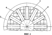
На фигуре 2 изображен вид по стрелке А на фиг.1.Figure 2 shows a view along arrow A in figure 1.
Ветродвигатель содержит воздухозаборник 1 с нижним забором воздуха, содержащий направляющую решетку, по краю которой жестко закреплено направляющее кольцо 2, выполненное в виде конусного крыла подъема, обеспечивающее направление угла атаки α всегда навстречу воздушному потоку. Направляющая решетка, генерирующая подъемную силу, выполнена из пластин 3 и перпендикулярно им расположенных пластин 4. В центре воздухозаборника 1 на вертикальном валу электрогенератора 5 установлен осевой многолопастной вентилятор 6. Электрогенератор 5 закреплен на основании 7, снабженном амортизаторами 8, закрепленными на фундаменте. Основание 7 жестко соединено с опорной осью 9, установленной в сферическом подшипнике 10, закрепленном в корпусе 11, установленном на фундаменте. Подшипник 10 обеспечивает свободное изменение наклона установки, а амортизаторы 8 - плавное изменение наклона и устойчивое рабочие положение установки. Для защиты механизмов от атмосферных осадков ветродвигатель содержит диск защитный 12 в форме перевернутого крыла, установленный над воздухозаборником на опорах, изготовленных, например, из труб. Установка диска защитного 12 создает дополнительное разрежение над вентилятором, ускоряя воздушный поток. Применение опорной оси 9, установленной в сферическом подшипнике 10, позволяет менять угол атаки α и позволяет создать противоштормовую следящую систему.The wind turbine contains an air intake 1 with a lower air intake, containing a guide grid, along the edge of which a guide ring 2 is rigidly fixed, made in the form of a conical wing of the lift, providing the direction of the angle of attack α always towards the air flow. The guiding grid generating the lifting force is made of plates 3 and plates 4 located perpendicular to them. In the center of the air intake 1, an axial multi-blade fan 6 is mounted on the vertical shaft of the electric generator 5. The electric generator 5 is fixed to the base 7, equipped with shock absorbers 8 fixed to the foundation. The base 7 is rigidly connected to the support axis 9 mounted in a spherical bearing 10, mounted in a housing 11 mounted on the foundation. Bearing 10 provides a free change in the inclination of the installation, and shock absorbers 8 provide a smooth change in the inclination and a stable working position of the installation. To protect mechanisms from precipitation, the wind turbine contains a protective disk 12 in the form of an inverted wing mounted above the air intake on supports made, for example, of pipes. The installation of the protective disk 12 creates an additional vacuum above the fan, accelerating the air flow. The use of the support axis 9, mounted in a spherical bearing 10, allows you to change the angle of attack α and allows you to create anti-storm tracking system.
Ветродвигатель работает следующим образом.The wind turbine operates as follows.
Потоки воздуха, соприкасаясь с конусным крылом подъема направляющего кольца 2 воздухозаборника 1, попадают в каналы, образованные пластинами 3 и 4 его направляющей решетки. Конусное крыло подъема обеспечивает направление угла атаки α всегда навстречу воздушному потоку. По каналам направляющей решетки струи воздуха воздействуют на лопасти вентилятора 6 и вращают его, одновременно вращая ротор электрогенератора 5, на валу которого закреплен вентилятор 6. Сферический подшипник, в котором установлена опорная ось и амортизаторы основания, обеспечивают свободное и плавное изменение наклона установки и устойчивое рабочее положение.Air flows in contact with the conical wing of the lifting guide ring 2 of the intake 1, fall into the channels formed by the plates 3 and 4 of its guide lattice. The conical lift wing ensures that the angle of attack α is always directed towards the air flow. Through the channels of the guiding lattice, air jets act on the fan blades 6 and rotate it, while rotating the rotor of the electric generator 5, on the shaft of which the fan 6 is mounted. The spherical bearing, in which the support axis and base shock absorbers are installed, provide a free and smooth change of the installation tilt and stable working position.
Ветродвигатель простой по конструкции, с малым весом и габаритами, использующий низкооборотный вентилятор и позволяющий в паре с ним использовать прогрессивный тихоходный электрогенератор на постоянных магнитах без редуктора, найдет применение в строительстве для автономного энергоснабжения при малоэтажном домостроении, а также для частичного энергоснабжения многоэтажных домов при размещении его на крыше зданий.The wind turbine is simple in design, with a low weight and dimensions, using a low-speed fan and allowing to use a progressive low-speed permanent magnet generator without a reducer, will find application in construction for autonomous power supply for low-rise housing construction, as well as for partial power supply of multi-storey buildings when placing him on the roof of buildings.
Claims (1)
Priority Applications (1)
| Application Number | Priority Date | Filing Date | Title |
|---|---|---|---|
| RU2010104290/06A RU2425250C1 (en) | 2010-02-08 | 2010-02-08 | Wind motor on basis of aerodynamic shield |
Applications Claiming Priority (1)
| Application Number | Priority Date | Filing Date | Title |
|---|---|---|---|
| RU2010104290/06A RU2425250C1 (en) | 2010-02-08 | 2010-02-08 | Wind motor on basis of aerodynamic shield |
Publications (1)
| Publication Number | Publication Date |
|---|---|
| RU2425250C1 true RU2425250C1 (en) | 2011-07-27 |
Family
ID=44753607
Family Applications (1)
| Application Number | Title | Priority Date | Filing Date |
|---|---|---|---|
| RU2010104290/06A RU2425250C1 (en) | 2010-02-08 | 2010-02-08 | Wind motor on basis of aerodynamic shield |
Country Status (1)
| Country | Link |
|---|---|
| RU (1) | RU2425250C1 (en) |
Citations (4)
| Publication number | Priority date | Publication date | Assignee | Title |
|---|---|---|---|---|
| US4935639A (en) * | 1988-08-23 | 1990-06-19 | Yeh Dong An | Revolving power tower |
| GB2275970A (en) * | 1993-03-13 | 1994-09-14 | Kenneth Morgan Davies | Vertical axis wind turbines |
| RU2118704C1 (en) * | 1994-06-20 | 1998-09-10 | Вадим Николаевич Пикуль | Windmill |
| RU2005106463A (en) * | 2005-03-10 | 2006-08-20 | Александр Пантелеймонович Скороход (RU) | METHOD FOR CONVERTING ENERGY OF A FLUID AND A MOTOR IMPLEMENTING A METHOD |
-
2010
- 2010-02-08 RU RU2010104290/06A patent/RU2425250C1/en not_active IP Right Cessation
Patent Citations (4)
| Publication number | Priority date | Publication date | Assignee | Title |
|---|---|---|---|---|
| US4935639A (en) * | 1988-08-23 | 1990-06-19 | Yeh Dong An | Revolving power tower |
| GB2275970A (en) * | 1993-03-13 | 1994-09-14 | Kenneth Morgan Davies | Vertical axis wind turbines |
| RU2118704C1 (en) * | 1994-06-20 | 1998-09-10 | Вадим Николаевич Пикуль | Windmill |
| RU2005106463A (en) * | 2005-03-10 | 2006-08-20 | Александр Пантелеймонович Скороход (RU) | METHOD FOR CONVERTING ENERGY OF A FLUID AND A MOTOR IMPLEMENTING A METHOD |
Similar Documents
| Publication | Publication Date | Title |
|---|---|---|
| CN1249340C (en) | Wind-gathering wind power generation method and equipment | |
| US11236724B2 (en) | Vertical axis wind turbine | |
| WO2010098656A2 (en) | Wind, solar and rain harvester | |
| WO2016023351A1 (en) | All-directional flow-guide shaftless wind-driven generator | |
| CN103939291B (en) | Height wind speed compatible type Wind turbines | |
| US20160169193A1 (en) | Compact wind power generation system | |
| CN102667143A (en) | Method and solar-powered wind plant for producing electric power | |
| US11156204B2 (en) | Wind turbine | |
| EA023719B1 (en) | Wind-driven plant for power generation and method for power generation using wind-driven plant | |
| JP2008506877A5 (en) | ||
| RU2531478C2 (en) | Wind turbine | |
| CN101532471B (en) | Magnetic suspension vertical turbine wind generator | |
| CN103953497A (en) | Vortex type power mechanism | |
| CN203130368U (en) | Fixing wind scooper type magnetic levitation wind driven generator | |
| CN102913393A (en) | compressed gas turbine wind turbine | |
| CN101749179A (en) | Rectification speed increasing tower used for vertical axis wind turbine | |
| RU2425250C1 (en) | Wind motor on basis of aerodynamic shield | |
| WO2022149563A1 (en) | Wind power generator installable on moving body | |
| US20130058758A1 (en) | Wind turbine installed on the top floor of a residential building, particularly in an urban area | |
| CN202215426U (en) | Wind generating set with gradually-expanding wind gathering cover | |
| CN202510288U (en) | Wind power fan with multiple sets of wind rotors | |
| RU2426004C1 (en) | Wind-electric plant for multi-storey buildings and structures | |
| CN104775989A (en) | Semi-floating shock-absorption type vertical-axis wind turbine generator set | |
| JP2015166562A (en) | Vertical axis drag type wind turbine capable of preventing its overspeed under strong wind and wind power generator | |
| JP2012251534A5 (en) |
Legal Events
| Date | Code | Title | Description |
|---|---|---|---|
| MM4A | The patent is invalid due to non-payment of fees |
Effective date: 20140209 |