RU2425271C1 - Seal with zigzag-shaped pins - Google Patents
Seal with zigzag-shaped pins Download PDFInfo
- Publication number
- RU2425271C1 RU2425271C1 RU2009141810/06A RU2009141810A RU2425271C1 RU 2425271 C1 RU2425271 C1 RU 2425271C1 RU 2009141810/06 A RU2009141810/06 A RU 2009141810/06A RU 2009141810 A RU2009141810 A RU 2009141810A RU 2425271 C1 RU2425271 C1 RU 2425271C1
- Authority
- RU
- Russia
- Prior art keywords
- fingers
- annular
- seal
- pins
- slots
- Prior art date
Links
- 230000013011 mating Effects 0.000 abstract description 2
- 239000000126 substance Substances 0.000 abstract 1
- 230000002441 reversible effect Effects 0.000 description 3
- 238000007789 sealing Methods 0.000 description 3
- 238000000034 method Methods 0.000 description 2
- 230000006835 compression Effects 0.000 description 1
- 238000007906 compression Methods 0.000 description 1
- 238000010276 construction Methods 0.000 description 1
- 239000012634 fragment Substances 0.000 description 1
- 239000000463 material Substances 0.000 description 1
Images
Landscapes
- Adornments (AREA)
- Gasket Seals (AREA)
- Sealing Devices (AREA)
Abstract
Description
Изобретение относится к области турбо- и двигателестроения и может быть использовано в конструкциях газотурбинных двигателей и паровых турбин для уплотнения радиальных зазоров.The invention relates to the field of turbo and engine building and can be used in the construction of gas turbine engines and steam turbines for sealing radial clearances.
Наличие радиальных зазоров в проточной части газотурбинной техники необходимо для исключения "заклинивания" ротора и статора во время работы. Таким образом, возникает необходимость установки уплотнений в проточной части, которые позволяют минимизировать перетоки рабочей среды (газа, пара, масла) через кольцевую щель между ротором и статором (между рабочими лопатками и сопловым аппаратом, валом и корпусом и т.п.).The presence of radial clearances in the flowing part of gas turbine equipment is necessary to eliminate the "jamming" of the rotor and stator during operation. Thus, there is a need to install seals in the flow part, which allow to minimize the flow of the working medium (gas, steam, oil) through the annular gap between the rotor and stator (between the working blades and the nozzle apparatus, shaft and housing, etc.).
Одними из наиболее эффективных классов уплотнений радиальных зазоров являются пальчиковые уплотнения. Общим недостатком известных конструкций пальчиковых уплотнений является то, что они имеют пальчики с относительно простой конструктивной формой - в виде консольно закрепленного стержня малой кривизны. Как следствие, пальчики имеют недостаточно высокую гибкость, чтобы компенсировать значительные по величине отклонения ротора. Это не позволяет использовать их при больших отклонениях ротора.One of the most effective classes of radial clearance seals is finger seals. A common disadvantage of the known designs of finger seals is that they have fingers with a relatively simple structural form - in the form of a cantilever fixed rod of small curvature. As a result, the fingers are not flexible enough to compensate for significant rotor deflections. This does not allow them to be used for large rotor deviations.
Известно реверсивное пальчиковое уплотнение, содержащее, по крайней мере, две пары сложенных в стопку тонких кольцевых деталей, каждая из которых содержит кольцевой массив радиально и тангенциально вступающих пальчиков, между которыми имеются щели. Кольцевые детали каждой из пар расположены таким образом, что пальчики одной кольцевой детали перекрывают щели в другой. Причем пальчики кольцевых деталей одной из пар расположены под углом в направлении по часовой стрелке, а пальчики кольцевых деталей другой пары - в направлении против часовой стрелки [US 5031922, F16J 15/447, 16.07.1991].A reversible finger seal is known, containing at least two pairs of thin ring parts folded into a stack, each of which contains an annular array of radially and tangentially entering fingers, between which there are gaps. The ring parts of each of the pairs are arranged so that the fingers of one ring part overlap the slots in the other. Moreover, the fingers of the ring parts of one of the pairs are located at an angle in the clockwise direction, and the fingers of the ring parts of the other pair are in the counterclockwise direction [US 5031922, F16J 15/447, 07/16/1991].
Недостатком этого уплотнения является то, что оно не может компенсировать значительные отклонения ротора вследствие тепловых и механических деформаций, т.к. форма пальчиков не является оптимальной с точки зрения упругих свойств данной конструкции. Недостаточная гибкость пальчиков приводит к тому, что в процессе эксплуатации из-за чрезмерного обжатия уплотняемой поверхности возможно появление прижогов на соприкасающихся поверхностях пальчиков и поверхности ротора, снижение мощности на валу двигателя, повышение износа контактирующих пар.The disadvantage of this seal is that it cannot compensate for significant deviations of the rotor due to thermal and mechanical deformation, because the shape of the fingers is not optimal in terms of the elastic properties of this design. The insufficient flexibility of the fingers leads to the fact that during operation due to excessive compression of the sealing surface, burns may occur on the contacting surfaces of the fingers and the rotor surface, a decrease in power on the motor shaft, and increased wear of the contacting pairs.
Наиболее близким по технической сущности к предлагаемому является пальчиковое уплотнение, содержащее две примыкающие друг к другу кольцевые детали, каждая из которых содержит равномерно расположенные по окружности пальчики, образованные путем выполнения щелей в кольцевых деталях, по меньшей мере, одна из которых имеет выступающие площадки, выполненные за одно целое с соответствующими пальчиками, причем кольцевые детали установлены таким образом, чтобы пальчики каждой кольцевой детали перекрывали щели примыкающей к ней другой кольцевой детали. Все пальчики имеют одинаковую толщину и отделены друг от друга одинаковыми щелями. Пальчики имеют кривизну, определяемую экспоненциальным выражением [US 5755445, F16J 15/447, 26.05.1998].The closest in technical essence to the proposed one is a finger seal containing two adjacent ring parts, each of which contains fingers evenly spaced around the circumference, formed by making slits in the ring parts, at least one of which has protruding pads made integrally with the corresponding fingers, and the annular parts are mounted so that the fingers of each annular part overlap the slots adjacent to the other ring Second part. All fingers have the same thickness and are separated from each other by the same slots. Fingers have a curvature defined by an exponential expression [US 5755445, F16J 15/447, 05.26.1998].
Недостатком этого изобретения, как и предыдущего, является недостаточно высокая гибкость пальчиков, что не позволяет его использовать при значительных отклонениях ротора в процессе эксплуатации. Еще одним недостатком данного уплотнения является то, что из-за одностороннего наклона пальчиков (по или против часовой стрелки) оно не может быть использовано для эффективного уплотнения роторов, имеющих возможность реверсивного движения.The disadvantage of this invention, as well as the previous one, is the insufficiently high flexibility of the fingers, which does not allow it to be used with significant deviations of the rotor during operation. Another disadvantage of this seal is that due to the one-sided tilt of the fingers (clockwise or counterclockwise), it cannot be used for efficient sealing of rotors with the possibility of reverse movement.
Технический результат заявленного изобретения - повышение эффективности пальчикового уплотнения при значительных отклонениях ротора в процессе эксплуатации и повышение надежности уплотнения за счет улучшения гибкости пальчиков.The technical result of the claimed invention is to increase the efficiency of the finger seal with significant deviations of the rotor during operation and increase the reliability of the seal by improving the flexibility of the fingers.
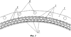
Указанный технический результат достигается тем, что пальчиковое уплотнение содержит примыкающие друг к другу кольцевые детали, каждая из которых содержит равномерно расположенные по окружности пальчики, образованные путем выполнения щелей в кольцевых деталях, по меньшей мере, одна из которых имеет выступающие площадки, выполненные за одно целое с соответствующими пальчиками, причем кольцевые детали установлены таким образом, чтобы пальчики каждой кольцевой детали перекрывали щели примыкающей к ней другой кольцевой детали, щели и образованные между ними пальчики имеют ответную друг другу зигзагообразную форму.The indicated technical result is achieved in that the finger seal contains annular parts adjacent to each other, each of which contains fingers evenly spaced around the circumference, formed by making slits in the annular parts, at least one of which has protruding pads made in one piece with the corresponding fingers, and the annular parts are mounted so that the fingers of each annular part overlap the slots of the adjacent other annular part, the slit and azovannye fingers therebetween are reciprocal to each other zigzag shape.
Кроме того, ширина пальчиков в любом сечении, перпендикулярном их оси, меньше толщины кольцевой детали.In addition, the width of the fingers in any section perpendicular to their axis is less than the thickness of the annular part.
Выполнение кольцевых деталей со щелями и образованных между ними пальчиками зигзагообразной формы позволяет повысить гибкость пальчиков, уменьшить износ и исключить повреждение контактирующих пар, что, соответственно, повышает эффективность и надежность пальчикового уплотнения.The implementation of the ring parts with slots and the fingers formed in a zigzag shape between them allows you to increase the flexibility of the fingers, reduce wear and eliminate damage to the contacting pairs, which, accordingly, increases the efficiency and reliability of the finger seal.
Предлагаемая конструкция пальчикового уплотнения объясняется приведенными схематичными чертежами.The proposed design of the finger seal is explained in the schematic drawings.
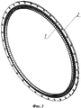
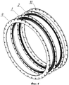
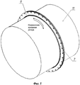
На фиг.1 схематически изображен изометрический вид пальчикового уплотнения; на фиг.2 - увеличенный изометрический вид пальчикового уплотнения с сечением в осевой плоскости, на фиг.3 - увеличенный фрагмент кольцевой детали пальчикового уплотнения в радиальной плоскости; на фиг.4 - изометрический вид составных деталей пальчикового уплотнения; на фиг.5 - изометрический вид пальчикового уплотнения и уплотняемого вала.Figure 1 schematically shows an isometric view of a finger seal; figure 2 is an enlarged isometric view of the finger seal with a cross section in the axial plane, figure 3 is an enlarged fragment of the annular part of the finger seal in the radial plane; figure 4 is an isometric view of the components of a finger seal; figure 5 is an isometric view of the finger seal and the shaft being sealed.
Пальчиковое уплотнение состоит из двух примыкающих друг с другу кольцевых деталей 1 и 2 (фиг.1), каждая из которых содержит равномерно расположенные по окружности зигзагообразные пальчики 3 и 4 (фиг.2, 3), между которыми имеются ответные им зигзагообразные щели 5 и 6. На кольцевой детали 1, расположенной со стороны полости низкого давления, имеются выступающие площадки 7, выполненные за одно целое с соответствующими пальчиками 3. Кольцевые детали 1 и 2 ориентированы по сквозным отверстиям 8 (выполненными в кольцевых деталях 1 и 2) и спозиционированы (установлены) друг относительно друга таким образом, что пальчики каждой кольцевой детали перекрывают щели между пальчиками в другой кольцевой детали, причем ширина пальчиков больше ширины перекрываемых ими щелей.The finger seal consists of two
В расширенном варианте конструкции пальчикового уплотнения кольцевые детали 1 и 2 могут быть прижаты со стороны полостей низкого и высокого давления кольцевыми крышками 9, 10 (фиг.4) для повышения жесткости конструкции в осевом направлении.In an expanded embodiment of the design of the finger seal, the
Пакет из кольцевых деталей 1, 2 и кольцевых крышек 9, 10 может быть закреплен с помощью соединительных элементов, например заклепок (на чертежах не показаны), расположенных в сквозных отверстиях 8 по окружности пальчикового уплотнения.A package of
Для повышения механической устойчивости пальчиков их ширина в любом сечении, перпендикулярном оси пальчика, должна быть меньше толщины кольцевой детали.To increase the mechanical stability of the fingers, their width in any section perpendicular to the axis of the finger should be less than the thickness of the annular part.
Приведенное описание пальчикового уплотнения составлено для случая использования двух кольцевых деталей с пальчиками, но не исключает применение и большего числа кольцевых деталей.The above description of the finger seal is made for the case of using two ring parts with fingers, but does not exclude the use of a larger number of ring parts.
Пальчиковое уплотнение работает следующим образом.Finger seal works as follows.
Между деталью 11 ротора (фиг.5) и пальчиками 3 и 4 устанавливается минимально допустимый зазор, который выбирается из условия отсутствия задевания деталью 11 ротора выступающих площадок 7 при нормальном режиме работы (в зависимости от габаритов ротора и условий работы зазор составляет 0,05…0,2 мм).Between the rotor part 11 (Fig. 5) and the
В процессе пуска и изменения режима работы двигателя, когда возникают значительные отклонения детали ротора 11, происходит контакт пальчиков 3 и 4 с поверхностью детали ротора 11. При этом пальчики 3 и 4 деформируются, что предотвращает "заклинивание" деталей ротора и статора.In the process of starting and changing the engine operating mode, when significant deviations of the
В отличие от пальчиковых уплотнений с простой формой пальчиков предлагаемая конструкция имеет повышенные упругие свойства, что позволяет использовать данное уплотнение при значительных колебаниях ротора без ущерба работоспособности конструкции.Unlike finger seals with a simple finger shape, the proposed design has increased elastic properties, which allows the use of this seal with significant rotor vibrations without compromising the performance of the structure.
Еще одним преимуществом предлагаемой конструкции является то, что выступающие площадки благодаря зигзагообразной форме пальчиков отклоняются преимущественно в радиальном направлении, что позволяет использовать данную конструкцию для уплотнения роторов, имеющих возможность реверсивного движения (фиг.5).Another advantage of the proposed design is that the protruding platforms due to the zigzag shape of the fingers deviate mainly in the radial direction, which allows you to use this design to seal rotors with the possibility of reverse movement (figure 5).
Для получения зигзагообразных щелей пальчиковых уплотнений наиболее рационально применение импульсной электрохимической обработки, основные преимущества которой следующие: отсутствие износа электрода-инструмента во время обработки, отсутствие термически измененного слоя, острых кромок и заусенцев на обработанной поверхности, возможность одновременной обработки всех межпальчиковых пазов специальным электродом-инструментом со множеством зигзагообразных выступов, достаточно низкая погрешность обработки (не более 20…30 мкм), хорошие показатели по шероховатости (Ra 0,2…1,25 мкм - в зависимости от материала).To obtain zigzag gaps of finger seals, the most rational is the use of pulsed electrochemical processing, the main advantages of which are the following: no wear of the electrode tool during processing, no thermally changed layer, sharp edges and burrs on the treated surface, the ability to simultaneously process all inter-finger grooves with a special electrode tool with many zigzag protrusions, fairly low processing error (not more than 20 ... 30 microns), good indicators of roughness (R a 0,2 ... 1,25 mm - depending on the material).
Таким образом, предложенное изобретение благодаря повышенной гибкости зигзагообразных пальчиков позволяет использовать его при значительных отклонениях ротора в процессе эксплуатации, а также повышает надежность уплотнения за счет уменьшения износа и вероятности повреждения контактирующих пар.Thus, the proposed invention due to the increased flexibility of the zigzag fingers allows you to use it with significant rotor deviations during operation, and also increases the reliability of the seal by reducing wear and the likelihood of damage to the contacting pairs.
Claims (1)
Priority Applications (1)
| Application Number | Priority Date | Filing Date | Title |
|---|---|---|---|
| RU2009141810/06A RU2425271C1 (en) | 2009-11-13 | 2009-11-13 | Seal with zigzag-shaped pins |
Applications Claiming Priority (1)
| Application Number | Priority Date | Filing Date | Title |
|---|---|---|---|
| RU2009141810/06A RU2425271C1 (en) | 2009-11-13 | 2009-11-13 | Seal with zigzag-shaped pins |
Publications (2)
| Publication Number | Publication Date |
|---|---|
| RU2009141810A RU2009141810A (en) | 2011-05-20 |
| RU2425271C1 true RU2425271C1 (en) | 2011-07-27 |
Family
ID=44733418
Family Applications (1)
| Application Number | Title | Priority Date | Filing Date |
|---|---|---|---|
| RU2009141810/06A RU2425271C1 (en) | 2009-11-13 | 2009-11-13 | Seal with zigzag-shaped pins |
Country Status (1)
| Country | Link |
|---|---|
| RU (1) | RU2425271C1 (en) |
Citations (4)
| Publication number | Priority date | Publication date | Assignee | Title |
|---|---|---|---|---|
| US5096376A (en) * | 1990-08-29 | 1992-03-17 | General Electric Company | Low windage corrugated seal facing strip |
| US5558341A (en) * | 1995-01-11 | 1996-09-24 | Stein Seal Company | Seal for sealing an incompressible fluid between a relatively stationary seal and a movable member |
| US5755445A (en) * | 1996-08-23 | 1998-05-26 | Alliedsignal Inc. | Noncontacting finger seal with hydrodynamic foot portion |
| RU2153112C2 (en) * | 1998-08-25 | 2000-07-20 | Акционерное общество открытого типа "Ленинградский Металлический завод" | Honeycomb seal for turbomachine radial clearance |
-
2009
- 2009-11-13 RU RU2009141810/06A patent/RU2425271C1/en active
Patent Citations (4)
| Publication number | Priority date | Publication date | Assignee | Title |
|---|---|---|---|---|
| US5096376A (en) * | 1990-08-29 | 1992-03-17 | General Electric Company | Low windage corrugated seal facing strip |
| US5558341A (en) * | 1995-01-11 | 1996-09-24 | Stein Seal Company | Seal for sealing an incompressible fluid between a relatively stationary seal and a movable member |
| US5755445A (en) * | 1996-08-23 | 1998-05-26 | Alliedsignal Inc. | Noncontacting finger seal with hydrodynamic foot portion |
| RU2153112C2 (en) * | 1998-08-25 | 2000-07-20 | Акционерное общество открытого типа "Ленинградский Металлический завод" | Honeycomb seal for turbomachine radial clearance |
Non-Patent Citations (1)
| Title |
|---|
| U 2355892 C2, 20.05.2009. * |
Also Published As
| Publication number | Publication date |
|---|---|
| RU2009141810A (en) | 2011-05-20 |
Similar Documents
| Publication | Publication Date | Title |
|---|---|---|
| CN1215251C (en) | Seals for fluid turbines | |
| US8066475B2 (en) | Labyrinth compression seal and turbine incorporating the same | |
| JP2003106105A (en) | Shaft sealing mechanism and turbine | |
| JP6088634B2 (en) | Labyrinth seal for turbine | |
| CN1211668A (en) | Anti-lag brush seal | |
| CN101153545A (en) | Stationary-rotating assembly and method with surface features that enhance confining fluid flow | |
| JPH11230361A (en) | Brush seal | |
| CN1573023A (en) | Shaft seal mechanism | |
| EP2960558B1 (en) | Shaft seal device and rotary machine | |
| JPH1054205A (en) | Gas turbine subassembly | |
| CN1475656A (en) | End face clearance seal and its improvement of the static sealing strip section at the top of the turbine blade | |
| JP2017106395A (en) | Seal structure and turbine | |
| KR101838837B1 (en) | Shroud, moving blade element, and rotary machine | |
| RU2607195C2 (en) | Sealing assembly and rotary machine | |
| CN205823709U (en) | Compressor seal part and combustion gas turbine systems for turbine | |
| US10228061B2 (en) | Seal arrangement | |
| RU2425271C1 (en) | Seal with zigzag-shaped pins | |
| US20160290511A1 (en) | Shaft seal and method for producing same | |
| JP2005180278A (en) | SEALING DEVICE AND STEAM TURBINE HAVING THE SAME | |
| US20160281520A1 (en) | Shaft sealing device, rotating machine, and method for manufacturing shaft sealing device | |
| JP2017061897A (en) | Labyrinth seal device | |
| RU2416752C1 (en) | Cellular structure finger-type seal | |
| CN100370113C (en) | Turbine moving blade shroud structure | |
| JP6382115B2 (en) | Shroud for pretwisted wing | |
| JP4031699B2 (en) | Shaft seal mechanism and turbine |
Legal Events
| Date | Code | Title | Description |
|---|---|---|---|
| PD4A | Correction of name of patent owner | ||
| PC41 | Official registration of the transfer of exclusive right |
Effective date: 20210329 |