RU2425281C1 - Vertical steam-water heat exchanger - Google Patents
Vertical steam-water heat exchanger Download PDFInfo
- Publication number
- RU2425281C1 RU2425281C1 RU2010105452/06A RU2010105452A RU2425281C1 RU 2425281 C1 RU2425281 C1 RU 2425281C1 RU 2010105452/06 A RU2010105452/06 A RU 2010105452/06A RU 2010105452 A RU2010105452 A RU 2010105452A RU 2425281 C1 RU2425281 C1 RU 2425281C1
- Authority
- RU
- Russia
- Prior art keywords
- chamber
- water
- compartment
- pipe
- outlet
- Prior art date
Links
- XLYOFNOQVPJJNP-UHFFFAOYSA-N water Substances O XLYOFNOQVPJJNP-UHFFFAOYSA-N 0.000 title claims abstract description 98
- 238000005192 partition Methods 0.000 claims abstract description 10
- 238000000034 method Methods 0.000 abstract description 3
- 239000000126 substance Substances 0.000 abstract 1
- 230000005494 condensation Effects 0.000 description 5
- 238000009833 condensation Methods 0.000 description 5
- 238000010438 heat treatment Methods 0.000 description 3
- 230000006866 deterioration Effects 0.000 description 1
- 230000007717 exclusion Effects 0.000 description 1
- 230000001172 regenerating effect Effects 0.000 description 1
- 230000001105 regulatory effect Effects 0.000 description 1
Images
Landscapes
- Heat-Exchange Devices With Radiators And Conduit Assemblies (AREA)
Abstract
Description
Изобретение относится к области энергетики и может быть использовано в вертикальных пароводяных теплообменных аппаратах систем теплоснабжения, подогревателях регенеративных систем паровых турбин, предназначенных для подогрева воды за счет тепла, выделяемого при конденсации пара на трубах поверхности теплообмена.The invention relates to the field of energy and can be used in vertical steam-water heat exchangers of heat supply systems, heaters of regenerative systems of steam turbines, designed to heat water due to the heat generated during condensation of steam on the pipes of the heat exchange surface.
Известен вертикальный подогреватель, включающий корпус с патрубком подвода пара и отвода его конденсата, трубную систему из прямых труб, нижнюю распределительную водяную камеру с перегородкой и патрубком входа и выхода нагреваемой воды, верхнюю поворотную (плавающую) камеру (Подогреватель ПН - 3000-25-16-III А. Отраслевой каталог «Теплообменное оборудование паротурбинных установок», 20-89-09, М., 1989, часть I, стр.86, рис.74).Known vertical heater, comprising a housing with a pipe for supplying steam and its condensate, a pipe system of straight pipes, a lower distribution water chamber with a baffle and a pipe for the input and output of heated water, the upper rotary (floating) chamber (heater PN - 3000-25-16 -III A. The industry catalog "Heat exchange equipment of steam turbine plants", 20-89-09, M., 1989, part I, p. 86, Fig. 74).
Недостатком известного двухходового по нагреваемой воде подогревателя является движение воды в трубах второго хода сверху (из поворотной камеры), вниз (в распределительную водяную камеру), что приводит к увеличению средней толщины пленки конденсата и к ухудшению теплообменника по сравнению с движением нагреваемой воды снизу вверх. Для труб второго хода при движении воды сверху вниз в этом подогревателе минимальная температура нагреваемой воды будет на входе в трубный пучок (верх трубного пучка) и максимальная на выходе (низ трубного пучка). Поэтому на любом вертикальном отрезке или на всей длине труб второго хода максимальная конденсация пара будет наблюдаться на верхнем участке труб и минимальная конденсация на нижних участках труб. При таком направлении движения нагреваемой воды в трубах толщина пленки конденсата по длине труб поверхности теплообмена будет увеличиваться сверху вниз, и средняя толщина пленки конденсата на трубах будет больше по сравнению с движением воды снизу вверх, и условия теплообмена будут хуже при всех прочих равных условиях.A disadvantage of the known two-way heater for heated water is the movement of water in the second stroke pipes from above (from the rotary chamber), down (to the distribution water chamber), which leads to an increase in the average thickness of the condensate film and to a deterioration of the heat exchanger compared to the movement of heated water from the bottom up. For second-stroke pipes, when water moves from top to bottom in this heater, the minimum temperature of the heated water will be at the entrance to the tube bundle (top of the tube bundle) and maximum at the outlet (bottom of the tube bundle). Therefore, on any vertical segment or along the entire length of the second-stroke pipes, the maximum vapor condensation will be observed in the upper pipe section and the minimum condensation in the lower pipe sections. With this direction of movement of the heated water in the pipes, the thickness of the condensate film along the length of the pipes of the heat exchange surface will increase from top to bottom, and the average thickness of the condensate film on the pipes will be larger than the movement of water from bottom to top, and the heat transfer conditions will be worse, all other things being equal.
Известен вертикальный подогреватель, содержащий корпус с патрубками подвода пара и отвода его конденсата, верхнюю распределительную камеру с внутренними перегородками и патрубками входа и выхода нагреваемой воды, нижнюю поворотную водяную камеру с перегородками, трубную систему с установленными внутри нее подъемными (перепускными) трубами, соединяющими входные отсеки плавающей водяной камеры с выходными отсеками распределительной водяной камеры (SU 1435888, МПК: F22D 1/32, опубликовано 07.11.88).A vertical heater is known, comprising a housing with steam supply and condensate branch pipes, an upper distribution chamber with internal partitions and heated water inlet and outlet pipes, a lower rotary water chamber with partitions, a pipe system with lifting (bypass) pipes installed inside it connecting the input compartments of the floating water chamber with the output compartments of the distribution water chamber (SU 1435888, IPC: F22D 1/32, published 07.11.88).
По совокупности признаков это известное техническое решение является наиболее близким к заявляемому и принято за прототип.By the totality of the features, this known technical solution is the closest to the claimed one and is taken as a prototype.
Недостатком известного подогревателя, принятого за прототип, является размещение перепускных труб, соединяющих отсеки распределительной и плавающей водяной камеры внутри трубной системы, что увеличивает диаметры водяных камер, корпуса, трубных досок и массу подогревателя. Отсутствует возможность регулирования тепловой нагрузки и температуры нагреваемой воды на выходе за счет исключения из работы части поверхности теплообмена при сохранении величины расхода нагреваемой воды и давления греющего пара.A disadvantage of the known heater, adopted for the prototype, is the placement of bypass pipes connecting the compartments of the distribution and floating water chambers inside the pipe system, which increases the diameters of the water chambers, casing, tube boards and the mass of the heater. There is no possibility of regulating the heat load and the temperature of the heated water at the outlet due to the exclusion of part of the heat transfer surface from operation while maintaining the flow rate of the heated water and the pressure of the heating steam.
Заявляемое техническое решение позволяет повысить эффективность процесса теплообмена за счет уменьшения средней толщины пленки конденсата на всех трубах поверхности теплообмена, а также осуществить регулирование тепловой нагрузки и температуры нагреваемой воды на выходе из теплообменника за счет исключения из работы части поверхности теплообмена. При движении нагреваемой воды снизу вверх (первый ход воды предлагаемого подогревателя типа ПН - 3000) максимальная конденсация пара, а следовательно, и толщина пленки наблюдается на нижних участках труб, где температура нагреваемой воды минимальна. Это максимальное количество сконденсировавшегося пара не участвует в увеличении толщины пленки верхних участков, и поэтому средняя толщина пленки на участке труб будет меньше, а условия теплообмена лучше по сравнению с движением нагреваемой воды сверху вниз.The claimed technical solution allows to increase the efficiency of the heat transfer process by reducing the average thickness of the condensate film on all pipes of the heat transfer surface, and also to regulate the heat load and the temperature of the heated water at the outlet of the heat exchanger by eliminating part of the heat transfer surface from operation. When the heated water moves from the bottom up (the first water course of the proposed heater type PN - 3000), the maximum condensation of the vapor, and therefore the film thickness, is observed in the lower sections of the pipes, where the temperature of the heated water is minimal. This maximum amount of condensed vapor does not participate in an increase in the film thickness of the upper sections, and therefore the average film thickness in the pipe section will be less, and the heat transfer conditions are better than the movement of heated water from top to bottom.
Предложен вертикальный пароводяной теплообменник, включающий корпус с патрубками подвода пара и выхода его конденсата, трубную систему из пучков прямых труб поверхности теплообмена, нижнюю распределительную водяную камеру с перегородками, делящими камеру на отсеки, патрубки входа и выхода нагреваемой воды, верхнюю поворотную водяную камеру с перегородками, делящими камеру на отсеки, отводящий трубопровод, при этом патрубки входа нагреваемой воды расположены на каждом отсеке нижней распределительной водяной камеры, а патрубки выхода нагреваемой воды - на каждом отсеке поворотной камеры, причем патрубки выхода воды из первого, второго, третьего отсека поворотной камеры соединены внешними трубопроводами с задвижками соответственно со вторым, третьим и четвертым отсеками распределительной водяной камеры и отводящим трубопроводом с задвижкой, а последний отсек поворотной камеры соединен внешним трубопроводом с задвижкой только с отводящим трубопроводом.A vertical steam-water heat exchanger is proposed, including a housing with steam supply and condensate outlet pipes, a pipe system of straight tube bundles of heat exchange surface, a lower distribution water chamber with partitions dividing the chamber into compartments, heated water inlet and outlet pipes, an upper rotary water chamber with partitions dividing the chamber into compartments, the outlet pipe, while the nozzles of the inlet of the heated water are located on each compartment of the lower distribution water chamber, and the nozzles of the outlet heated water - on each compartment of the rotary chamber, and the water outlet pipes from the first, second, third compartment of the rotary chamber are connected by external pipelines with valves, respectively, to the second, third and fourth compartments of the distribution water chamber and the discharge pipe with a valve, and the last compartment of the rotary chamber is connected external pipeline with a gate valve only with a discharge pipe.
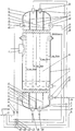
Изобретение иллюстрируется чертежом, где изображен четырехходовой по нагреваемой воде вертикальный пароводяной теплообменник, продольный разрез.The invention is illustrated in the drawing, which shows a four-way vertical steam-water heat exchanger, longitudinal section, along heated water.
Вертикальный пароводяной теплообменник включает корпус 1 с патрубками подвода пара 2 и выхода его конденсата 3, трубную систему 4 из пучков прямых труб поверхности теплообмена, нижнюю распределительную водяную камеру 5 с перегородками 6, делящими камеру 5 на отсеки 7, 8, 9, 10, верхнюю поворотную водяную камеру 11 с перегородками 12, делящими камеру 11 на отсеки 13, 14, 15, 16, отводящий трубопровод 17. Патрубки входа нагреваемой воды 18, 19, 20, 21 расположены на каждом отсеке 7, 8, 9, 10 нижней распределительной водяной камеры 5. Патрубки выхода нагреваемой воды 22, 23, 24, 25 расположены на каждом отсеке 13, 14, 15, 16 поворотной водяной камеры 11. Патрубок выхода нагреваемой воды 22 из отсека 13 поворотной водяной камеры 11 соединен посредством внешнего трубопровода 26 через задвижку 30 и патрубок 19 с отсеком 8 нижней распределительной водяной камеры 5 или с отводящим трубопроводом 17 через задвижку 31. Патрубок выхода нагреваемой воды 23 из отсека 14 поворотной водяной камеры 11 соединен посредством внешнего трубопровода 27 через задвижку 32 и патрубок 20 с отсеком 9 нижней распределительной водяной камеры 5, или через задвижку 33 с отводящим трубопроводом 17. Патрубок выхода нагреваемой воды 24 из отсека 15 поворотной водяной камеры 11 соединен посредством внешнего трубопровода 28 через задвижку 34 и патрубок 21 с отсеком 10 нижней распределительной водяной камеры 5, или через задвижку 35 с отводящим трубопроводом 17. Патрубок выхода нагреваемой воды 25 из отсека 16 поворотной водяной камеры 11 соединен посредством внешнего трубопровода 29 через задвижку 36 с отводящим трубопроводом 17. Патрубок 18 через задвижку 37 соединен с трубопроводом 38. Трубопровод 38 соединен с байпасным трубопроводом 39 через задвижку 40 с отводящим трубопроводом 17.The vertical steam-water heat exchanger includes a housing 1 with nozzles for supplying
Пароводяной теплообменник работает следующим образом. При номинальном режиме поток нагреваемой воды по трубопроводу 38 через открытую задвижку 37 при закрытой задвижке 40 и патрубок 18 поступает в отсек 7 распределительной водяной камеры 5. Далее по трубам поверхности теплообмена первого хода поток воды поступает в камеру 13 и далее в патрубок 22 и по внешнему трубопроводу 26 при (открытой задвижке 30 и закрытой 31 через патрубок 19 направляется в отсек 8 распределительной водяной камеры 5. Из отсека 8 нагреваемая вода по трубам поверхности теплообмена второго хода поступает в отсек 14 поворотной водяной камеры 11. Из отсека 14 через патрубок 23, внешний трубопровод 27 и открытую задвижку 32 при закрытой задвижке 33 вода поступает в отсек 9 распределительной водяной камеры 5. Через трубы поверхности теплообмена, совершая третий ход, вода поступает в отсек 15 поворотной водяной камеры 11. Из отсека 15 через патрубок 24 и внешний трубопровод 28 нагреваемая вода через открытую задвижку 34 при закрытой задвижке 35 через патрубок 21 поступает в отсек 10 распределительной водяной камеры 5. Из отсека 10 по трубам поверхности теплообмена четвертого хода нагреваемая вода поступает в отсек 16 поворотной водяной камеры 11. Из этой камеры 11 через патрубок 25 по внешнему трубопроводу 29 и открытую задвижку 36 нагреваемая вода поступает в отводящий трубопровод 17 и далее потребителю. Вода в трубах трубной системы движется во всех ходах снизу вверх, что уменьшает толщину пленки конденсата на внешней стороне труб поверхности теплообмена и повышает эффективность процесса теплообмена.Steam-water heat exchanger operates as follows. In the nominal mode, the flow of heated water through the
Теплообменник работает следующим образом. Поток греющего пара поступает в корпус 1 теплообменника через патрубок 2. На трубах поверхности теплообмена пар конденсируется, передавая тепло конденсации нагреваемой воде. Конденсат пара стекает на нижнюю трубную доску трубной системы 4, накапливается и через патрубок 3 выводится из теплообменника. При необходимости регулирования теплового потока теплообменника во время его работы и при сохранении расхода нагреваемой воды и давления греющего пара, из работы может быть выключено 25, 50 или 75% (при равенстве поверхности теплообмена в I, II, III и IV ходах) поверхности теплообмена, что позволяет резко сократить тепловую нагрузку теплообменника и температуру нагреваемой воды на выходе. При необходимости иметь другой процент отключения поверхности теплообмена, а следовательно, и другую величину уменьшения теплового потока, поверхность теплообмена каждого хода должна иметь разную величину, которая диктуется величиной скорости нагреваемой воды в трубах и величиной гидравлического сопротивления трубного пучка. Для исключения из работы теплообменника 75% поверхности теплообмена должны быть открыты задвижки 37 и 31, все остальные, установленные на трубопроводах нагреваемой воды, должны быть закрыты. При необходимости исключения из работы 50% поверхности теплообмена должны быть открыты задвижки 37, 30, 33, все остальные задвижки, установленные на трубопроводах нагреваемой воды, должны быть закрыты. При необходимости исключения из работы 25% поверхности теплообмена должны быть открыты задвижки 37, 30, 32 и 35, все остальные задвижки, установленные на трубопроводах нагреваемой воды, должны быть закрыты.The heat exchanger operates as follows. The flow of heating steam enters the housing 1 of the heat exchanger through the
Claims (1)
Priority Applications (1)
| Application Number | Priority Date | Filing Date | Title |
|---|---|---|---|
| RU2010105452/06A RU2425281C1 (en) | 2010-02-15 | 2010-02-15 | Vertical steam-water heat exchanger |
Applications Claiming Priority (1)
| Application Number | Priority Date | Filing Date | Title |
|---|---|---|---|
| RU2010105452/06A RU2425281C1 (en) | 2010-02-15 | 2010-02-15 | Vertical steam-water heat exchanger |
Publications (1)
| Publication Number | Publication Date |
|---|---|
| RU2425281C1 true RU2425281C1 (en) | 2011-07-27 |
Family
ID=44753625
Family Applications (1)
| Application Number | Title | Priority Date | Filing Date |
|---|---|---|---|
| RU2010105452/06A RU2425281C1 (en) | 2010-02-15 | 2010-02-15 | Vertical steam-water heat exchanger |
Country Status (1)
| Country | Link |
|---|---|
| RU (1) | RU2425281C1 (en) |
Citations (5)
| Publication number | Priority date | Publication date | Assignee | Title |
|---|---|---|---|---|
| US4541366A (en) * | 1983-04-29 | 1985-09-17 | Bbc Brown, Boveri & Company, Limited | Feed water preheater |
| SU1435888A1 (en) * | 1986-06-20 | 1988-11-07 | Предприятие П/Я А-3513 | Heat exchanger |
| SU1672111A1 (en) * | 1989-04-24 | 1991-08-23 | Научно-Производственное Объединение По Исследованию И Проектированию Энергетического Оборудования Им.И.И.Ползунова | Steam-to water heat exchanger |
| SU1721392A1 (en) * | 1989-10-16 | 1992-03-23 | В.И.Железн ков, И.Н.Лучников и И.Т.Ступин | Steam-and-water preheater |
| RU2278333C2 (en) * | 2004-09-23 | 2006-06-20 | ООО "ОКБ Теплосибмаш" | Steam-water boiler |
-
2010
- 2010-02-15 RU RU2010105452/06A patent/RU2425281C1/en not_active IP Right Cessation
Patent Citations (5)
| Publication number | Priority date | Publication date | Assignee | Title |
|---|---|---|---|---|
| US4541366A (en) * | 1983-04-29 | 1985-09-17 | Bbc Brown, Boveri & Company, Limited | Feed water preheater |
| SU1435888A1 (en) * | 1986-06-20 | 1988-11-07 | Предприятие П/Я А-3513 | Heat exchanger |
| SU1672111A1 (en) * | 1989-04-24 | 1991-08-23 | Научно-Производственное Объединение По Исследованию И Проектированию Энергетического Оборудования Им.И.И.Ползунова | Steam-to water heat exchanger |
| SU1721392A1 (en) * | 1989-10-16 | 1992-03-23 | В.И.Железн ков, И.Н.Лучников и И.Т.Ступин | Steam-and-water preheater |
| RU2278333C2 (en) * | 2004-09-23 | 2006-06-20 | ООО "ОКБ Теплосибмаш" | Steam-water boiler |
Similar Documents
| Publication | Publication Date | Title |
|---|---|---|
| CN104048161B (en) | A kind of combined vaporizing device of liquified natural gas (LNG) | |
| CN102183007A (en) | Waste heat recovering system of boiler | |
| RU2013145811A (en) | SYSTEM FOR HEATING OIL AS A HEAT CARRIER USING WASTE HEATED BOILER GAS | |
| RU2007134409A (en) | HORIZONTAL TYPE STEAM GENERATOR | |
| CN206989172U (en) | The denitration of boiler full load couples fume afterheat gradient utilization system | |
| CN103808178B (en) | A kind of sub-control phase-change heat exchange system based on hierarchical composition heat exchange and heat-exchange method | |
| CN202012904U (en) | Boiler waste heat recovery system | |
| CN102200403A (en) | Branch-control and phase-change heat exchange system and method based on two-stage steam-liquid heat exchanger | |
| CN104359223B (en) | System and method for using steam turbine exhaust steam as heat medium of power plant boiler heater | |
| RU2425281C1 (en) | Vertical steam-water heat exchanger | |
| CN113195996B (en) | Heat exchanger | |
| CN105841528B (en) | Heat pipe type dual heat source heat exchanger and dual heat source heat exchange system | |
| CN207584804U (en) | A kind of flue gas waste heat recovery system based on closed cycle heat recovery | |
| RU2007134389A (en) | DIRECT STEAM GENERATOR | |
| CN203907210U (en) | Novel gasifier for liquified natural gas (LNG) | |
| CN216409077U (en) | a heating system | |
| CN105485915A (en) | Flue gas waste heat recovery device applied to oil and gas fired boiler | |
| RU2358192C1 (en) | Heat exchanger | |
| CN204881237U (en) | Steam heat transfer system with reinforce heat transfer effect | |
| CN203758331U (en) | Separate circulating pipe type heat pipe heat exchanger | |
| CN107606633A (en) | A flue gas waste heat recovery method based on closed cycle heat recovery | |
| CN202182663U (en) | Sub-control phase-change heat exchange system based on two-stage vapor-liquid heat exchanger | |
| CN113532169A (en) | Heat pipe flue gas heat exchanger | |
| CN207146746U (en) | A kind of air treatment system using steam condensate warming and humidifying | |
| CN223153594U (en) | Heat exchange system for coal-fired boiler |
Legal Events
| Date | Code | Title | Description |
|---|---|---|---|
| MM4A | The patent is invalid due to non-payment of fees |
Effective date: 20200216 |