RU2425287C1 - Modulated atmospheric gas burner - Google Patents
Modulated atmospheric gas burner Download PDFInfo
- Publication number
- RU2425287C1 RU2425287C1 RU2010106756/06A RU2010106756A RU2425287C1 RU 2425287 C1 RU2425287 C1 RU 2425287C1 RU 2010106756/06 A RU2010106756/06 A RU 2010106756/06A RU 2010106756 A RU2010106756 A RU 2010106756A RU 2425287 C1 RU2425287 C1 RU 2425287C1
- Authority
- RU
- Russia
- Prior art keywords
- gas
- burner
- control
- temperature sensor
- nozzle
- Prior art date
Links
Images
Landscapes
- Regulation And Control Of Combustion (AREA)
Abstract
Description
Область техники, к которой относится изобретениеFIELD OF THE INVENTION
Изобретение относится к энергетике, в частности к модулируемым атмосферным газовым горелкам, и может быть использовано в газогорелочных устройствах паровых и водогрейных котлов наружного и внутреннего размещения.The invention relates to energy, in particular to modulated atmospheric gas burners, and can be used in gas burner devices of steam and hot water boilers for outdoor and indoor use.
Уровень техникиState of the art
Известна атмосферная газовая горелка, содержащая газовый регулятор, состоящий из блока регулирования, соединенного с датчиком температуры с помощью канала регулирования, блока контроля, соединенного с датчиками пламени, тяги, каналом контроля, при этом она снабжена вторым газовым регулятором, состоящим из блока регулирования, соединенного с датчиками температуры и наружного воздуха, блока контроля, при этом второй газовый регулятор установлен с возможностью параллельного подключения полостей блоков контроля и датчика температуры наружного воздуха путем соединения с блоком регулирования второго газового регулятора, причем процентное соотношение подачи газа в горелку обоими регуляторами устанавливается кранами (см. пат. RU № 2196939, МПК F23N 1/10, F23D 14/60).Known atmospheric gas burner containing a gas controller, consisting of a control unit connected to a temperature sensor using a control channel, a control unit connected to flame sensors, traction, a control channel, while it is equipped with a second gas controller consisting of a control unit connected with temperature and outdoor air sensors, a control unit, while the second gas regulator is installed with the possibility of parallel connection of the cavities of the control units and the temperature sensor fresh air by connecting a second gas regulator to the control unit, and the percentage of gas supply to the burner by both regulators is set by taps (see Pat. RU No. 2196939, IPC F23N 1/10, F23D 14/60).
Недостатком данной горелки является неполное сжигание топлива, сложность конструкции.The disadvantage of this burner is the incomplete combustion of fuel, the complexity of the design.
Известна атмосферная газовая горелка, содержащая два газовых регулятора, соединенных параллельно, каждый из которых состоит из блока контроля и регулирования, пусковой кнопки, мембраны с жестким центром, клапана с седлом, верхней полости, мембраны и двухпозиционной заслонки, дренажного сопла и сопла источника давления, дросселя, канала, датчиков пламени, тяги и сетевого газа, крана, запальника, горелки, терморегулятора с датчиком терморегуляторов, газовый коллектор (см. Атмосферная газовая горелка. РГУ-М 1 руководство по эксплуатации. Са 2.574.023.РЭ ОАО «Завод Староруссприбор», 175200. г.Старая Русса, Новгородская область, ул. Минеральная, 24).Known atmospheric gas burner containing two gas controllers connected in parallel, each of which consists of a control and regulation unit, a start button, a rigid center membrane, a valve with a seat, an upper cavity, a membrane and a two-position shutter, a drain nozzle and a pressure source nozzle, throttle, channel, flame sensors, draft and network gas, valve, igniter, burner, thermostat with a temperature sensor, gas manifold (see. Atmospheric gas burner. RGU-M 1 operating manual. Ca 2.5 74.023.RE RE OJSC "Plant Starorusspribor", 175200. Staraya Russa, Novgorod Region, Mineralnaya St., 24).
Недостатком данной горелки является неполное сжигание газа из-за неполного смешения газа с первичным воздухом, невысокий КПД.The disadvantage of this burner is incomplete combustion of gas due to incomplete mixing of gas with primary air, low efficiency.
Наиболее близкой по технической сущности и достигаемому положительному эффекту является модулируемая атмосферная газовая горелка, принятая автором за прототип, содержащая газовый клапан, автоматический регулятор расхода газа, соединенные последовательно, при этом газовый клапан состоит из блока контроля и регулирования, пусковой кнопки, мембраны с жестким центром, клапана с седлом, верхней полости, мембраны и двухпозиционной заслонки, дренажного сопла и сопла источника давления, дросселя с каналом, датчики пламени, тяги и сетевого газа, крана, запальника, горелки, топки терморегулятора с датчиком, при этом автоматический регулятор расхода газа состоит из корпуса и снабжен сильфоном со штоком и клапаном, установленным перед газовым клапаном, а корпус имеет седло, при этом автоматический регулятор расхода газа выполнен с возможностью управления температурой наружного воздуха и температурой газа, поступающего по газопроводу, а горелка установлена в котле наружного размещения с доступом наружного воздуха вокруг автоматического регулятора расхода газа с сильфоном (см. пат. RU № 2331023, МПК F23N 5/06, опубл. 18.08.2008 г.).The closest in technical essence and the achieved positive effect is a modulated atmospheric gas burner, adopted by the author as a prototype, containing a gas valve, an automatic gas flow controller, connected in series, while the gas valve consists of a control and regulation unit, a start button, a membrane with a rigid center , valves with seat, upper cavity, diaphragm and on / off damper, drainage nozzle and pressure source nozzle, throttle with channel, flame, traction and mains gas sensors a, faucet, igniter, burner, furnace of thermostat with a sensor, while the automatic gas flow controller consists of a housing and is equipped with a bellows with a stem and valve installed in front of the gas valve, and the housing has a seat, while the automatic gas flow controller is made with the possibility of control the temperature of the outside air and the temperature of the gas entering the gas pipeline, and the burner is installed in an outdoor boiler with access to outside air around an automatic gas flow regulator with a bellows (see US Pat. RU No. 2331023, IPC F23N 5/06, publ. August 18, 2008).
Недостатком данной горелки является сложность конструкции и невозможность обеспечения стабильной работы при повышении давления газа до 3-4 кПа.The disadvantage of this burner is the design complexity and the inability to ensure stable operation when the gas pressure is increased to 3-4 kPa.
Задачей предлагаемого изобретения является разработка модулируемой атмосферной газовой горелки, обладающей упрощением конструкции газогорелочного устройства, повышением его надежности и экономичности за счет постоянного автоматического поддержания заданной температуры теплоносителя, устойчивой работы при повышении давления газа до 3-4 кПа.The objective of the invention is to develop a modulated atmospheric gas burner with a simplification of the design of the gas burner device, increasing its reliability and efficiency due to the constant automatic maintenance of the set temperature of the coolant, stable operation with increasing gas pressure up to 3-4 kPa.
Технический результат, который может быть получен с помощью предлагаемого изобретения, сводится к упрощению конструкции, повышению надежности, экономичности и устойчивой работы при повышении давления газа.The technical result, which can be obtained using the present invention, is to simplify the design, improve reliability, efficiency and stable operation with increasing gas pressure.
Технический результат достигается с помощью модулируемой атмосферной газовой горелки, содержащей газовый клапан, блок контроля и регулирования с жиклером, датчики температуры, пламени и тяги, запальную и основную горелки, импульсные трубки, при этом датчик температуры дополнительно снабжен жиклером, причем датчик температуры соединен с помощью импульсной трубки с блоком контроля и регулирования посредством жиклера, выполненного с возможностью обеспечения во взаимодействии с жиклером и блоком контроля и регулирования модулируемости горения основной горелки при достижении температуры заданной датчиком температуры.The technical result is achieved using a modulated atmospheric gas burner containing a gas valve, a control and regulation unit with a nozzle, temperature, flame and draft sensors, an ignition and main burner, impulse tubes, while the temperature sensor is additionally equipped with a nozzle, the temperature sensor being connected via an impulse tube with a control and regulation unit by means of a nozzle configured to provide, in cooperation with the nozzle and the control and modulation unit burning of the main burner when the temperature set by the temperature sensor is reached.
Краткое описание чертежаBrief Description of the Drawing
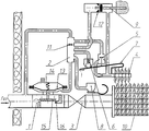
На чертеже дана модулируемая атмосферная газовая горелка, общий вид.The drawing shows a modulated atmospheric gas burner, General view.
Осуществление изобретенияThe implementation of the invention
Модулируемая атмосферная газовая горелка состоит из газового клапана 1, блока контроля и регулирования 2, крана 3, запальной горелки 4 с датчиком сетевого газа 5, датчиком пламени 6 с термобиметаллической пластиной 7, датчика тяги 8, датчика температуры 9, основной горелки 10, при этом блок контроля и регулирования 2 имеет жиклер 11, а датчик температуры 9 дополнительно снабжен жиклером 12, причем датчик температуры 9 соединен с помощью импульсной трубки (на чертеже не обозначена) с блоком контроля и регулирования 2 посредством жиклера 12, выполненного с возможностью обеспечивания во взаимодействии с жиклером 12 и блоком контроля и регулирования 2 модулируемости горения основной горелки 10 при достижении температуры, заданной датчиком температуры 9, при этом газовый клапан 1 содержит мембрану 13, пружину 14, подвижный жесткий центр 15, седло клапана 16, причем все элементы модулируемой атмосферной газовой горелки соединены импульсными трубками (на чертеже не обозначены).The modulated atmospheric gas burner consists of a
Модулируемая атмосферная газовая горелка работает следующим образом.Modulated atmospheric gas burner operates as follows.
Включение модулируемой атмосферной газовой горелки в работу и срабатывание газового клапана 1 происходит следующим образом: приподнимают термобиметаллическую пластину 7, при этом открывается датчик сетевого газа 5, газ по импульсной трубке поступает в запальную горелку 4, который затем поджигают, после нагрева термобиметаллической пластины 7, последнюю отпускают, датчик пламени 6 закрывается, газ через жиклер 11 поступает в блок контроля и регулирования 2 и затем по импульсным трубкам поступает в подмембранное пространство (на чертеже не обозначено) газового клапана 1, к датчикам тяги 8, пламени 6, через жиклер 12 к датчику температуры 9, причем если датчик тяги 8, датчик температуры 9 и датчик пламени 6 окажутся закрытыми, то в подмембранной полости газового клапана 1 создается давление, под воздействием которого газовый клапан 1 откроется. Открывают кран 3, загорается основная горелка 10, при открытии датчика тяги 8, датчика пламени 6 давление в подмембранной полости газового клапана 1 исчезает и газовый клапан 1 закрывается, погасает основная горелка 10, при этом для запуска основной горелки 10 необходимо произвести повторный розжиг. При приближении температуры теплоносителя к уровню, заданному датчиком температуры 9, сопло последнего медленно открывается, газ из блока контроля и регулирования 2 медленно через жиклер 12 стравливается в запальную горелку 4, давление газа, в блоке контроля и регулирования 2 медленно уменьшается, под действием давлением газа воздействующего на подвижный жесткий центр 15, связанный с мембраной 13 и пружиной 14, подвижный жесткий центр 15 приближается к седлу клапана 16, расход газа через основную горелку 10 уменьшается, теплоноситель охлаждается, сопло датчика температуры 9 медленно закрывается, давление газа в подмембранной полости газового клапана 1 возрастает и, преодолевая сопротивление пружины 14, давление газа на подвижный жесткий центр 15, мембрана 13 приподнимает подвижный жесткий центр 15 над седлом клапана 16, увеличивая расход газа через газовый клапан 1, тем самым увеличивая мощность основной горелки 10, процесс повторяется, при этом при внезапном увеличении давления газа в газопроводе до 3-4 кПа, что на практике иногда встречается, через газовый клапан 1 проходит большее количество газа, основная горелка 10 вырабатывает большее количество тепла, температура теплоносителя повышается, сопло датчика температуры 9 открывается, газ из блока контроля и регулирования 2 через жиклер 12 стравливается в запальную горелку 4, давление газа в блоке контроля и регулирования 2 медленно уменьшается, при этом под действием давления газа, воздействующего на подвижный жесткий центр 15, связанный с мембраной 13 и пружиной 14, подвижный жесткий центр 15 приближается к седлу клапана 16 уже на большую величину, обеспечивая постоянный расход газа через основную горелку 10, причем мощность последней сохраняется на том же уровне, что и до увеличения давления газа, таким образом обеспечивается постоянно необходимая мощность модулируемой атмосферной газовой горелки, заданная датчиком температуры 9.The modulated atmospheric gas burner is turned on and the
Предлагаемое изобретение по сравнению с прототипом и другими известными техническими решениями имеет следующие преимущества:The invention in comparison with the prototype and other known technical solutions has the following advantages:
- упрощение конструкции;- simplification of the design;
- экономичность и устойчивость работы при повышении давления газа;- profitability and stability of work with increasing gas pressure;
- улучшение качества сжигания газа;- improving the quality of gas combustion;
- улучшение экологических показателей горелки без усложнения конструкции;- improving the environmental performance of the burner without complicating the design;
- автоматическое регулирование температуры теплоносителя;- automatic temperature control of the coolant;
- повышение надежности и мощности горелки;- improving the reliability and power of the burner;
- точность пропорционирования расхода газа и воздуха при изменении мощности горелки.- the accuracy of the proportioning of gas and air flow when changing the power of the burner.
Claims (1)
Priority Applications (1)
| Application Number | Priority Date | Filing Date | Title |
|---|---|---|---|
| RU2010106756/06A RU2425287C1 (en) | 2010-02-24 | 2010-02-24 | Modulated atmospheric gas burner |
Applications Claiming Priority (1)
| Application Number | Priority Date | Filing Date | Title |
|---|---|---|---|
| RU2010106756/06A RU2425287C1 (en) | 2010-02-24 | 2010-02-24 | Modulated atmospheric gas burner |
Publications (1)
| Publication Number | Publication Date |
|---|---|
| RU2425287C1 true RU2425287C1 (en) | 2011-07-27 |
Family
ID=44753629
Family Applications (1)
| Application Number | Title | Priority Date | Filing Date |
|---|---|---|---|
| RU2010106756/06A RU2425287C1 (en) | 2010-02-24 | 2010-02-24 | Modulated atmospheric gas burner |
Country Status (1)
| Country | Link |
|---|---|
| RU (1) | RU2425287C1 (en) |
Cited By (2)
| Publication number | Priority date | Publication date | Assignee | Title |
|---|---|---|---|---|
| RU2485403C2 (en) * | 2011-08-01 | 2013-06-20 | Алексей Алексеевич Сердюков | Pilot burner |
| RU2596081C1 (en) * | 2015-02-27 | 2016-08-27 | Алексей Алексеевич Сердюков | Diffusion-kinetic burner |
Citations (5)
| Publication number | Priority date | Publication date | Assignee | Title |
|---|---|---|---|---|
| GB1341987A (en) * | 1971-03-04 | 1973-12-25 | Radiation Ltd | Control systems for gaseous fuel fired appliances |
| GB2232239A (en) * | 1989-02-22 | 1990-12-05 | Cannon Ind Ltd | Gas fired heating unit |
| RU2196939C2 (en) * | 2000-09-05 | 2003-01-20 | Сердюков Алексей Алексеевич | Atmospheric gas burner |
| RU2004124922A (en) * | 2004-08-13 | 2006-02-10 | Алексей Алексеевич Сердюков (RU) | ATMOSPHERIC GAS BURNER |
| RU2331023C1 (en) * | 2006-12-25 | 2008-08-10 | Алексей Алексеевич Сердюков | Modulated atmospheric gas burner |
-
2010
- 2010-02-24 RU RU2010106756/06A patent/RU2425287C1/en active IP Right Revival
Patent Citations (5)
| Publication number | Priority date | Publication date | Assignee | Title |
|---|---|---|---|---|
| GB1341987A (en) * | 1971-03-04 | 1973-12-25 | Radiation Ltd | Control systems for gaseous fuel fired appliances |
| GB2232239A (en) * | 1989-02-22 | 1990-12-05 | Cannon Ind Ltd | Gas fired heating unit |
| RU2196939C2 (en) * | 2000-09-05 | 2003-01-20 | Сердюков Алексей Алексеевич | Atmospheric gas burner |
| RU2004124922A (en) * | 2004-08-13 | 2006-02-10 | Алексей Алексеевич Сердюков (RU) | ATMOSPHERIC GAS BURNER |
| RU2331023C1 (en) * | 2006-12-25 | 2008-08-10 | Алексей Алексеевич Сердюков | Modulated atmospheric gas burner |
Cited By (2)
| Publication number | Priority date | Publication date | Assignee | Title |
|---|---|---|---|---|
| RU2485403C2 (en) * | 2011-08-01 | 2013-06-20 | Алексей Алексеевич Сердюков | Pilot burner |
| RU2596081C1 (en) * | 2015-02-27 | 2016-08-27 | Алексей Алексеевич Сердюков | Diffusion-kinetic burner |
Similar Documents
| Publication | Publication Date | Title |
|---|---|---|
| AU2009270342B2 (en) | System and method to reduce standby energy loss in a gas burning appliance | |
| RU2196939C2 (en) | Atmospheric gas burner | |
| RU2012100305A (en) | DOUBLE FUEL SOURCE OF HEAT | |
| RU2425287C1 (en) | Modulated atmospheric gas burner | |
| RU2596081C1 (en) | Diffusion-kinetic burner | |
| RU2309331C1 (en) | Two-step atmospheric gas burner | |
| RU2331022C1 (en) | Gas valve | |
| RU2319899C1 (en) | Igniting burner | |
| RU2300703C1 (en) | Universal gas controller | |
| RU2430305C1 (en) | Modulated atmospheric gas burner with automatic power adjuster | |
| RU2324113C1 (en) | Double-stage air compound gas burner | |
| RU2331023C1 (en) | Modulated atmospheric gas burner | |
| RU2365820C2 (en) | Double-stage gas burner | |
| RU172713U1 (en) | HEATING INSTALLATION | |
| RU2351848C1 (en) | Energy-independent gas valve | |
| RU2631365C1 (en) | Two-stage diffusion-kinetic burner | |
| RU2370704C1 (en) | Temperature sensor | |
| RU2450215C1 (en) | External boiler | |
| RU2331021C1 (en) | Twin atmospheric gas burner | |
| CA1294344C (en) | Gas-fired furnace control apparatus and method for maintaining an optimum fuel air ratio | |
| RU2399840C1 (en) | Energy-independent gas valve | |
| CN110529847A (en) | Combustor and have its domestic appliance | |
| RU129602U1 (en) | GAS-USING DEVICE SAFETY AUTOMATION | |
| RU2210036C2 (en) | Domestic gas burner for hot-water boilers provided with automatic control systems | |
| RU2211412C2 (en) | Gas burner for hot-water boiler with automatic system |
Legal Events
| Date | Code | Title | Description |
|---|---|---|---|
| MM4A | The patent is invalid due to non-payment of fees |
Effective date: 20130225 |
|
| NF4A | Reinstatement of patent |
Effective date: 20140710 |