RU2425343C1 - Device for determination of connected weight, inertia moments and damping of models of vessels by methods of their free oscillations in liquid - Google Patents
Device for determination of connected weight, inertia moments and damping of models of vessels by methods of their free oscillations in liquid Download PDFInfo
- Publication number
- RU2425343C1 RU2425343C1 RU2009145902/28A RU2009145902A RU2425343C1 RU 2425343 C1 RU2425343 C1 RU 2425343C1 RU 2009145902/28 A RU2009145902/28 A RU 2009145902/28A RU 2009145902 A RU2009145902 A RU 2009145902A RU 2425343 C1 RU2425343 C1 RU 2425343C1
- Authority
- RU
- Russia
- Prior art keywords
- model
- bifilar
- oscillations
- damping
- suspension
- Prior art date
Links
- 230000010355 oscillation Effects 0.000 title claims abstract description 37
- 238000013016 damping Methods 0.000 title claims abstract description 24
- 239000007788 liquid Substances 0.000 title claims description 3
- 238000000034 method Methods 0.000 title abstract description 20
- 239000000725 suspension Substances 0.000 claims abstract description 37
- XLYOFNOQVPJJNP-UHFFFAOYSA-N water Substances O XLYOFNOQVPJJNP-UHFFFAOYSA-N 0.000 abstract description 16
- 230000003068 static effect Effects 0.000 abstract description 6
- 230000000694 effects Effects 0.000 abstract description 2
- 238000005259 measurement Methods 0.000 abstract 1
- 239000000126 substance Substances 0.000 abstract 1
- 230000005484 gravity Effects 0.000 description 6
- 238000002474 experimental method Methods 0.000 description 5
- 238000006073 displacement reaction Methods 0.000 description 3
- 238000005096 rolling process Methods 0.000 description 3
- 238000013461 design Methods 0.000 description 2
- 238000012545 processing Methods 0.000 description 2
- 238000005086 pumping Methods 0.000 description 2
- 238000011084 recovery Methods 0.000 description 2
- 238000007667 floating Methods 0.000 description 1
- 239000012530 fluid Substances 0.000 description 1
- 230000007935 neutral effect Effects 0.000 description 1
- 230000003472 neutralizing effect Effects 0.000 description 1
- 230000003534 oscillatory effect Effects 0.000 description 1
- 230000008092 positive effect Effects 0.000 description 1
- 238000001556 precipitation Methods 0.000 description 1
- 230000001105 regulatory effect Effects 0.000 description 1
- 238000012546 transfer Methods 0.000 description 1
Images
Landscapes
- Aerodynamic Tests, Hydrodynamic Tests, Wind Tunnels, And Water Tanks (AREA)
Abstract
Description
Предлагаемое техническое решение принадлежит к лабораторным установкам, предназначенным для определения присоединенных масс, моментов инерции и демпфирования моделей судов различной формы при их свободных затухающих колебаниях в жидкости в поперечном и продольном направлениях.The proposed technical solution belongs to laboratory facilities designed to determine the attached masses, moments of inertia and damping of ship models of various shapes with their free damped oscillations in the fluid in the transverse and longitudinal directions.
Известен метод кренования судов в натурных условиях и их моделей в лабораторных условиях, по которому определяются их коэффициенты поперечной остойчивости 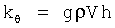
Недостаток этого метода состоит в том, что он позволяет определить присоединенные моменты инерции λ44 и демпфирования µ44 только при бортовых колебаниях моделей (судна) вокруг продольной горизонтальной оси, проходящей через его центр масс, причем только на одной частоте. Однако известно [1], что эти коэффициенты зависят от амплитуды и частоты колебаний (амплитуды и частоты волн).The disadvantage of this method is that it allows you to determine the attached moments of inertia λ 44 and damping µ 44 only for airborne oscillations of the models (vessel) around a longitudinal horizontal axis passing through its center of mass, and at only one frequency. However, it is known [1] that these coefficients depend on the amplitude and frequency of the oscillations (amplitude and frequency of the waves).
Известен способ определения моментов инерции моделей судов (способ бифилярного подвеса), при котором модель подвешивается на двух тросиках одинаковой длины l на воздухе, закрепленных в диаметральной плоскости модели так, чтобы центр тяжести ее был посередине между этими тросиками на расстоянии a [2]. Затем модели сообщается колебательное движение в горизонтальной плоскости вокруг вертикальной оси и замеряется по секундомеру период полного колебания. Момент инерции модели относительно вертикальной оси, проходящей через центр масс G, определяется по формулеThere is a method of determining the moments of inertia of ship models (bifilar suspension method), in which the model is suspended on two cables of the same length l in air, fixed in the diametrical plane of the model so that its center of gravity is in the middle between these cables at a distance [2]. Then the oscillatory motion in the horizontal plane around the vertical axis is reported to the model and the period of complete oscillation is measured by the stopwatch. The moment of inertia of the model relative to the vertical axis passing through the center of mass G is determined by the formula

где P=gM - сила тяжести модели - прототип.where P = gM - model gravity - prototype.
Но это техническое решение не позволяет определять присоединенные моменты инерции и демпфирования в воде, т.к. в этом случае сила тяжести модели P уравновешивается силами ее плавучести FA=gρV. В этом случае при отклонении не возникают восстанавливающие моменты, и поэтому собственная качка моделей невозможна. Однако при определенной модернизации этого способа он может быть применен при колебаниях моделей и в воде.But this technical solution does not allow to determine the attached moments of inertia and damping in water, because in this case, the gravity model P is balanced by the forces of its buoyancy F A = gρV. In this case, when deviating, restoring moments do not arise, and therefore, proper rolling of the models is impossible. However, with a certain modernization of this method, it can be applied to fluctuations of models and in water.
Цель изобретения - расширение функциональных возможностей известного технического решения. Указанная цель достигается тем, что в известном техническом решении, включающем модель судна, устройство ее бифилярного подвеса к опорам, аппаратуру для измерения и записи ее свободных колебаний во времени. Устройство бифилярного подвеса выполнено с возможностью изменения длины подвеса l и расстояния между бифилярами а, модель содержит устройства присоединения бифилярных подвесов к корпусу в продольном и поперечном направлениях с возможностью регулирования высоты закрепления на них бифилярных подвесов на уровне высоты центра масс модели и выше его, а также имеет возможность приема дополнительного балласта (груза) сверх расчетной нагрузки, при этом устройство бифилярного подвеса модели устанавливается над гидролотком, в который опускается модель по расчетную ватерлинию.The purpose of the invention is the expansion of the functionality of the known technical solutions. This goal is achieved by the fact that in the known technical solution, including the model of the vessel, the device of its bifilar suspension to the supports, equipment for measuring and recording its free oscillations in time. The bifilar suspension device is made with the possibility of changing the suspension length l and the distance between the bifilars a, the model contains devices for connecting the bifilar suspensions to the body in the longitudinal and transverse directions with the possibility of adjusting the height of the bifilar suspensions on them at the level of the center of mass of the model and above it, and has the ability to receive additional ballast (load) in excess of the calculated load, while the device bifilar suspension of the model is installed above the hydrohole, in which the lower Smiling model on the design waterline.
Ниже на фиг.1 показано предлагаемое устройство для определения присоединенных масс λ11 и λ33, присоединенных моментов инерции модели λ44, λ55 и демпфирования µ22, µ33, µ44, µ55 методом колебаний в воде. Оно включает:Figure 1 shows the proposed device for determining the attached masses λ 11 and λ 33 , the attached moments of inertia of the model λ 44 , λ 55 and damping µ 22 , µ 33, µ 44 , µ 55 by the method of oscillations in water. It includes:
- модель 1, в которой находятся:- Model 1, in which are located:
- устройства присоединения бифилярных подвесов к корпусу модели в продольном и поперечном направлениях 2, включающие талрепы для регулирования высоты закрепления на них бифилярных подвесов на уровне высоты центра масс модели и выше,- devices for connecting bifilar suspensions to the model body in the longitudinal and
- тарировочные устройства 3 для перемещения тарировочных грузов в поперечной и продольной плоскостях для создания углов крена и дифферента,- calibration devices 3 for moving calibration weights in the transverse and longitudinal planes to create roll and trim angles,
- место приема дополнительного (балластного) груза 4,- place of reception of additional (ballast) cargo 4,
- дополнительный (балластный) груз 5,- additional (ballast) load 5,
- аппаратура для измерения колебаний модели 6,- equipment for measuring oscillations of
- бифилярные подвесы (тросики) 7,- bifilar suspensions (cables) 7,
- устройство закрепления бифиляров на горизонтальной оси 8, которая может подниматься на разную высоту двумя вертикальными раздвижными телескопическими штангами 9,- a device for securing bifilars on a horizontal axis 8, which can be raised to different heights by two vertical telescopic sliding rods 9,
- устройство для регулирования длины бифилярных подвесов 10, например, в виде катушек с храповым механизмом, находящихся на оси 8,- a device for regulating the length of the bifilar suspensions 10, for example, in the form of coils with a ratchet mechanism located on the axis 8,
- гидролоток 11.- hydroflow 11.
Предложенное устройство работает следующим образом.The proposed device operates as follows.
1. Вначале модель в сборе отдельно от устройства взвешивается, вывешивается на призме и определяется ее масса mм и положение ее центра масс по длине XG при нейтральном положении тарировочных грузов.1. First, the complete model, separately from the device, is weighed, hung on the prism and its mass m m and the position of its center of mass along the length X G are determined with the neutral position of the calibration weights.
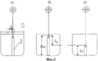
2. Модель на воздухе подвешивается на бифилярах, которые закрепляются на устройстве ее подвески, поднятом в верхнее положение (фиг.2, а), и производится ее статическая тарировка. С этой целью тарировочный груз, находящийся в исходном положении посередине модели, перемещается на расстояния b1, b2, b3, от середины и фиксируются углы крена θ1, θ2, θ3.2. The model is suspended in air on bifilars, which are fixed on the device of its suspension, raised to the upper position (Fig.2, a), and its static calibration is performed. For this purpose, the calibration weight, which is in the initial position in the middle of the model, moves at distances b 1 , b 2 , b 3 from the middle and the roll angles θ 1 , θ 2 , θ 3 are fixed.
Из сравнения кренящего моментаFrom a comparison of heeling moment

с восстанавливающим 
находится для разных bi удаление центра масс всей системы lGi от горизонтального уровня подвеса модели yG (фиг.2, б).is for different b i the removal of the center of mass of the entire system l Gi from the horizontal level of the suspension model y G (Fig.2, b).
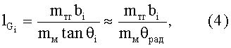

Измерив удаление основания модели от оси подвеса yпв, можно найти удаление центра масс модели yG от ее основания yG=yпв-lG, как показано на фиг.2, в.By measuring the distance of the base of the model from the suspension axis y pv , one can find the distance of the center of mass of the model y G from its base y G = y pv -l G , as shown in Fig. 2, c.
3. Тарировочный груз возвращается в исходное положение, чтобы крена или дифферента не было. После этого модель отклоняется на угол θ и определяется период колебаний τ, и по известной формуле [1] определяется момент инерции модели относительно горизонтального уровня подвеса3. The calibration weight is returned to its original position so that there is no roll or trim. After that, the model deviates by an angle θ and the period of oscillations τ is determined, and according to the well-known formula [1], the moment of inertia of the model relative to the horizontal suspension level is determined
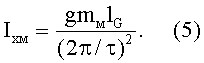
Собственный момент инерции модели определяется по формулеThe proper moment of inertia of the model is determined by the formula

Методика определения присоединенных масс, моментов инерции и демпфирования моделей судов методами их свободных колебаний в воде заключается в следующем.The methodology for determining the attached masses, moments of inertia and damping of ship models by the methods of their free vibrations in water is as follows.
1. Устройства регулирования высоты закрепления бифиляров на модели устанавливаются на уровне уже определенного центра масс модели, и бифиляры закрепляются на этом уровне. Устанавливается некоторая средняя высота оси 8 закрепления бифиляров.1. Devices for adjusting the height of fastening of bifilars on the model are installed at the level of a certain center of mass of the model, and the bifilars are fixed at this level. A certain average height of the axis 8 of fixing the bifilars is established.
2. Модель опускается в гидролоток, в котором она должна находиться в положении равновесия. Если модель не точно соответствует расчетной посадке, то с помощью небольших дополнительных тарировочных грузов mдтг обеспечивается ее статическое равновесие без крена и дифферента по расчетной осадке. Производится кренование модели в исходном состоянии с помощью перемещения тарировочных грузов.2. The model is lowered into the hydrohole, in which it must be in the equilibrium position. If the model does not exactly correspond to the calculated fit, then with the help of small additional calibration weights m dtg its static equilibrium is provided without a roll and trim on the calculated draft. The model is heeled in the initial state by moving calibration cargoes.
Кренящий момент от них будет 

Из равенства 
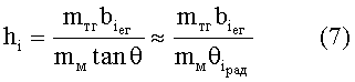
и на основе нескольких опытов находится ее среднее значение h°. Определяется коэффициент поперечной остойчивости модели 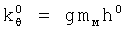
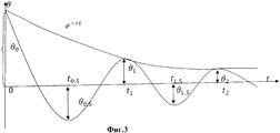
3. Тарировочные грузы возвращаются в исходное положение, при котором крен θ=0. Модель отклоняется на углы |θ|<8÷10° и отпускается. Аппаратурой (6) записываются ее затухающие колебания на тихой воде типа фиг.3. Эти колебания идентифицируются уравнением:3. Calibration weights are returned to their original position at which the roll θ = 0. The model deviates by angles | θ | <8 ÷ 10 ° and is released. The apparatus (6) records its damped oscillations in still water of the type of FIG. 3. These vibrations are identified by the equation:

где: (Ixm+λ44) - суммарный момент инерции модели с присоединенным моментом жидкости λ44;where: (I xm + λ 44 ) is the total moment of inertia of the model with the attached liquid moment λ 44 ;
Nθ - коэффициент демпфирования угловых колебаний модели в воде.N θ is the damping coefficient of the angular oscillations of the model in water.
Уравнение (8) приводится к стандартному виду:Equation (8) is reduced to the standard form:


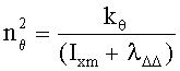
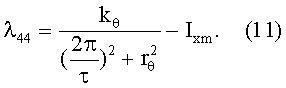
Определив из опытов средний период τ частоту затухающих колебаний σ=2π/τ, а также известными методами [1]и [3] найдя логарифмический декремент затухания rθ, можно вычислятьHaving determined the average period τ from the experiments, the frequency of the damped oscillations σ = 2π / τ, as well as by finding the logarithmic damping decrement r θ by the known methods [1] and [3], we can calculate

и найти присоединенный момент инерции модели λ44 при ее колебаниях вокруг продольной оси, проходящий через центр ее массand find the attached moment of inertia of the model λ 44 when it oscillates around the longitudinal axis, passing through the center of mass
Полученные таким традиционным путем значения λ44 и rθ соответствуют минимальной (собственной) частоте модели.The values λ 44 and r θ obtained in such a traditional way correspond to the minimum (natural) frequency of the model.
4. Принимается первая порция основного балластного груза mБГ, и натяжением бифилярных подвесов модель выставляется на исходную ватерлинию. После этого производится кренование модели в воде с этим грузом по методики п.2. С этой целью основной тарировочный груз, находящийся в исходном положении посередине модели, перемещается в поперечном направления на расстояния b1, b2, b3 и определяются соответствующие углы крена и вычисляются соответствующие кренящие моменты4. The first portion of the main ballast load m BG is accepted, and the model is set to the initial waterline by tensioning the bifilar suspensions. After that, the model is heeled in water with this cargo according to the methodology of

восстанавливающий момент представляется из теории корабля выражениемrecovery moment is represented from the theory of the ship by the expression

в котором метацентрическая высота hi, нормируется на ρV=const=mм.in which the metacentric height h i is normalized to ρV = const = m m .
Из равенства
Вычисляется его математическое ожидание (среднее значение) 

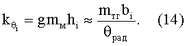
5. Модель отклоняется на некоторый угол θ<8÷10° и отпускается. Аппаратурой (6) записываются затухающие бортовые колебания модели на тихой воде, аналогичные фиг.3, но с большей частотой. Они идентифицируются уравнением:5. The model deviates by a certain angle θ <8 ÷ 10 ° and is released. The apparatus (6) records the damped airborne oscillations of the model in quiet water, similar to Fig. 3, but with a higher frequency. They are identified by the equation:

где: 
Nθ - коэффициент демпфирования угловых колебаний модели в воде.N θ is the damping coefficient of the angular oscillations of the model in water.
Уравнение (14) приводится к стандартному виду:Equation (14) is reduced to the standard form:

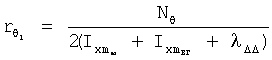
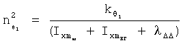
Определив из серии опытов средний период колебаний τ1 и путем обработки кривой фиг.3 коэффициент демпфирования 


где 

Значение 

Конструкция предлагаемого устройства позволяет изменять длину бифилярных подвесов и массу балластных грузов и определять присоединенные моменты инерции и демпфирования при разных водоизмещениях и частотах. Для увеличения частоты колебания модели увеличивается дополнительный груз, и с помощью натяжения бифилярного подвеса обеспечивается ее равновесие при той же осадке. Может изменяться длина подвесов. Для каждого сочетания длины подвеса и балластного груза производится статическая тарировка модели и определяется другой коэффициент остойчивости. Для каждого сочетания mБГ и lподвеса проводится серия опытов по п.4.The design of the proposed device allows you to change the length of the bifilar suspensions and the mass of ballast weights and determine the attached moments of inertia and damping at different displacements and frequencies. To increase the oscillation frequency of the model, an additional load is increased, and by means of the tension of the bifilar suspension, its equilibrium is ensured with the same draft. Suspension lengths may vary. For each combination of suspension length and ballast weight, the model is statically calibrated and a different stability coefficient is determined. For each combination of m BG and l suspension , a series of experiments is carried out according to claim 4.
Проведя качку с разными балластными грузами и длиной подвеса с помощью предложенного устройства, можно найти тенденцию изменения λ44 и µ44 от частоты.After rolling with different ballast weights and the length of the suspension using the proposed device, you can find a tendency for λ 44 and μ 44 to change in frequency.
Аналогичным образом могут быть определены присоединенные моменты инерции и демпфировании λ66 и µ66 при продольных колебаниях.In a similar way, the attached moments of inertia and damping of λ 66 and µ 66 during longitudinal vibrations can be determined.
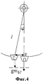
Предложенное устройство позволяет на бифилярных подвесах приближенно определять также присоединенные массы λ33, λ11 и демпфирования µ33, µ11 колебаниях моделей в горизонтальной плоскости вдоль поперечной оси Z и продольной оси X, что не позволял делать прототип. Методику их определения иллюстрирует фиг.4. При небольших горизонтальных перемещениях модели и достаточной длине подвеса, при углах |φ|<6-7°, дуга, по которой будет двигаться модель под действием сил избыточной тяжести (сила тяжести самой модели уравновешивается силой ее плавучести), будет практически плоской. Небольшое подвсплытие модели при ее перемещении по горизонтали может быть учтено при статической тарировке. Присоединив к модели устройство измерения отклоняющих сил (например, применив тарировочные грузы mтг через блок) и замерив соответствующие линейные отклонения модели zi от вертикального положения, можно найти выражение для восстанавливающих сил FB=gmБГεz=gmтг, где ε - коэффициент, учитывающий подвсплытие модели при ее отклонении Z от статического равновесия в нулевом положении. Величина отклонений 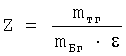

Колебание модели в горизонтальной плоскости вдоль оси Z в этом случае описывается уравнениемThe oscillation of the model in the horizontal plane along the Z axis in this case is described by the equation

Оно также приводится к стандартному видуIt is also brought to standard view.

где 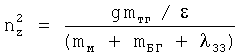
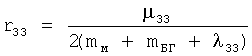
По результатам записи горизонтальных колебаний, характер которых будет идентичен фиг.3 и по аналогии с вышеизложенной методикой, могут быть найдены r33 и τz.According to the results of recording horizontal oscillations, the nature of which will be identical to Fig. 3 and by analogy with the above methodology, r 33 and τ z can be found.


а затем 

Аналогично можно определить λ11 и µ11 при горизонтальной качке модели вдоль продольной оси X.Similarly, we can determine λ 11 and μ 11 for horizontal rolling of the model along the longitudinal axis X.
Необходимо отметить, что в теории колебаний математического и физического маятника [4] доказывается, что период их колебаний под действием гравитационных сил не зависит от массы маятника, а определяется только отношением 
Предложенное устройство существенно расширяет экспериментальные возможности известного технического решения бифилярного подвеса:The proposed device significantly expands the experimental capabilities of the well-known technical solutions bifilar suspension:
- оно позволяет применить его в условиях нейтрализации силы тяжести модели силами ее плавучести в воде за счет применения избыточного балластного груза и обеспечения модели неизменной осадки за счет натяжения бифилярных подвесов;- it allows you to apply it in the conditions of neutralizing the gravity of the model by the forces of its buoyancy in water due to the use of excess ballast weight and providing a model of constant draft due to the tension of bifilar suspensions;
- очень просто и легко (за счет применения разных балластных грузов и длины подвесов и их натяжения) решаются вопросы определения присоединенных масс, моментов инерции и демпфирования модели судов в воде при разных осадках и водоизмещениях при разных частотах;- it is very simple and easy (due to the use of different ballast weights and the length of the suspensions and their tension), the issues of determining the attached masses, moments of inertia and damping of the ship model in water at different precipitation and displacement at different frequencies are solved;
- решает проблему нахождения присоединенных масс и моментов инерции модели судов в воде без применения механических систем и сложных и дорогих конструкций, которые содержат устройства вынужденной качки;- solves the problem of finding the attached masses and moments of inertia of the model of ships in water without the use of mechanical systems and complex and expensive structures that contain forced pumping devices;
- оно позволяет определять присоединенные массы и демпфирование модели при ее горизонтальных колебаниях на подвесах вдоль поперечной и продольной осей, что не позволяет известное техническое решение;- it allows you to determine the attached mass and damping of the model with its horizontal vibrations on suspensions along the transverse and longitudinal axes, which does not allow the known technical solution;
- за счет применения известной методики обработки результатов эксперимента [3] оно обеспечивает близкую к методам вынужденных колебаний точность, отличаясь простотой и дешевизной. Поэтому предлагаемое техническое решение отвечает критерию существенного положительного эффекта.- due to the application of the well-known methods of processing the results of the experiment [3], it provides accuracy close to the methods of forced vibrations, being simple and cheap. Therefore, the proposed technical solution meets the criterion of a significant positive effect.
Патентный поиск не выявил подобного технического решения, поэтому предложение обладает патентной новизной.Patent search did not reveal such a technical solution, therefore, the proposal has patent novelty.
Устройство отвечает критерию реализуемости, так как оно выполняется из общедоступных элементов.The device meets the criterion of feasibility, since it is made from publicly available elements.
Источники информацииInformation sources
1. Справочник по теории корабля под ред. Я.И.Войтунского, т.2 (Статика судов. Качка судов). Л.: Изд-во «Судостроение», 1985 г.1. Handbook of ship theory, ed. Ya.I. Voytunskogo, t.2 (Statics of ships. Pumping of ships). L .: Publishing house "Shipbuilding", 1985
2. Благовещенский С.Н. Качка корабля. Л.: Изд-во «Судпромгиз», 1954 г.2. Blagoveshchensky S.N. Ship pitching. L .: Publishing house "Sudpromgiz", 1954
3. Разумеенко Ю.В. Вопросы переноса гидродинамических коэффициентов, определенных методами затухающих колебаний, на колебания вынужденные и воздействие волн на подводные технические объекты. М.: Известия РАН серия МТТ, №1, 1993.3. Razumeenko Yu.V. The issues of transfer of hydrodynamic coefficients, determined by the methods of damped oscillations, to forced oscillations and the effect of waves on underwater technical objects. M .: Izvestia RAN MTT Series, No. 1, 1993.
4. Яблонский А.А., Никифорова В.М. Курс теоретической механики. СПб.: Изд-во «Лань», 2004.4. Yablonsky A.A., Nikiforova V.M. The course of theoretical mechanics. St. Petersburg: Publishing House "Doe", 2004.
Claims (1)
Priority Applications (1)
| Application Number | Priority Date | Filing Date | Title |
|---|---|---|---|
| RU2009145902/28A RU2425343C1 (en) | 2009-12-10 | 2009-12-10 | Device for determination of connected weight, inertia moments and damping of models of vessels by methods of their free oscillations in liquid |
Applications Claiming Priority (1)
| Application Number | Priority Date | Filing Date | Title |
|---|---|---|---|
| RU2009145902/28A RU2425343C1 (en) | 2009-12-10 | 2009-12-10 | Device for determination of connected weight, inertia moments and damping of models of vessels by methods of their free oscillations in liquid |
Publications (1)
| Publication Number | Publication Date |
|---|---|
| RU2425343C1 true RU2425343C1 (en) | 2011-07-27 |
Family
ID=44753654
Family Applications (1)
| Application Number | Title | Priority Date | Filing Date |
|---|---|---|---|
| RU2009145902/28A RU2425343C1 (en) | 2009-12-10 | 2009-12-10 | Device for determination of connected weight, inertia moments and damping of models of vessels by methods of their free oscillations in liquid |
Country Status (1)
| Country | Link |
|---|---|
| RU (1) | RU2425343C1 (en) |
Cited By (3)
| Publication number | Priority date | Publication date | Assignee | Title |
|---|---|---|---|---|
| CN106017797A (en) * | 2016-05-12 | 2016-10-12 | 中国航空工业集团公司西安飞机设计研究所 | Unmanned aerial vehicle inertia measuring device and unmanned aerial vehicle inertia measuring method |
| RU2667434C1 (en) * | 2017-11-20 | 2018-09-19 | Федеральное государственное бюджетное образовательное учреждение высшего образования "Калининградский государственный технический университет" | Method of testing ship hull models |
| RU2688964C1 (en) * | 2018-06-27 | 2019-05-23 | федеральное государственное автономное образовательное учреждение высшего образования "Санкт-Петербургский национальный исследовательский университет информационных технологий, механики и оптики" (Университет ИТМО) | Method for identification of tensor of connected moment of inertia of body and device for its implementation |
-
2009
- 2009-12-10 RU RU2009145902/28A patent/RU2425343C1/en active
Non-Patent Citations (1)
| Title |
|---|
| БЛАГОВЕЩЕНСКИЙ С.Н. Качка корабля. - Л.: Изд-во «Судпромгиз», 1954. Справочник по теории корабля «Статика судов. Качка корабля» т.2 под редакцией Я.И.Войткунского. - Л.: Судостроение, 1985, с.417-419. РАЗУМЕЕНКО Ю.В. Вопросы переноса гидродинамических коэффициентов, определенных методами затухающих колебаний, на колебания вынужденные или воздействие волн на подводные технические объекты. - М.: Изд. АН. «Механика твердого тела», №1, 1993. ЯБЛОНСКИЙ А.А., НИКИФОРОВА В.М. Курс теоретической механики. - СПб.: Изд-во «Лань», 2004. * |
Cited By (4)
| Publication number | Priority date | Publication date | Assignee | Title |
|---|---|---|---|---|
| CN106017797A (en) * | 2016-05-12 | 2016-10-12 | 中国航空工业集团公司西安飞机设计研究所 | Unmanned aerial vehicle inertia measuring device and unmanned aerial vehicle inertia measuring method |
| CN106017797B (en) * | 2016-05-12 | 2019-02-12 | 中国航空工业集团公司西安飞机设计研究所 | Inertia measurement device for unmanned aerial vehicle and inertial measurement method for unmanned aerial vehicle |
| RU2667434C1 (en) * | 2017-11-20 | 2018-09-19 | Федеральное государственное бюджетное образовательное учреждение высшего образования "Калининградский государственный технический университет" | Method of testing ship hull models |
| RU2688964C1 (en) * | 2018-06-27 | 2019-05-23 | федеральное государственное автономное образовательное учреждение высшего образования "Санкт-Петербургский национальный исследовательский университет информационных технологий, механики и оптики" (Университет ИТМО) | Method for identification of tensor of connected moment of inertia of body and device for its implementation |
Similar Documents
| Publication | Publication Date | Title |
|---|---|---|
| Irkal et al. | CFD approach to roll damping of ship with bilge keel with experimental validation | |
| Harnois et al. | Numerical model validation for mooring systems: Method and application for wave energy converters | |
| RU2425343C1 (en) | Device for determination of connected weight, inertia moments and damping of models of vessels by methods of their free oscillations in liquid | |
| KR20150062238A (en) | apparatus for measuring added resistance in waves | |
| Yang et al. | Experimental study on the wave-induced dynamic response and hydrodynamic characteristics of a submerged floating tunnel with elastically truncated boundary condition | |
| Chakrabarti et al. | Wave forces on vertical circular cylinder | |
| RU2378616C1 (en) | Celestial guidance system | |
| Hinrichsen | Bifilar suspension measurement of boat inertia parameters | |
| Le Cunff et al. | Experimental and numerical study of heave-induced lateral motion (HILM) | |
| Kjelldorff et al. | Water current measurements using oceanographic bottom lander LoTUS | |
| US11371841B2 (en) | System and method of tilt sensor tide and inland water level gauge | |
| RU2561229C1 (en) | Buoy for determination of characteristics of sea wind waves | |
| WO2016076458A1 (en) | Device for measuring pitching moment of inertia and height of center of gravity of model ship | |
| CN202029988U (en) | Float model mass distribution adjusting device | |
| RU2425344C1 (en) | Device for determination of forces of added inertia and damping bodies by method of their free damping vibrations in liquid | |
| Taravella et al. | A segmented model test of a container ship in head seas | |
| Krata | Linear characteristics of the sloshing phenomenon for the purpose of on-board ship's stability assessment | |
| CN115079576B (en) | Amplitude-frequency characteristic parameter acquisition method based on UAV recovery and landing under ship shaking | |
| Djebli et al. | The application of a smartphone in ship stability experiment | |
| Gryazin et al. | Inertial measurement unit of waverider buoy. Development and test results | |
| RU2562445C2 (en) | Test bench for measurement of stato-dynamic characteristics of physical objects | |
| Park et al. | New Methodology in Analysis of Physical Properties and Roll Decay with Uncertainty Estimates for Surface-Ship Model Experiments | |
| RU2652173C2 (en) | Complex for measuring the characteristics of spatial oscillations of floating objects in the experimental (wave) basin | |
| Candela et al. | Bessel’s improved Kater pendulum in the teaching lab | |
| Ivanova et al. | Experimental researches automation of spatial oscillations of the floating ocean engineering systems in the wave basin |