RU2425392C1 - Method and device for optoelectronic all-round view - Google Patents
Method and device for optoelectronic all-round view Download PDFInfo
- Publication number
- RU2425392C1 RU2425392C1 RU2010114957/09A RU2010114957A RU2425392C1 RU 2425392 C1 RU2425392 C1 RU 2425392C1 RU 2010114957/09 A RU2010114957/09 A RU 2010114957/09A RU 2010114957 A RU2010114957 A RU 2010114957A RU 2425392 C1 RU2425392 C1 RU 2425392C1
- Authority
- RU
- Russia
- Prior art keywords
- radiation
- phase
- azimuthal plane
- rotation
- code
- Prior art date
Links
- 238000000034 method Methods 0.000 title claims abstract description 17
- 230000005693 optoelectronics Effects 0.000 title claims abstract description 13
- 230000005855 radiation Effects 0.000 claims abstract description 43
- 230000003287 optical effect Effects 0.000 claims abstract description 14
- 239000011159 matrix material Substances 0.000 claims abstract description 6
- 238000012552 review Methods 0.000 claims description 5
- 238000013461 design Methods 0.000 claims description 3
- 230000000694 effects Effects 0.000 abstract 1
- 238000005259 measurement Methods 0.000 abstract 1
- 239000000126 substance Substances 0.000 abstract 1
- 238000010586 diagram Methods 0.000 description 3
- 238000005516 engineering process Methods 0.000 description 2
- 238000013459 approach Methods 0.000 description 1
- 230000015572 biosynthetic process Effects 0.000 description 1
- 244000309464 bull Species 0.000 description 1
- 230000003247 decreasing effect Effects 0.000 description 1
- 238000001514 detection method Methods 0.000 description 1
- 238000012545 processing Methods 0.000 description 1
- 230000001105 regulatory effect Effects 0.000 description 1
- 230000009466 transformation Effects 0.000 description 1
Images
Landscapes
- Closed-Circuit Television Systems (AREA)
Abstract
Description
Предлагаемые изобретения относятся к области приборостроения, измерительной и информационной техники, точнее к оптико-электронному обнаружению движущихся объектов.The proposed invention relates to the field of instrumentation, measuring and information technology, more specifically to the optoelectronic detection of moving objects.
Известен способ видеонаблюдения с использованием домашнего видеомагнитофона [см. заявку на патент (РФ) №2006114896, кл. H04N 5/765 от 20.11.2007 г., Бюл. 32], включающий видеокамеру наблюдения (видеоглазок), устройство, определяющее период записи сигнала на магнитофон (детектор движения) и устройство сопряжения видеомагнитофона и детектора движения, вместо контроллера механического нажатия кнопок «Start» или «Stop» пульта дистанционного управления предлагается использовать триггерное устройство сопряжения видеомагнитофона и детектора движения, замыкающее на время около 1с клеммы записи или отмены записи видеомагнитофона «Rec» или «Stop» соответственно и тем самым включающее запись на период записи или отключающее ее.A known method of video surveillance using a home video recorder [see patent application (RF) No. 2006114896, cl. H04N 5/765 of November 20, 2007, Bull. 32], including a surveillance video camera (video peephole), a device that determines the period of recording a signal on a tape recorder (motion detector) and a pairing device for a video recorder and motion detector, instead of a controller for mechanically pressing the “Start” or “Stop” buttons on the remote control, it is proposed to use a trigger pairing device VCR and motion detector, closing for about 1s the recording terminal or recording cancellation of the VCR “Rec” or “Stop”, respectively, and thereby including recording for the period records or disconnecting it.
Недостатками данного способа являются относительная сложность и недостаточная информативность видеонаблюдения.The disadvantages of this method are the relative complexity and lack of information content of video surveillance.
Известно устройство видеонаблюдения, содержащее первичный импульсный преобразователь, цифро-аналоговый преобразователь, усилитель мощности, электрический привод (см., например, Высокоскоростные купольные камеры. - ИТ портал techlabs. by, 2009 г.).A video surveillance device is known that contains a primary pulse converter, a digital-to-analog converter, a power amplifier, an electric drive (see, for example, High-speed dome cameras. - IT portal techlabs. By, 2009).
Недостатками данного устройства являются сложность и недостаточная информативность видеонаблюдения при круговом обзоре.The disadvantages of this device are the complexity and lack of information content of video surveillance with a circular review.
За прототип приняты способ и устройство оптико-электронного кругового обзора (см. патент №2321016 (РФ), кл. G01S 3/78, 2008 г., БИ №9, ч.4), организующие прием ИК-излучения, прием лазерного излучения и формирование информационного сигнала. Прием ИК-излучения выполнен с возможностью вращения в азимутальной плоскости приводом с датчиком угла и состоит из трех идентичных измерительных ИК-каналов, каждый из которых имеет объектив, плоское зеркало, фотоприемное устройство и блок обработки сигнала. Оси указанных объективов равномерно развернуты в азимутальной плоскости и наклонены к ней по вертикали под различными углами. Прием лазерного излучения выполнен панорамным, фотоприем организован в виде секторно-кольцевой многоплощадочной структуры и формирователь сигнала наличия лазерного излучения и его направления в азимутальной плоскости.For the prototype adopted the method and device of the optoelectronic circular review (see patent No. 2221016 (RF), CL G01S 3/78, 2008, BI No. 9, part 4), organizing the reception of infrared radiation, reception of laser radiation and the formation of an information signal. Reception of IR radiation is made with the possibility of rotation in the azimuthal plane by a drive with an angle sensor and consists of three identical measuring IR channels, each of which has a lens, a flat mirror, a photodetector and a signal processing unit. The axes of these lenses are uniformly deployed in the azimuthal plane and inclined vertically to it at different angles. Laser reception was made panoramic; photo reception was organized in the form of a sector-ring multi-site structure and a signal shaper for the presence of laser radiation and its direction in the azimuthal plane.
Недостатками прототипов являются избыточная сложность и недостаточная информативность видеонаблюдения.The disadvantages of the prototypes are excessive complexity and lack of information content of video surveillance.
Технической задачей способа и устройства оптико-электронного кругового обзора является упрощение и повышение информативности видеонаблюдения.The technical task of the method and device of the optoelectronic circular review is to simplify and increase the information content of video surveillance.
Поставленная техническая задача достигается тем, что:The technical task is achieved in that:
1. В способе оптико-электронного кругового обзора, включающем прием ИК- и оптического излучения с возможностью вращения в азимутальной плоскости по многофазному углу поворота, формирование сигнала наличия излучения и его направления в азимутальной плоскости, в отличие от прототипа, оптическое излучение изображения регистрируют видеосъемкой синхронно с приемом ИК-излучения, размещаемого на объекте видеосъемки за счет сканирования в азимутальной плоскости соответствующего угла поворота фазы тактовыми импульсами фиксированной частоты.1. In the method of optoelectronic circular viewing, including receiving infrared and optical radiation with the possibility of rotation in the azimuthal plane along the multiphase angle of rotation, generating a signal for the presence of radiation and its direction in the azimuthal plane, in contrast to the prototype, the optical radiation of the image is recorded by video synchronously with the reception of infrared radiation placed on a video object due to scanning in the azimuthal plane of the corresponding phase rotation angle by fixed-frequency clock pulses .
2. В способе по п.1, в отличие от прототипа, сканирование угла поворота фазы преобразуют в код пропорционально тактовым импульсам от начала регистрации реверсивного приращения фазы до его обнуления за счет измерения кода Nj, последовательным приближением с нормированным значением N0j по условию: если измеряемый код Nj больше нормируемого N0j, последний увеличивают суммированием импульсов, в противном случае - их вычитанием, при тождественности кодов Nj=N0j число импульсов не изменяют, а нормируемый код принимают за измеренный.2. In the method according to claim 1, in contrast to the prototype, the phase rotation angle scan is converted into a code in proportion to the clock pulses from the beginning of the registration of the reverse phase increment to its zeroing by measuring the code N j , by successive approximation with the normalized value N 0j by the condition: if the measured code N j is larger than the normalized N 0j , the latter is increased by summing the pulses, otherwise, by subtracting them, if the codes N j = N 0j are identical, the number of pulses is not changed, and the normalized code is taken as the measured one.
3. В устройстве оптико-электронного кругового обзора, содержащем блоки приема ИК- и оптического излучения с возможностью вращения в азимуталь ной плоскости приводом с датчиком угла поворота фазы в виде секторно-кольцевой многофазной структуры и формирователем сигнала наличия излучения и его направления в азимутальной плоскости, в отличие от прототипа, приемником оптического излучения служит видеокамера, водруженная на сканер блока приема ИК-излучения, организующего вращение в азимутальной плоскости приводом с ИК-датчиком угла поворота фазы, расположенным соосно между подвижной и неподвижной секторно-кольцевыми структурами сканера.3. In the device of the optoelectronic circular view, containing blocks for receiving infrared and optical radiation with the possibility of rotation in the azimuthal plane by a drive with a phase angle sensor in the form of a sector-ring multiphase structure and a signal conditioner of the presence of radiation and its direction in the azimuthal plane, unlike the prototype, an optical radiation receiver is a video camera mounted on a scanner of an IR radiation receiving unit, which organizes rotation in the azimuthal plane by a drive with an IR rotation angle sensor and the phase, located coaxially between the movable and stationary sector-ring structures of the scanner.
4. В устройстве по п.3., в отличие от прототипа, приемником ИК- излучения служит фотодиодная матрица, включенная по схеме многофазного мостового коммутатора, состоящего из параллельного соединения двух делителей напряжения, организованных из последовательного включения резистора и фазных фотодиодов матрицы, причем входная диагональ многофазного мостового коммутатора служит для подключения источника энергии, а его выходная диагональ нагружена на исполнительный механизм привода сканера устройства.4. In the device according to claim 3., In contrast to the prototype, the infrared radiation receiver is a photodiode array included in a multiphase bridge switch circuit consisting of a parallel connection of two voltage dividers, organized from the series connection of a resistor and matrix phase photodiodes, the input the diagonal of the multiphase bridge switch is used to connect the energy source, and its output diagonal is loaded on the actuator drive of the scanner device.
5. В устройстве по п.3, в отличие от прототипа, формирователь сигнала наличия излучения и его направления в азимутальной плоскости выполнен на ИК-светодиоде с автономным источником питания в форме декоративного исполнения, например значка, размещаемого на объекте съемки.5. In the device according to
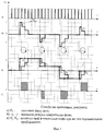
Сущность способа и устройства поясняется фиг.1-4 на уровне временных диаграмм фиг.1 и погрешности фиг.2, кинематических фиг.3 и структурной фиг.4 схем.The essence of the method and device is illustrated in figure 1-4 at the level of time diagrams of figure 1 and the error of figure 2, kinematic figure 3 and structural figure 4 schemes.
Предлагаемый способ (фиг.1) оптико-электронного кругового обзора включает прием ИК и оптического излучения с возможностью вращения видеокамеры в азимутальной плоскости по многофазному углу φ поворота видеоизображения. Оптическое излучение изображения регистрируют видеосъемкой. Вращение на угол φ осуществляется синхронно с приемом ИК-излучения детектором движения на i сегментов, ![]()
![]()
Частота F0 определяется минимальным кодом N0=1 за период Т0:The frequency F 0 is determined by the minimum code N 0 = 1 for the period T 0 :
F0≥N0/T0=1/0,1=10 ГцF 0 ≥N 0 / T 0 = 1 / 0.1 = 10 Hz
Сканирование угла поворота фазы φi преобразуют в код N пропорционально тактовым импульсам частотой F0 за интервал времени τj (см. фиг.1). Это соответствует времени от начала регистрации реверсивного приращения фазы Δφj до его обнуления последовательным приближением нормированного значения N0j к измеряемому значению Nj по условиюScanning the angle of rotation of the phase φ i is converted into code N in proportion to the clock pulses of frequency F 0 for the time interval τ j (see figure 1). This corresponds to the time from the beginning of the registration of the reverse phase increment Δφ j to its zeroing by the successive approximation of the normalized value N 0j to the measured value N j according to the condition
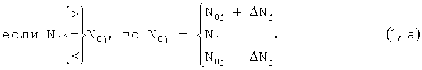
Если измеряемый код Nj больше нормируемого N0j, то его увеличивают суммированием импульсов N0j=N0j+ΔNj. Когда Nj меньше нормы N0j, последний уменьшают вычитанием импульсов N0j=N0j-ΔNj. При тождественности кодов Nj=N0j число импульсов не изменяют, а нормированный код принимают за измеренный. Алгоритм последовательного приближения соответствует алгебраическому суммированию реверсивных приращений ΔNj=Nj-N0.If the measured code N j is larger than the normalized N 0j , then it is increased by summing the pulses N 0j = N 0j + ΔN j . When less than normal N j N 0j, the latter is reduced by subtracting pulses N 0j = N 0j -ΔN j. With the identity of the codes N j = N 0j, the number of pulses is not changed, and the normalized code is taken as the measured one. The sequential approximation algorithm corresponds to the algebraic summation of the reverse increments ΔN j = N j -N 0 .
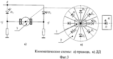
Предлагаемый способ реализует устройство оптико-электронного кругового обзора (см. фиг.3) с использованием видеокамеры (1), включающей видеомагнитофон, ИК-детектор движения (2) объекта и привод (3). Видеокамера 1 водружена на сканер (см. фиг.3, в) ИК-детектора движения 2, организующего вращение в азимутальной плоскости от генератора сигнала наличия излучения и его направления (ИК-генератора излучения). Генератор выполнен на ИК-светодиоде D с автономным источником питания в декоративном исполнении, например в форме значка (пуговицы, брелка и т.д.), размещаемого на объекте 4 видеосъемки. Вращение сканера детектора движения 2 осуществляют приводом 3 угла поворота фазы φ, который расположен соосно с ИК-детектором движения 2 и видеокамерой 1. Привод 3 с детектором движения 2 размещены между подвижной и неподвижной секторно-кольцевыми структурами сканера. При этом исполнительный механизм привода 3 закреплен на неподвижном кольце сканера в центре секторно-кольцевой структуры для организации вращения в азимутальной плоскости подвижной секторно-кольцевой структуры, по периметру кольца которой в секторах расположены приемники ИК-излучения Dj, D-j детектора движения 2 (см. фиг.3, в).The proposed method implements an optical-electronic all-round viewing device (see FIG. 3) using a video camera (1), including a video recorder, an IR motion detector (2) of an object and a drive (3). The video camera 1 is uploaded to the scanner (see Fig. 3, c) of the
Приемником ИК детектора движения 2 служит фотодиодная матрица, включенная по схеме многофазного мостового коммутатора (фиг.3, а), состоящего из параллельного соединения двух делителей напряжения. Делители организованы из последовательного включения резистора и фазных фотодиодов Dj, D-j матрицы. Входная диагональ многофазного мостового коммутатора служит для подключения источника энергии Е. Выходная диагональ коммутатора (см. фиг.3, а) нагружена на исполнительный механизм привода 3 сканера устройства.The receiver of the
В исходном состоянии (см. фиг.3, в) объектив камеры 1 расположен по оси, перпендикулярной объекту 4 за счет приема ИК-излучения детектором движения 2 от ИК-светодиода D, закрепленного на объекте 4 видеонаблюдения. При перемещении объекта 4 вправо (или влево) на угол φ=iφ0 в детекторе движения 2 формируется код N, пропорциональный i-му сектору многофазного угла φ. В выходной диагонали мостового коммутатора ток течет (фиг.3, г) через исполнительный механизм привода 3 в прямом или инверсном включении в зависимости от освещенных диодов Dj, D-j детектора движения 2. Исполнительный механизм привода 3 поворачивает на угол φ сканер за счет последовательного включения i сегментов методом последовательного приближения. В результате сканирования на угол φ объектив камеры 1 вновь расположен на оси, перпендикулярной объекту 4 видеосъемки. При дальнейшем перемещении объекта 4 структурная схема привода 3 с ИК-детектором движения 2 функционирует аналогично, фиксируя в коде N многофазный угол поворота φ.In the initial state (see FIG. 3, c), the camera lens 1 is located on the axis perpendicular to the object 4 due to the reception of infrared radiation by the
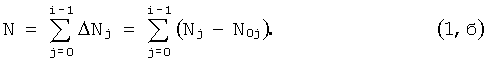
Сканирование угла поворота фазы φi преобразуют в код N пропорционально тактовым импульсам частотой F0 за интервал времени τj (см. фиг.1). Это соответствует времени от начала регистрации реверсивного приращения фазы Δφj (фиг.1, б) до его обнуления. Алгоритм последовательного приближения соответствует алгебраическому суммированию реверсивных приращений ΔNj=Nj-N0j фазы Δφj, регистрируемых в виде разницы ΔNj между измеряемым Nj и нормированным N0j значениями. Сумма реверсных значений в соответствии с алгоритмом 1,а может быть представлена какScanning the angle of rotation of the phase φ i is converted into code N in proportion to the clock pulses of frequency F 0 for the time interval τ j (see figure 1). This corresponds to the time from the beginning of the registration of the reverse phase increment Δφ j (Fig. 1, b) to its zeroing. The sequential approximation algorithm corresponds to the algebraic summation of the reverse increments ΔN j = N j -N 0j of the phase Δφ j , recorded as the difference ΔN j between the measured N j and the normalized N 0j values. The sum of the reverse values in accordance with algorithm 1, and can be represented as
Учитывая, что код N=F0t, т.е. произведение тактовой частоты F0 на время t, связанными с фиксированными интервалами T0 числом j импульсов, находим для последовательного приближения (фиг.1) ΔNj=N0.Given that the code N = F 0 t, i.e. the product of the clock frequency F 0 and time t associated with fixed intervals T 0 by the number j of pulses, we find for successive approximation (Fig. 1) ΔN j = N 0 .
Соответственно сумма приращений равнаAccordingly, the sum of the increments is
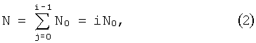
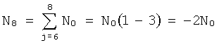
т.е. пропорциональна числу i импульсов. Графики на фиг.1, б, в иллюстрируют изменение кода на интервалах tj приращения ![]()
![]()
и реверса с 3 до -2, для ![]()
![]()
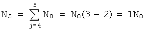
и ![]()
![]()
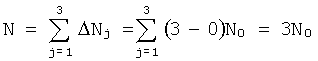
Максимальный код Nm определяется суммой - m i-тых сегментов ![]()
![]()
![]()
![]()
из m многофазных углов поворота с нормированной фазой φ0=φ2π/2m=φπ/m.of m multiphase rotation angles with normalized phase φ 0 = φ 2π / 2m = φ π / m.
Кольцо кругового сканера (см. фиг.3, в) разделено пополам на фазы сегментов φ правого φ+ и левого φ- поворота с возможностью вращения видеокамеры 1 в азимутальной плоскости по i-фазному углу поворота φ=iφ0 видеоизображения, поэтому коды N и Nm пропорциональны числу сегментов фаз, соответственно i и m:The ring scanner ring (see Fig. 3, c) is divided in half into phases of the segments φ of the right φ + and left φ - rotation with the possibility of rotating the camera 1 in the azimuthal plane along the i-phase angle of rotation φ = iφ 0 of the video image, therefore, the codes N and N m are proportional to the number of phase segments, respectively i and m:

Из этих соотношений следуют зависимости N(φ) и N(i):From these relations the dependences N (φ) and N (i) follow:
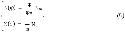
показывающие прямую зависимость кода N от угла поворота (фазы) φ и числа i сегментов.showing the direct dependence of the code N on the rotation angle (phase) φ and the number i of segments.
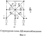
Структурная схема детектора движения (ДД) 2 (Фиг.4) поясняет способ видеонаблюдения. ДД 2 многофазного угла φ поворота содержит приемник излучения из ИК-фото диодной матрицы с 2m+1 фотодиодами Dj и D-j, ![]()
![]()
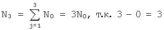
В исходном состоянии (см. фиг.3, б, в) объект 4 находится перпендикулярно оси видеосъемки видеокамеры 1, при этом в выходной диагонали коммутатора детектора движения 2 ток отсутствует (фиг.3, г), т.к. от излучателя ИК-светодиода D, расположенного на объекте 4 видеонаблюдения, лучи воздействуют на нулевой D0 фотодиод. В исходном состоянии код N детектора 2 равен нулю. При повороте объекта 4 вправо, например на 3 сегмента угла поворота φ=3φ0, код N=3N0, а нормированный код N0j=0N0 (см. фиг.3, в). Лучи от светодиода D объекта 4 регистрируются D3 фотодиодом, что увеличивает суммарный код детектора 2 в течение j тактов импульсами F0. За счет последовательного приближения нормируемого кода N0j к текущему Nj сканер (см. фиг.3, в) вращается вправо от j=3-го сегмента к нулевому (см. фиг.3, б), а код детектора 2 увеличиваетсяIn the initial state (see Fig. 3, b, c) the object 4 is perpendicular to the axis of the video recording of the camera 1, while there is no current in the output diagonal of the switch of the motion detector 2 (Fig. 3, d), because from the emitter of the infrared LED D, located on the object 4 of the video surveillance, the rays act on the zero D 0 photodiode. In the initial state, the code N of
Когда нулевой сегмент с фотодиодом Do окажется в азимутальной плоскости на оси, перпендикулярной ИК-светодиоду D объекта 4, детектор 2 привода 3 отключается, а объект 4 видеосъемки вновь оказывается перед объективом видеокамеры 1 на оси, перпендикулярной видеосъемке. Аналогично детектор движения 2 отслеживает левый поворот за счет включения D-j фотодиодов, что соответствует уменьшению кода в детекторе 2 импульсами частоты F0. Следовательно, ДД 2 регистрирует код N, пропорциональный интегралу (1) приращений ΔNj кода, соответствующих линейному преобразованию фазы φ=iφ0 (или числу i-сегментов) в код по характеристикам (5).When the zero segment with the photodiode D o is in the azimuthal plane on the axis perpendicular to the IR LED D of the object 4, the
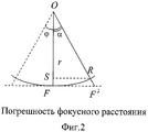
Оценим предлагаемое решение в сравнении с прототипом по метрологической эффективности, а именно точности (четкости) изображения объекта видеосъемки, которое определяется погрешностью фокусного расстояния (см. фиг.3).Let us evaluate the proposed solution in comparison with the prototype in terms of metrological efficiency, namely, the accuracy (clarity) of the image of the video object, which is determined by the focal length error (see Fig. 3).
Фокусное расстояние от центра О объектива до объекта F равно кратчайшему расстоянию OF окружности радиусом r для объекта, находящегося в фокусе видеосъемки. При перемещении объекта вправо (или влево), т.е. по касательной к фокусному расстоянию r, его радиус увеличивается до окружности с радиусом R - отрезок OF′. Погрешность ε изменения фокусного расстояния определяется относительным изменением радиусов Δ=r-R к нормированному фокусу r исходной окружностиThe focal length from the center O of the lens to the object F is equal to the shortest distance OF of a circle of radius r for an object in focus of the video. When moving an object to the right (or left), i.e. tangent to the focal length r, its radius increases to a circle with radius R - segment OF ′. The error ε of the change in the focal length is determined by the relative change in the radii Δ = r-R to the normalized focus r of the original circle
![]()
![]()
Отношение R/r радиусов окружностей несложно найти из соотношения сторон подобных треугольников FOF′ и SOR с равным углом α, соответствующим половине фазы φ/2 угла φ поворота в азимутальной плоскости перемещения объекта видеонаблюдения:The ratio R / r of the radii of the circles is easy to find from the ratio of the sides of similar triangles FOF ′ and SOR with an equal angle α corresponding to half of the phase φ / 2 of the rotation angle φ in the azimuthal plane of movement of the video surveillance object:
![]()
![]()
т.к. катет OS прямоугольного треугольника SOR находится из определения cosα=OS/r, a OS/r=r/R следует из подобия треугольников. За нормированную фазу φ0 целесообразно принять угол поворота с погрешностью фокусного расстояния, например 1%, т.е. ε=0,01 или φ0=φ(0,01). Нормированную фазу φ0 также можно определить из половины окружности с углом φm=π=180° и максимального числа m сегментов ibecause the leg OS of the right triangle SOR is found from the definition cosα = OS / r, and OS / r = r / R follows from the similarity of triangles. For the normalized phase φ 0, it is advisable to take the angle of rotation with an accuracy of the focal length, for example 1%, i.e. ε = 0.01 or φ 0 = φ (0.01). The normalized phase φ 0 can also be determined from a half circle with an angle φ m = π = 180 ° and a maximum number m of segments i
φ0=π/2m.φ 0 = π / 2m.
Для многофазного угла поворота φ=i·φ0 из i сегментов, где ![]()
![]()
ε=1-1/cos(iπ/2m).ε = 1-1 / cos (iπ / 2m).
Оценка погрешности ε(φ) с нормированной фазой φ0/2=8° и максимумом m=11 сегментов сведена в таблицу для ![]()
![]()
Нижняя строка таблицы отражает погрешность εr фокусировки при перемещении объекта по кругу с радиусом r фокусного расстояния, которой соответствует оценкаThe bottom row of the table reflects the error ε r of focusing when moving an object in a circle with a radius r of focal length, which corresponds to the estimate
εr=1-cos(iπ/2m).ε r = 1-cos (iπ / 2m).
Погрешности ε и εr совпадают при небольших (стандартных) углах ![]()
![]()
![]()
![]()
![]()
![]()
Таким образом, предлагаемые способ и устройство оптико-электронного кругового обзора, в отличие от известных решений, за счет автоматизации вращения угла поворота позволяют расширить видеонаблюдение до кругового панорамного обзора с регламентируемой точностью нормируемой меры, например, с погрешностью 1% для видеообъектива с углом 16°, что на два порядка повышает точность видеонаблюдения или метрологическую эффективность видеосъемки. Предлагаемые способ и устройство расширяют возможности бытовой видеотехники до профессионального уровня за счет внедрения измерительной и информационной техники в оптико-электронное приборостроение.Thus, the proposed method and device of optoelectronic circular viewing, in contrast to the known solutions, by automating rotation of the rotation angle, can extend video surveillance to a panoramic panoramic view with regulated accuracy of the standardized measure, for example, with an error of 1% for a video lens with an angle of 16 ° , which increases the accuracy of video surveillance by two orders of magnitude or the metrological effectiveness of video recording. The proposed method and device expand the capabilities of household video equipment to a professional level through the introduction of measuring and information technology in optoelectronic instrumentation.
Claims (5)
Priority Applications (1)
| Application Number | Priority Date | Filing Date | Title |
|---|---|---|---|
| RU2010114957/09A RU2425392C1 (en) | 2010-04-14 | 2010-04-14 | Method and device for optoelectronic all-round view |
Applications Claiming Priority (1)
| Application Number | Priority Date | Filing Date | Title |
|---|---|---|---|
| RU2010114957/09A RU2425392C1 (en) | 2010-04-14 | 2010-04-14 | Method and device for optoelectronic all-round view |
Publications (1)
| Publication Number | Publication Date |
|---|---|
| RU2425392C1 true RU2425392C1 (en) | 2011-07-27 |
Family
ID=44753682
Family Applications (1)
| Application Number | Title | Priority Date | Filing Date |
|---|---|---|---|
| RU2010114957/09A RU2425392C1 (en) | 2010-04-14 | 2010-04-14 | Method and device for optoelectronic all-round view |
Country Status (1)
| Country | Link |
|---|---|
| RU (1) | RU2425392C1 (en) |
Citations (6)
| Publication number | Priority date | Publication date | Assignee | Title |
|---|---|---|---|---|
| US4275399A (en) * | 1979-08-02 | 1981-06-23 | Hughes Aircraft Company | Apparatus for determining the direction of arrival of applied energy |
| US6031605A (en) * | 1995-03-28 | 2000-02-29 | Hollandse Signaalapparaten B.V. | Arrangement for the detection of targets |
| WO2007132033A1 (en) * | 2006-05-17 | 2007-11-22 | Smart Technology, S.A. | System for detecting, guiding or tracking devices or persons |
| RU2321016C1 (en) * | 2006-05-24 | 2008-03-27 | Федеральное государственное унитарное предприятие "Производственное объединение "Уральский оптико-механический завод" | Circular view electro-optic device |
| RU2356063C1 (en) * | 2007-11-27 | 2009-05-20 | Открытое акционерное общество Центральный научно-исследовательский институт "ЦИКЛОН" | All-around view optical-navigation system |
| RU88814U1 (en) * | 2009-09-02 | 2009-11-20 | Общество с ограниченной ответственностью Научно-производственная компания "ФаворитЪ" | OPTICAL-ELECTRONIC MODULE "FOCUS-D" |
-
2010
- 2010-04-14 RU RU2010114957/09A patent/RU2425392C1/en not_active IP Right Cessation
Patent Citations (6)
| Publication number | Priority date | Publication date | Assignee | Title |
|---|---|---|---|---|
| US4275399A (en) * | 1979-08-02 | 1981-06-23 | Hughes Aircraft Company | Apparatus for determining the direction of arrival of applied energy |
| US6031605A (en) * | 1995-03-28 | 2000-02-29 | Hollandse Signaalapparaten B.V. | Arrangement for the detection of targets |
| WO2007132033A1 (en) * | 2006-05-17 | 2007-11-22 | Smart Technology, S.A. | System for detecting, guiding or tracking devices or persons |
| RU2321016C1 (en) * | 2006-05-24 | 2008-03-27 | Федеральное государственное унитарное предприятие "Производственное объединение "Уральский оптико-механический завод" | Circular view electro-optic device |
| RU2356063C1 (en) * | 2007-11-27 | 2009-05-20 | Открытое акционерное общество Центральный научно-исследовательский институт "ЦИКЛОН" | All-around view optical-navigation system |
| RU88814U1 (en) * | 2009-09-02 | 2009-11-20 | Общество с ограниченной ответственностью Научно-производственная компания "ФаворитЪ" | OPTICAL-ELECTRONIC MODULE "FOCUS-D" |
Similar Documents
| Publication | Publication Date | Title |
|---|---|---|
| US9906737B2 (en) | Co-aperture multi-FOV image-spectrum cooperative detection system and method | |
| CN110440926B (en) | Time-sharing infrared polarization imaging device and method for dynamic target measurement | |
| US20200111335A1 (en) | Infrared motion sensing device and method | |
| US9127942B1 (en) | Surface distance determination using time-of-flight of light | |
| CN110726383B (en) | A high-precision integrated three-dimensional measurement system based on MEMS | |
| CN104469110A (en) | Light field collecting device with changeable angle sampling number | |
| CN102507148A (en) | Detection system of multi-quadrant photoelectric detector | |
| US10027914B2 (en) | Circuits for self-powered image sensors | |
| US9562966B1 (en) | Surface distance determination using reflected light | |
| US4341447A (en) | Infrared camera ranging system | |
| Sher et al. | Low intensity LiDAR using compressed sensing and a photon number resolving detector | |
| RU2425392C1 (en) | Method and device for optoelectronic all-round view | |
| US3859460A (en) | Passive image stabilization system | |
| RU2436255C2 (en) | Video surveillance method and apparatus | |
| KR20200037699A (en) | Thermal-infrared temperature measurement apparatus for monitoring photovoltaic solar panel and measurement method thereof | |
| CN103487917A (en) | Multifunctional lens with multiple image collecting heads | |
| CN209296005U (en) | Unmanned plane indoor locating system for nuclear power station | |
| CN112924987B (en) | A laser light field visualization device and method based on an InGaAs camera | |
| Laukkanen | Performance evaluation of time-of-flight depth cameras | |
| Breiter et al. | MCT SWIR modules for active imaging | |
| CN204758840U (en) | Portable double vision field thermal imaging observation device | |
| Maas | Close range photogrammetry sensors | |
| CN110456368A (en) | A kind of infrared ranging system and its distance measuring method | |
| Shoani et al. | Determining subject distance based on face size | |
| RU2573245C2 (en) | Method for contactless control using polarisation marker and system therefor |
Legal Events
| Date | Code | Title | Description |
|---|---|---|---|
| MM4A | The patent is invalid due to non-payment of fees |
Effective date: 20150415 |