RU2425398C1 - Magnetic induction measuring transducer - Google Patents
Magnetic induction measuring transducer Download PDFInfo
- Publication number
- RU2425398C1 RU2425398C1 RU2009146591/28A RU2009146591A RU2425398C1 RU 2425398 C1 RU2425398 C1 RU 2425398C1 RU 2009146591/28 A RU2009146591/28 A RU 2009146591/28A RU 2009146591 A RU2009146591 A RU 2009146591A RU 2425398 C1 RU2425398 C1 RU 2425398C1
- Authority
- RU
- Russia
- Prior art keywords
- code
- magnetic induction
- differential amplifier
- controlled
- windings
- Prior art date
Links
Images
Landscapes
- Arrangements For Transmission Of Measured Signals (AREA)
- Geophysics And Detection Of Objects (AREA)
Abstract
Description
Изобретение относится к устройствам измерения магнитной индукции переменного электромагнитного поля в диапазоне частот от единиц герц до 1 МГц. Преимущественные применения - электроразведка, использующая гармонические магнитные поля: индукционные частотные и дистанционные зондирования, дипольное электромагнитное профилирование.The invention relates to devices for measuring the magnetic induction of an alternating electromagnetic field in the frequency range from units of hertz to 1 MHz. Preferred applications are electrical exploration using harmonic magnetic fields: induction frequency and remote sensing, dipole electromagnetic profiling.
Известен магнитоиндукционный преобразователь (МИП) [1], содержащий многовитковую рамку на ферритовом сердечнике. Выходное напряжение МИП поступает по подводящему кабелю на вход цифрового микровольтметра. Существенным недостатком известного преобразователя является значительное влияние паразитных емкостей подводящего кабеля при повышении рабочей частоты.Known magnetic induction Converter (MIP) [1] containing a multi-turn frame on a ferrite core. The output voltage of the MIP is supplied through the supply cable to the input of a digital microvoltmeter. A significant disadvantage of the known Converter is the significant influence of stray capacitance of the supply cable with increasing operating frequency.
Известен также измерительный преобразователь магнитной индукции [2], состоящий из индукционного измерительного преобразователя и нагруженного на измерительную цепь. Существенным недостатком этого преобразователя, как и [1], является значительное влияние паразитных емкостей подводящего кабеля при повышении рабочей частоты.Also known is a magnetic induction measuring transducer [2], consisting of an induction measuring transducer and loaded onto the measuring circuit. A significant drawback of this converter, as well as [1], is the significant influence of stray capacitance of the supply cable with increasing operating frequency.
Наиболее близким техническим решением является малогабаритный индукционный преобразователь [3], взятый нами в качестве устройства-прототипа. Устройство-прототип состоит из воздушной многовитковой петли, выходы и средняя точка которой соединены с входами и "землей" (общая шина) предварительного усилителя, подключенного к измерителю. Основным достоинством устройства-прототипа является уменьшение влияния магнитной (поперечной помехи) и электрической (продольной помехи) наводок за счет введения в схему высокочастотного индукционного фильтра.The closest technical solution is a small-sized induction converter [3], which we took as a prototype device. The prototype device consists of an air multi-turn loop, the outputs and the midpoint of which are connected to the inputs and the ground (common bus) of the pre-amplifier connected to the meter. The main advantage of the prototype device is to reduce the effects of magnetic (transverse interference) and electrical (longitudinal interference) interference due to the introduction of a high-frequency induction filter into the circuit.
Однако устройство-прототип имеет существенные недостатки:However, the prototype device has significant disadvantages:
1. Значительные габаритные размеры (до единиц метров) приемной петли.1. Significant overall dimensions (up to units of meters) of the receiving loop.
2. Значительные паразитные емкости приемной петли, что не позволяет расширение рабочих частот в область высоких частот.2. Significant parasitic capacitance of the receiving loop, which does not allow the expansion of the operating frequencies in the high frequency region.
3. Значительное влияние паразитной емкости подводящих проводов от приемной петли к измерительному устройству. Паразитная емкость сужает частотный диапазон.3. Significant influence of stray capacitance of the lead wires from the receiving loop to the measuring device. Spurious capacitance narrows the frequency range.
4. Обеспечивает преобразование только вертикальной составляющей магнитной индукции.4. Provides conversion of only the vertical component of magnetic induction.
Цель предлагаемого изобретения - расширение рабочего частотного диапазона и повышение стабильности коэффициента преобразования К (В/нТл*Гц) предлагаемого технического устройства.The purpose of the invention is to expand the operating frequency range and increase the stability of the conversion coefficient K (V / nTl * Hz) of the proposed technical device.
Поставленная цель достигается тем, что в измерительный преобразователь магнитной индукции, содержащий магнитоиндукционный датчик, состоящий из двух обмоток, соединенных последовательно и подключенных к входам дифференциального усилителя, дополнительно введен кодоуправляемый магазин емкостей, подключенный к обмоткам и к входам дифференциального усилителя, причем выход кодоуправляемого магазина емкостей подключен двумя ключами к каждой емкости, входящей в кодоуправляемый магазин емкостей, а кроме того, магнитоиндукционный датчик, кодоуправляемый магазин емкостей и дифференциальный усилитель выполнены в виде вытянутой жесткой конструкции.This goal is achieved by the fact that in the magnetic induction measuring transducer containing a magnetic induction sensor, consisting of two windings connected in series and connected to the inputs of the differential amplifier, an additional code-controlled capacitance magazine is connected, connected to the windings and the inputs of the differential amplifier, and the output of the code-controlled capacitance store connected by two keys to each capacity included in the code-controlled capacity store, and in addition, a magnetic induction sensor, to one-manned capacity magazine and differential amplifier are made in the form of an elongated rigid structure.
На фиг.1 изображена структурная схема предлагаемого устройства.Figure 1 shows the structural diagram of the proposed device.
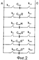
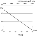
На фиг.2 представлена схема кодоуправляемого магазина емкостей от Cmax/215 до 2*Cmax. На фиг.3 приведена зависимость частоты от величины настраиваемой емкости и пропорциональная управляющему коду емкости.Figure 2 presents a diagram of a code-controlled store capacity from Cmax / 2 15 to 2 * Cmax. Figure 3 shows the dependence of the frequency on the value of the adjustable capacitance and proportional to the control code of the capacitance.
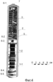
На фиг.4 дан общий вид разработанного измерительного преобразователя магнитной индукции на восемь рабочих: 125 Гц, 500 Гц, 1 кГц, 2 кГц, 4 кГц, 8 кГц, 16 кГц.Figure 4 is a General view of the developed measuring transducer of magnetic induction for eight workers: 125 Hz, 500 Hz, 1 kHz, 2 kHz, 4 kHz, 8 kHz, 16 kHz.
Предлагаемое устройство (фиг.1) содержит магнитоиндукционный датчик (МИД) 1, состоящий из двух обмоток 1-1 и 1-2, соединенных последовательно, дифференциальный усилитель 2 и кодоуправляемый магазин емкостей 3.The proposed device (figure 1) contains a magnetic induction sensor (MID) 1, consisting of two windings 1-1 and 1-2, connected in series, a
Блок обработки информации 4 не входит в предлагаемое техническое решение и приведен только для пояснения работы предлагаемого устройства.The
Предлагаемое устройство (фиг.1) работает следующим образом. Измеряемая магнитная индукция В=Bm·sin(ω0·t+φ0) направлена вдоль магнитоиндукционного датчика (МИД) 1-1 и 1-2 (фиг.1), где Bm, ω0, φ0 соответственно амплитуда, частота и фазовый сдвиг. Выходное напряжение обмоток МИД 1 определяется следующим выражением:The proposed device (figure 1) works as follows. The measured magnetic induction B = B m · sin (ω 0 · t + φ 0 ) is directed along the magnetic induction sensor (MID) 1-1 and 1-2 (figure 1), where B m , ω 0 , φ 0, respectively, the amplitude, frequency and phase shift. The output voltage of the windings MID 1 is determined by the following expression:


где К=ω0·W·µT·µ0·S, где W - количество витков, S - площадь одного витка, µT - относительная магнитная проницаемость, µ0=4π·10-7 Гн/м.where K = ω 0 · W · μ T · μ 0 · S, where W is the number of turns, S is the area of one turn, μ T is the relative magnetic permeability, μ 0 = 4π · 10 -7 GN / m.
Параллельно обмоткам МИД 1 подключается кодоуправляемый магазин емкостей 3. Величина емкости задается из условия:In parallel to the windings of MID 1, a code-controlled
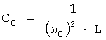
где L - индуктивность магнитоиндукционного датчика, т.е. контур, состоящий из двух обмоток и конденсатор С0, настраивается в резонанс.where L is the inductance of the magnetic induction sensor, i.e. a circuit consisting of two windings and a capacitor C 0 is tuned to resonance.
Тогда выходные напряжения обмоток определяется выражением:Then the output voltage of the windings is determined by the expression:
U1p=-K·Q·Bm·cos(ω0·t+φ0)U 1p = -K · Q · B m · cos (ω 0 · t + φ 0 )
U2p=K·Q·Bm·cos(ω0·t+φ0)U 2p = K · Q · B m · cos (ω 0 · t + φ 0 )
где Q - эквивалентная добротность контура с учетом входных сопротивлений дифференциального усилителя 2.where Q is the equivalent Q factor of the circuit, taking into account the input resistances of
Эти напряжения подаются на инвертирующий и не инвертирующий входы дифференциального усилителя. Выходное напряжение дифференциального усилителя без учета входного сопротивления дифференциального усилителя определяется выражениемThese voltages are applied to the inverting and non-inverting inputs of the differential amplifier. The output voltage of the differential amplifier without taking into account the input resistance of the differential amplifier is determined by the expression
Uвых=2·К·Ку·Q·Bm·cos(ω0·t+φ0)U out =
где Ку - коэффициент усиления дифференциального усилителя 2.where K y is the gain of the
Выходное напряжение усилителя 2 поступает на блок обработки информации 4. Блок 4 также задает управляющий код для кодоуправляемого магазина емкостей 3 по n - управляющим жилам (фиг.1).The output voltage of the
Структурная схема кодоуправляемого магазина емкостей изображена на фиг.3 переменная емкость задается как C=f(N) путем задания соответствующего управляющего кода N (фиг.3) и подключения к входу блока 3 (фиг.1, 4) соответствующих конденсаторов с переменной емкостью Спер=Cmax/2i-1, где i=1,2…16. У каждого конденсатора имеется два ключа Ki-1 и Ki-2 для подключения к выходу блока 3 (фиг.1).The block diagram of the code-controlled capacity magazine is shown in Fig. 3; the variable capacitance is set as C = f (N) by setting the corresponding control code N (Fig. 3) and connecting the corresponding capacitors with variable capacitance C to the input of block 3 (Figs. 1, 4) per = C max / 2 i-1 , where i = 1,2 ... 16. Each capacitor has two keys K i-1 and K i-2 for connecting to the output of block 3 (figure 1).
Применение двух ключей обеспечивает устранение емкостной ассиметрии выводов кодоуправляемого магазина емкостей 2 (фиг.2) относительно общей точки соединения МИД 1 и дифференциального усилителя 2(фиг.1). Емкостная ассиметрия возникает при применении для подключения одного ключа каждого конденсатора и соединения в одну точку всех вторых выводов конденсаторов кодоуправляемого магазина емкостей 3.The use of two keys ensures the elimination of capacitive asymmetry of the conclusions of the code-controlled store of capacities 2 (FIG. 2) with respect to the common connection point of MID 1 and differential amplifier 2 (FIG. 1). Capacitive asymmetry occurs when each capacitor is used to connect one key and connect all second terminals of the capacitors of the code-controlled store of
Емкостная ассиметрия особенно велика при малых значениях емкости, включаемой в колебательный контур. Влияние этой ассиметрии значительно в высокочастотной области рабочего диапазона частот и вызывает изменение коэффициента усиления дифференциального усилителя (фиг.1).Capacitive asymmetry is especially large for small values of the capacitance included in the oscillatory circuit. The influence of this asymmetry is significant in the high-frequency region of the operating frequency range and causes a change in the gain of the differential amplifier (Fig. 1).
Конструктивно предлагаемое устройство выполнено в виде цельного моноблока, помещенного в защитную трубу 5 (фиг.4). Все блоки в этой трубе вытянуты вдоль трубы 4. Блоки 1-3 (фиг.1) устройства в трубе 5 жестко фиксируются с помощью непроводящих колец 6-1-6-5 (фиг.4), имеющих внешний диаметр, равный внутреннему диаметру защитной трубы 5. Для подключения предлагаемого устройства к блоку обработки информации на внешней стороне непроводящего кольца 6-1 располагается разъем 7 (фиг.4).Structurally, the proposed device is made in the form of a solid candy bar, placed in a protective pipe 5 (figure 4). All the blocks in this pipe are elongated along the
Предлагаемое устройство было использовано в качестве измерительного преобразователя магнитной индукции на восьми частотах: 125 Гц*2p-1, где р=1,2…8 в аппаратуре для малоглубинных зондирований МЧ3-8. В предлагаемом устройстве удалось расширить на порядок рабочий частотный диапазон, а также повысить временную стабильность коэффициента преобразования.The proposed device was used as a measuring transducer of magnetic induction at eight frequencies: 125 Hz * 2 p-1 , where p = 1.2 ... 8 in the equipment for shallow sounding MCH3-8. In the proposed device, it was possible to expand by an order of magnitude the working frequency range, as well as to increase the temporal stability of the conversion coefficient.
Предлагаемое устройство испытано в полевых условиях в районах с высоким уровнем электромагнитных помех.The proposed device is tested in the field in areas with a high level of electromagnetic interference.
Таким образом, в предлагаемом устройстве обеспечено расширение частотного диапазона и повышена стабильность коэффициента преобразования магнитной индукции в электрический сигнал.Thus, in the proposed device, the expansion of the frequency range is provided and the stability of the coefficient of conversion of magnetic induction into an electrical signal is increased.
ЛитератураLiterature
1. Методические рекомендации по методу заряда с много компонентными измерениями на рудных месторождениях. - Октябрьский: ВНИИГИС, 1991, с.50-52.1. Methodological recommendations on the method of charge with multi-component measurements in ore deposits. - October: VNIIGIS, 1991, p. 50-52.
2. Г.В.Абрамзон, Ю.П.Обоишев. Индукционные измерительные преобразователи переменных магнитных полей. Л., Энергоатомиздат, 1984; с.18-22.2. G.V. Abramzon, Yu.P. Oboishev. Induction measuring transducers of variable magnetic fields. L., Energoatomizdat, 1984; p. 18-22.
3. А.К.Захаркин. Малогабаритный индукционный преобразователь. Патент России №2073257 от 23.08.1993 г. (прототип).3. A.K. Zakharkin. Small induction converter. Russian patent No. 2073257 from 08.23.1993 (prototype).
Claims (1)
Priority Applications (1)
| Application Number | Priority Date | Filing Date | Title |
|---|---|---|---|
| RU2009146591/28A RU2425398C1 (en) | 2009-12-15 | 2009-12-15 | Magnetic induction measuring transducer |
Applications Claiming Priority (1)
| Application Number | Priority Date | Filing Date | Title |
|---|---|---|---|
| RU2009146591/28A RU2425398C1 (en) | 2009-12-15 | 2009-12-15 | Magnetic induction measuring transducer |
Publications (2)
| Publication Number | Publication Date |
|---|---|
| RU2009146591A RU2009146591A (en) | 2011-06-20 |
| RU2425398C1 true RU2425398C1 (en) | 2011-07-27 |
Family
ID=44737611
Family Applications (1)
| Application Number | Title | Priority Date | Filing Date |
|---|---|---|---|
| RU2009146591/28A RU2425398C1 (en) | 2009-12-15 | 2009-12-15 | Magnetic induction measuring transducer |
Country Status (1)
| Country | Link |
|---|---|
| RU (1) | RU2425398C1 (en) |
Citations (4)
| Publication number | Priority date | Publication date | Assignee | Title |
|---|---|---|---|---|
| SU1762248A1 (en) * | 1990-01-22 | 1992-09-15 | Дальневосточный политехнический институт им.В.В.Куйбышева | Measuring converter of alternating current |
| CN2681150Y (en) * | 2004-03-05 | 2005-02-23 | 马晓武 | Eddy current type seismic wave detection device |
| CN201035156Y (en) * | 2007-04-10 | 2008-03-12 | 上海凯歌电子有限公司 | Metal detector and its sensor |
| WO2008073375A2 (en) * | 2006-12-11 | 2008-06-19 | Quasar Federal Systems, Inc. | Compact underwater electromagnetic measurement system |
-
2009
- 2009-12-15 RU RU2009146591/28A patent/RU2425398C1/en not_active IP Right Cessation
Patent Citations (4)
| Publication number | Priority date | Publication date | Assignee | Title |
|---|---|---|---|---|
| SU1762248A1 (en) * | 1990-01-22 | 1992-09-15 | Дальневосточный политехнический институт им.В.В.Куйбышева | Measuring converter of alternating current |
| CN2681150Y (en) * | 2004-03-05 | 2005-02-23 | 马晓武 | Eddy current type seismic wave detection device |
| WO2008073375A2 (en) * | 2006-12-11 | 2008-06-19 | Quasar Federal Systems, Inc. | Compact underwater electromagnetic measurement system |
| CN201035156Y (en) * | 2007-04-10 | 2008-03-12 | 上海凯歌电子有限公司 | Metal detector and its sensor |
Also Published As
| Publication number | Publication date |
|---|---|
| RU2009146591A (en) | 2011-06-20 |
Similar Documents
| Publication | Publication Date | Title |
|---|---|---|
| US3851242A (en) | Frequency-modulated eddy-current proximity gage | |
| EP0465568B1 (en) | Double tuned bird cage coil | |
| CN104061969B (en) | A kind of capacitance-type electromagnetic flow signal adapter | |
| CN103900661A (en) | Segmented liquid level sensor based on capacitance-to-digital conversion technology | |
| CN115184849B (en) | High-resolution magnetic field measuring device based on NMR probe | |
| CN107941660B (en) | A kind of the error extracting method and device of magnetic particle detection system | |
| CN109917193A (en) | A kind of dielectric constant measuring apparatus | |
| CN102252795B (en) | A capacitive cable force sensor | |
| RU2425398C1 (en) | Magnetic induction measuring transducer | |
| CN107607893A (en) | A kind of design method of high flat degree medium-high magnetic field measuring coil | |
| RU2030713C1 (en) | Electromagnetic flow meter | |
| US3840805A (en) | Device for measuring parameters of resonant lc-circuit | |
| RU2265816C2 (en) | Tool-defectoscope for detecting openings in pipeline | |
| CN109580765A (en) | A kind of anti-interference biphase gas and liquid flow measuring of phase ratio method of high-responsivity | |
| RU2221988C1 (en) | Variable-induction displacement pickup | |
| RU2419763C1 (en) | Vortex current calliper | |
| CN108226279A (en) | Towards the special fluxgate detector of buried corrosion pipeline | |
| RU2194242C2 (en) | Device for building output signal of inductive differential measurement transducer | |
| JPS607371A (en) | Apparatus for measuring capacity and resistance of highly stable superlow impedance with wide frequency range | |
| RU2087927C1 (en) | Geological survey measuring device | |
| CN212693887U (en) | Model circuit and measuring device for inversion of distributed parameters of densely wound coils | |
| KR100361167B1 (en) | A measurement system for initial permeability | |
| CN203965376U (en) | A kind of frequency measurement is surveyed the device of Measurement for Grain Moisture Content | |
| RU2708938C1 (en) | Device for measuring high pressures of gaseous media | |
| SU1645920A1 (en) | Capacitance converter |
Legal Events
| Date | Code | Title | Description |
|---|---|---|---|
| MM4A | The patent is invalid due to non-payment of fees |
Effective date: 20181216 |