RU2425409C2 - Method of controlling movement of flight simulator and flight simulator implementing said method - Google Patents
Method of controlling movement of flight simulator and flight simulator implementing said method Download PDFInfo
- Publication number
- RU2425409C2 RU2425409C2 RU2008118206/08A RU2008118206A RU2425409C2 RU 2425409 C2 RU2425409 C2 RU 2425409C2 RU 2008118206/08 A RU2008118206/08 A RU 2008118206/08A RU 2008118206 A RU2008118206 A RU 2008118206A RU 2425409 C2 RU2425409 C2 RU 2425409C2
- Authority
- RU
- Russia
- Prior art keywords
- roll
- simulator
- pilot
- angular
- component
- Prior art date
Links
Images





Classifications
-
- G—PHYSICS
- G09—EDUCATION; CRYPTOGRAPHY; DISPLAY; ADVERTISING; SEALS
- G09B—EDUCATIONAL OR DEMONSTRATION APPLIANCES; APPLIANCES FOR TEACHING, OR COMMUNICATING WITH, THE BLIND, DEAF OR MUTE; MODELS; PLANETARIA; GLOBES; MAPS; DIAGRAMS
- G09B9/00—Simulators for teaching or training purposes
- G09B9/02—Simulators for teaching or training purposes for teaching control of vehicles or other craft
- G09B9/08—Simulators for teaching or training purposes for teaching control of vehicles or other craft for teaching control of aircraft, e.g. Link trainer
- G09B9/12—Motion systems for aircraft simulators
-
- G—PHYSICS
- G05—CONTROLLING; REGULATING
- G05B—CONTROL OR REGULATING SYSTEMS IN GENERAL; FUNCTIONAL ELEMENTS OF SUCH SYSTEMS; MONITORING OR TESTING ARRANGEMENTS FOR SUCH SYSTEMS OR ELEMENTS
- G05B19/00—Program-control systems
- G05B19/02—Program-control systems electric
- G05B19/18—Numerical control [NC], i.e. automatically operating machines, in particular machine tools, e.g. in a manufacturing environment, so as to execute positioning, movement or co-ordinated operations by means of program data in numerical form
- G05B19/408—Numerical control [NC], i.e. automatically operating machines, in particular machine tools, e.g. in a manufacturing environment, so as to execute positioning, movement or co-ordinated operations by means of program data in numerical form characterised by data handling or data format, e.g. reading, buffering or conversion of data
- G05B19/4086—Coordinate conversions; Other special calculations
Landscapes
- Engineering & Computer Science (AREA)
- General Physics & Mathematics (AREA)
- Theoretical Computer Science (AREA)
- Physics & Mathematics (AREA)
- Aviation & Aerospace Engineering (AREA)
- Automation & Control Theory (AREA)
- Manufacturing & Machinery (AREA)
- Human Computer Interaction (AREA)
- Business, Economics & Management (AREA)
- Educational Administration (AREA)
- Educational Technology (AREA)
- Control Of Position, Course, Altitude, Or Attitude Of Moving Bodies (AREA)
- Management, Administration, Business Operations System, And Electronic Commerce (AREA)
- Control Of Electric Motors In General (AREA)
Abstract
Description
Область техники, к которой относится изобретениеFIELD OF THE INVENTION
Настоящее изобретение относится к пилотажным тренажерам и способам управления пилотажными тренажерами.The present invention relates to flight simulators and methods for controlling flight simulators.
Уровень техникиState of the art
Системы подвижности пилотажных тренажеров, или, короче говоря, пилотажные тренажеры, представлены системами подвижности с 6-ю степенями свободы. Пилотажные тренажеры обеспечивают точность воспроизведения ощущений движения, обуславливаемых маневрами, посредством фильтрации угловых ускорений и (линейных) удельных сил. Эти сигналы важны для восприятия пилота, и поэтому движения пилотажных тренажеров должны быть согласованы с движениями реального летательного аппарата. В описаниях известных способов управления пилотажными тренажерами обнаружены следующие алгоритмы.The mobility systems of flight simulators, or, in short, flight simulators, are represented by mobility systems with 6 degrees of freedom. Flight simulators ensure the accuracy of reproducing the sensations of movement caused by maneuvers by filtering angular accelerations and (linear) specific forces. These signals are important for the perception of the pilot, and therefore the movements of the flight simulators must be consistent with the movements of a real aircraft. The following algorithms are found in the descriptions of known methods for controlling flight simulators.
Преобразование центроидаCentroid conversion
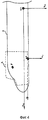
Поскольку сущность изобретения состоит в имитации движения, воспринимаемого пилотом, пилотажный тренажер гипотетически находится на летательном аппарате с соответствующей базисной точкой Р пилота (Фиг.4).Since the essence of the invention is to simulate the movement perceived by the pilot, the flight simulator is hypothetically located on the aircraft with the corresponding base point P of the pilot (Figure 4).
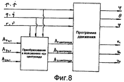
Нижеследующие логические рассуждения (Фиг.8) всегда учитываются в литературе (см. Russell V. Parrish, James Е. Dieudonne and Dennis J. Martin Jr., "Motion software for a synergistic six-degrees-of freedom motion base", p.9, NASA TN D-7350, декабрь 1973 / М.Baarspul, Delft University of Technology, "The generation of motion cues on a six-degrees-of freedom motion system", p.5, Report LR-248, июнь 1977 / G.A.J. van de Moesdijk, F.L. Van Biervliet, Delft University of Technology, "Investigation to improve the motion software of the Fokker F-28 flight simulator", p.4, Report LR-358, сентябрь 1982) и в практических приложениях.The following logical reasoning (Fig. 8) is always taken into account in the literature (see Russell V. Parrish, James E. Dieudonne and Dennis J. Martin Jr., "Motion software for a synergistic six-degrees-of freedom motion base", p. 9, NASA TN D-7350, December 1973 / M. Baarspul, Delft University of Technology, "The generation of motion cues on a six-degrees-of freedom motion system", p.5, Report LR-248, June 1977 / GAJ van de Moesdijk, FL Van Biervliet, Delft University of Technology, "Investigation to improve the motion software of the Fokker F-28 flight simulator", p. 4, Report LR-358, September 1982) and in practical applications.
Удельные силы вычисляются на летательном аппарате в месте нахождения центроида гипотетической платформы в соответствии с формулами, приведенными в нижеследующих первоисточниках: О.Н. Gerlach, Technische Hogeschool Delft, "Vliegeigenshappen 1", p.227, Dictaat D 26, октябрь-ноябрь 1981 / M.Baarspul, Delft University of Technology, "The generation of motion cues on a six-degrees-of freedom motion system", p.6, Report LR-248, июнь 1977.The specific forces are calculated on the aircraft at the location of the centroid of the hypothetical platform in accordance with the formulas given in the following primary sources: Gerlach, Technische Hogeschool Delft, "Vliegeigenshappen 1", p. 227, Dictaat D 26, October-November 1981 / M. Baarspul, Delft University of Technology, "The generation of motion cues on a six-degrees-of freedom motion system" , p.6, Report LR-248, June 1977.
Например, в направлении «у»:For example, in the direction of "y":

где Ау центроида - составляющая удельной силы вдоль оси «у» в гипотетическом месте нахождения центроида тренажера по отношению к системе координат летательного аппарата; Ау ц.т. - составляющая удельной силы вдоль оси «у» в центре тяжести летательного аппарата, р - угловая скорость крена; q - угловая скорость тангажа, r - угловая скорость рыскания, 

В программе движения в качестве входных сигналов используются три корректируемые составляющие удельной силы - Ах центроида, Ау центроида,The program of motion as input signals uses three adjustable components of the specific force - A x centroid , A at the centroid ,
Az центроида - и три угловые скорости р, q, r (или угловые ускорения). 6 выходных сигналов программы движения управляют положением (по 3-м координатам) центроида подвижной платформы, а также 3-мя углами Эйлера.A z of the centroid - and three angular velocities p, q, r (or angular accelerations). 6 output signals of the motion program control the position (in 3 coordinates) of the centroid of the moving platform, as well as 3 Euler angles.
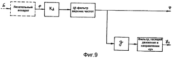
Имитация углового ускорения крена (Фиг.9)Simulation of angular acceleration of the roll (Fig.9)
Угловую скорость крена, умноженную на понижающий настроечный передаточный коэффициент Kd, фильтруют через фильтр верхних частот крена (1-го или 2-го порядка). Чтобы поддержать «выравнивание в соответствии с направлением силы тяжести» при определении координируемой траектории, используются поперечные качания. Для определения поперечного положения в пределах границ тренажера сигнал поперечного положения пропускают через фильтр, гасящий движение в направлении «y», в общем случае - 2-го порядка. Выходными сигналами программы являются угол φ крена тренажера и положение центроида вдоль оси «у».The angular velocity of the roll, multiplied by a lower tuning gear coefficient K d , is filtered through a high-pass filter of the roll (1st or 2nd order). To support “alignment according to the direction of gravity” in determining the coordinated path, lateral swings are used. To determine the transverse position within the boundaries of the simulator, the transverse position signal is passed through a filter that dampens the movement in the y direction, in the general case, of the second order. The output signals of the program are the angle φ of the heel of the simulator and the position of the centroid along the y axis.
Имитация поперечной удельной силы (Фиг.10)Simulation of the transverse specific gravity (Figure 10)
Поперечную удельную силу, вычисляемую в гипотетическом положении центроида, умножают на понижающий настроечный передаточный коэффициент, а затем посылают через два фильтра: позиционный ' фильтр верхних частот и угловой фильтр нижних частот. Эти фильтры в большинстве случаев являются фильтрами 2-го порядка и не комплементарными. Они также могут быть адаптируемыми. И опять, выходным сигналом фильтров является «положение центроида», а не «положение пилота».The transverse specific force, calculated in the hypothetical position of the centroid, is multiplied by a reduction tuning gear, and then sent through two filters: a positional high-pass filter and an angular low-pass filter. These filters in most cases are 2nd order filters and not complementary. They can also be adaptable. And again, the output of the filters is the “centroid position” and not the “pilot position”.
В известных пилотажных тренажерах, по меньшей мере, рыскание и крен в качестве одной степени свободы неизменно ведут себя следующим образом: когда рассматривают координированный разворот при полете только посредством входного сигнала элеронов, в начале маневра ожидается правильное восприятие пилота. Воспринимаются появление крена и появление поперечной удельной силы. Однако несколькими мгновениями позже отмечается ложная противоположная боковая удельная сила. Ощущение такое, будто летательный аппарат находится в боковом скольжении (скольжении на крыло), которого на самом деле нет.In well-known flight simulators, at least yaw and roll as one degree of freedom invariably behave as follows: when a coordinated U-turn during flight is considered only by the input of the ailerons, the correct perception of the pilot is expected at the beginning of the maneuver. The appearance of a roll and the appearance of a transverse specific gravity are perceived. However, a few moments later, a false opposite lateral specific gravity is noted. It feels as if the aircraft is in lateral glide (glide onto the wing), which is actually not there.
Кроме того, во время наземных рулежных маневров корреляция между восприятием поперечного движения и визуальной информацией оказывается очень слабой. Всегда возникает впечатление бокового скольжения по взлетно-посадочной полосе.In addition, during ground taxiing, the correlation between the perception of lateral movement and visual information is very weak. There is always the impression of lateral sliding along the runway.
Эти проблемы подробнее излагаются ниже.These issues are described in more detail below.
Маневр по кренуRoll maneuver
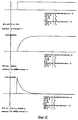
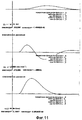
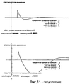
Рассмотрим отклик движения типичного пилотажного тренажера на Фиг.11 для случая ступенчатого маневра согласно входному сигналу элеронов, показанного на Фиг.6.Consider the motion response of a typical flight simulator in FIG. 11 for the case of a step maneuver according to the aileron input signal shown in FIG. 6.
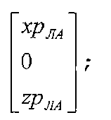
Для построения графиков были использованы фильтры второго порядка, потому что они используются чаще всего. Источником единственного входного сигнала для фильтров является угловая скорость крена. Входной сигнал в фильтр боковой удельной силы отсутствует, поскольку положением центроида вдоль оси «z» Second-order filters were used to plot the graphs, because they are used most often. The source of the only input signal for the filters is the angular roll speed. There is no input signal to the lateral specific force filter, since the position of the centroid along the z axis
(т.е. zc ЛА) в большинстве случаев пренебрегают.(i.e., zc LA ) is neglected in most cases.
Угловое ускорение крена (Фиг.11.4) демонстрирует знак, противоположный тому, который присущ угловому ускорению крена, пропущенному через фильтр нижних частот.The angular acceleration of the roll (Fig. 11.4) shows the opposite sign to that inherent in the angular acceleration of the roll passed through the low-pass filter.
Временной отклик поперечной удельной силы в базисной точке Р пилота (Фиг.11.5) демонстрирует следующие характеристики.The temporal response of the transverse specific force at the base point P of the pilot (Fig. 11.5) demonstrates the following characteristics.
1°. Начальное пиковое значение верно. Это угловое ускорение обусловлено параметром 
2°. За пиковым значением несколькими мгновениям позже следует ложная противоположная боковая удельная сила. Эта ложная сила пагубно влияет на точность воспроизведения движений пилотажным тренажером. В литературе можно найти термины «налегание, за педалями курсант, не в фазе» и т.д. (J.B.Sinacori, Northrop Corporation, "A practical approach to motion simulation", p.13, AIAA paper 73-931, сентябрь 1973 г. / Susan A. Riedel and L.G.Hofmann, Systems Technology Inc., "Investigation of nonlinear motion simulator washout schemes", p.524, p.530, Proceedings of the 14th Annual Conference on Manual Control, ноябрь 1978 / Susan A. Riedel and L.G.Hofmann, STI, "Manned engineering flight simulator validation" p.172, STI-TR-1110-1, AFFDL-TR-78-192-FT-1, февраль 1979 / David L. Quam, University of Dayton, Ohio, "Human pilot perception experiments", p.263, Proceedings of 15th Annual Conference on Manual Control, ноябрь 1979 / Irving L. Ashkenas, STI, "Collected flight and simulation comparisons and considerations", p.15-26, AGARD CP408 Flight Simulation, октябрь 1985).2 °. The peak value a few moments later is followed by a false opposite lateral specific gravity. This false power adversely affects the accuracy of motion reproduction by the flight simulator. In the literature you can find the terms "overlay, cadet pedals, out of phase", etc. (JBSinacori, Northrop Corporation, "A practical approach to motion simulation", p.13, AIAA paper 73-931, September 1973 / Susan A. Riedel and LG Hofmann, Systems Technology Inc., "Investigation of nonlinear motion simulator washout schemes ", p.524, p.530, Proceedings of the 14 th Annual Conference on Manual Control, November 1978 / Susan A. Riedel and LG Hofmann, STI," Manned engineering flight simulator validation "p.172, STI-TR-1110- 1, AFFDL-TR-78-192-FT-1, February 1979 / David L. Quam, University of Dayton, Ohio, "Human pilot perception experiments", p.263, Proceedings of 15 th Annual Conference on Manual Control, November 1979 / Irving L. Ashkenas, STI, "Collected flight and simulation comparisons and considerations", p.15-26, AGARD CP408 Flight Simulation, October 1985).
Это явление целиком обусловлено присутствием показанного на Фиг.9 фильтра, гасящего движение в направлении «y». Этот фильтр, гасящий движение в направлении «y», необходим для «возврата» тренажера и тем самым введения «его» координации.This phenomenon is entirely due to the presence of the filter shown in Fig. 9, which suppresses movement in the y direction. This filter, which suppresses movement in the y direction, is necessary to “return” the simulator and thereby introduce “its” coordination.
Единственный способ подавления этого явления в существующей схеме заключается в том, чтобы уменьшить понижающий настроечный передаточный коэффициент Kd до очень малых значений. Человек при этом не в состоянии воспринять какое-либо движение, тем более опосредованное движение, однако это считается меньшим злом, чем ложное движение.The only way to suppress this phenomenon in the existing circuit is to reduce the tuning-down gear ratio K d to very small values. At the same time, a person is not able to perceive any movement, much less an indirect movement, but this is considered a lesser evil than a false movement.
Наземный рулежный маневрGround taxiing maneuver
Во время рулежных маневров на земле, имитируемый летательный аппарат не испытывает крен, так что главную роль играют только фильтры поперечного удельного усилия.During taxiing maneuvers on the ground, the simulated aircraft does not experience a roll, so only cross-sectional force filters play the main role.
Искажение в воспринимаемом движении присутствует всегда. Когда используют руление посредством руля направления или носового колеса, начальный отклик ощущается (от «y»-фильтра верхних частот). Когда этот отклик замирает, от φ-фильтра нижних частот приходит сигнал испытываемого поперечного ускорения. Оба движения совершенно не смешиваются друг с другом, поскольку фильтры не являются комплементарными.Distortion in perceived movement is always present. When steering is used by the rudder or nose wheel, the initial response is felt (from the “y” high-pass filter). When this response freezes, a test transverse acceleration signal comes from the low-pass filter. Both movements do not mix at all, since the filters are not complementary.
Раскрытие изобретенияDisclosure of invention
Задача настоящего изобретения состоит в том, чтобы обеспечить надлежащую точность воспроизведения ощущений движения в пилотажных тренажерах, пилотажные тренажеры с такой надлежащей точностью воспроизведения ощущений движения и способы управления такими пилотажными тренажерами. Задача настоящего изобретения состоит в том, чтобы преодолеть, по меньшей мере, некоторые из недостатков, упомянутых выше.It is an object of the present invention to provide proper fidelity for the sensation of movement in flight simulators, aerobatic simulators with such proper fidelity for reproducing motion sensations and methods for controlling such aerobatic simulators. An object of the present invention is to overcome at least some of the disadvantages mentioned above.
Вышеописанные задачи решаются с помощью способа и устройства в соответствии с настоящим изобретением.The above problems are solved using the method and device in accordance with the present invention.
В первом аспекте, в изобретении предложен способ управления движениями пилотажного тренажера, приводящий к улучшенному восприятию движений пилотом, который пользуется пилотажным тренажером.In a first aspect, the invention provides a method for controlling the movements of an aerobatic simulator, resulting in improved perception of movements by a pilot who uses an aerobatic simulator.
В первом варианте осуществления первого аспекта, в настоящем изобретении предложен способ управления движениями пилотажного тренажера, предусматривающими линейные и угловые ускорения, воспринимаемые пилотом, сидящим в кресле пилота, вследствие чего угловая скорость крена и угловая скорость рыскания, а также удельная сила в поперечном направлении, вычисляемые в соответствии с моделью имитируемого летательного аппарата в фиксированной точке имитируемого летательного аппарата, преобразуются программой движения в поперечное положение и угол крена тренажера. В первом варианте осуществления, способ предусматривает вычисление угла крена тренажера в соответствии с углом крена имитируемого летательного аппарата путем коррекции первоначально вычисленного значения угла крена с коэффициентом коррекции, пропорциональным поперечной удельной силе, вносимой гасящим фильтром, используемым во время вычисления выравнивания поперечного положения тренажера в соответствии с направлением силы тяжести Земли.In the first embodiment of the first aspect, the present invention provides a method for controlling the flight simulator movements, providing linear and angular accelerations perceived by the pilot sitting in the pilot's seat, as a result of which the angular roll speed and angular yaw rate, as well as the specific force in the transverse direction, calculated in accordance with the model of the simulated aircraft at a fixed point in the simulated aircraft, are transformed by the program of movement in the transverse position and a simulator roll angle. In the first embodiment, the method comprises calculating the roll angle of the simulator in accordance with the roll angle of the simulated aircraft by correcting the initially calculated roll angle with a correction factor proportional to the transverse specific force introduced by the quenching filter used during the calculation of the alignment of the transverse position of the simulator in accordance with Earth’s direction of gravity.
Вычисление угла крена тренажера может включать в себя использование математического преобразования, предусматривающего прямую связь угла коррекции в функции преобразования угла крена в соответствии с формуламиThe calculation of the roll angle of the simulator may include the use of a mathematical transformation that provides for a direct connection of the correction angle to the roll angle conversion function in accordance with the formulas
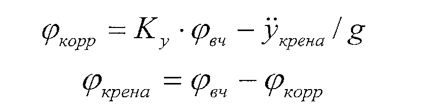
где φвч - угол крена тренажера, пропущенный через фильтр верхних частот;where φ RF is the tilt angle of the simulator, passed through a high-pass filter;

g - постоянная силы тяжести Земли;g is the constant of the Earth's gravity;
Ку - передаточный коэффициент поперечной координации;To y - gear ratio of lateral coordination;
φкрена - соответствует углу крена тренажера, получаемому в результате углового ускорения крена или угловой скорости крена летательного аппаратаφ roll - corresponds to the roll angle of the simulator, resulting from the angular acceleration of the roll or the angular roll speed of the aircraft
В упомянутом математическом преобразовании можно вводить передаточный коэффициент Ку поперечной координации в интервале между 0 и 1, что позволяет уменьшить поперечное перемещение, обуславливаемое некоторой допустимой ложной поперечной удельной силой, путем модуляции в диапазоне между «отсутствием координации» (Ку=0) и «полной координацией» (Ку=1). Угол крена может быть получен с помощью фильтра верхних частот 3-го или 4-го порядка, что приводит к получению Ку=1, а поперечное ускорение можно в каждый момент времени сделать равным этому углу крена, умноженному на ускорение силы тяжести Земли.In the aforementioned mathematical transformation, one can introduce the transfer coefficient K of the lateral coordination in the interval between 0 and 1, which allows to reduce the lateral displacement caused by some permissible false transverse specific force by modulating in the range between “lack of coordination” (K y = 0) and “ full coordination ”(K y = 1). Roll angle may be obtained using a highpass filter of the 3rd or 4th order, resulting in a K y = 1, and lateral acceleration may be at any given time is made equal to this roll angle multiplied by the acceleration of earth gravity.
Математическое преобразование может предусматривать фильтр верхних частот 2-го порядка и гасящий фильтр 1-го порядка в соответствии со следующими формулами передаточных функций:The mathematical transformation may include a high-order filter of the 2nd order and a quenching filter of the 1st order in accordance with the following transfer function formulas:

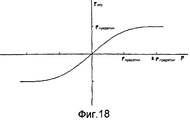
где pогр - входная угловая скорость крена, ограничиваемая посредством понижающего настроечного передаточного коэффициента Kd тренажера, а по выбору - посредством функции, ограничивающей угловую скорость крена таким образом, что для ступеньки в сигнале управления элеронами боковое перемещение тренажера имеет конечное значение.where p ogre is the input angular velocity of the roll, limited by the lower adjusting gear coefficient K d of the simulator, and, optionally, by means of the function limiting the angular velocity of the roll in such a way that the lateral movement of the simulator has a finite value for the step in the aileron control signal.
В способе, соответствующем вариантам осуществления настоящего изобретения, вторая составляющая удельной силы в поперечном направлении может быть получена посредством первого набора из двух комплементарных фильтров для углового ускорения крена и второго набора из двух комплементарных фильтров для углового ускорения рыскания. В каждом наборе комплементарных фильтров один предназначен для управления поперечным отклонением тренажера, а другой - для управления углом крена тренажера. Комплементарные фильтры могут соответствовать следующим формулам передаточных функций:In a method according to embodiments of the present invention, a second transverse specific gravity component can be obtained by a first set of two complementary filters for angular roll acceleration and a second set of two complementary filters for angular acceleration of yaw. In each set of complementary filters, one is used to control the lateral deviation of the simulator, and the other to control the roll angle of the simulator. Complementary filters can correspond to the following transfer function formulas:

иand
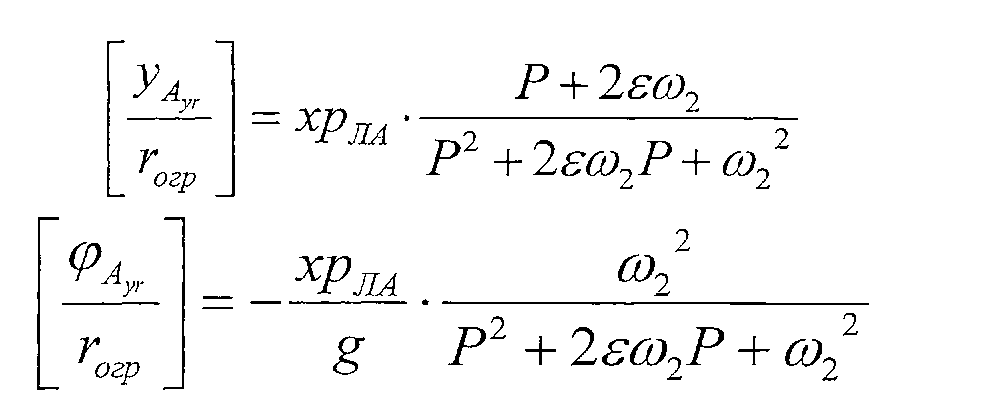
где pогр и rогр - входные угловая скорость крена и угловая скорость рыскания, соответственно, ограничиваемые посредством понижающих настроечных передаточных коэффициентов Kd и Кr, соответственно, а по выбору - посредством функции, ограничивающей угловую скорость.where p ogre and r ogre are the input angular roll speed and angular yaw rate, respectively, limited by decreasing tuning gear ratios K d and К r , respectively, and optionally by means of the function limiting the angular velocity.
Во втором варианте осуществления первого аспекта, в настоящем изобретении предложен способ управления движениями пилотажного тренажера, предусматривающими линейные и угловые ускорения, воспринимаемые пилотом, сидящим в кресле пилота, вследствие чего угловая скорость крена и угловая скорость рыскания, а также удельная сила в поперечном направлении, вычисляемые в соответствии с моделью имитируемого летательного аппарата в фиксированной точке имитируемого летательного аппарата, преобразуются программой движения в поперечное положение и угол крена тренажера. Во втором варианте осуществления, способ предусматривает:In the second embodiment of the first aspect, the present invention provides a method for controlling the flight simulator movements, providing linear and angular accelerations perceived by the pilot sitting in the pilot's seat, as a result of which the angular roll speed and angular yaw rate, as well as the specific force in the transverse direction, calculated in accordance with the model of the simulated aircraft at a fixed point in the simulated aircraft, are converted into the transverse position by the movement program e and simulator roll angle. In a second embodiment, the method comprises:
разложение удельной силы, действующей в поперечном направлении в базисной точке пилота в имитируемом летательном аппарате, на первую составляющую и вторую составляющую, причем первая составляющая связана с удельной силой в фиксированной точке имитируемого летательного аппарата, а вторая составляющая имеет первый член, связанный с ускорениями, обуславливаемыми рысканием, и второй член, связанный с угловыми ускорениями крена, в соответствии с формулой:decomposition of the specific force acting in the transverse direction at the base point of the pilot in the simulated aircraft into the first component and the second component, the first component being related to the specific force at a fixed point of the simulated aircraft, and the second component has a first term associated with accelerations caused by yaw, and the second term associated with the angular accelerations of the roll, in accordance with the formula:

где хР ЛА - координата «х» базисной точки пилота в системе координат, имеющей начало в упомянутой фиксированной точке имитируемого летательного аппарата, where x R LA - the coordinate "x" of the base point of the pilot in the coordinate system having a origin at the fixed point of the simulated aircraft,
a zP ЛА - координата «z» базисной точки пилота в упомянутой системе координат, 

фильтрацию первой составляющей Аy через два фильтра - фильтр верхних частот и фильтр нижних частот;filtering the first component And y through two filters - a high-pass filter and a low-pass filter;
параллельную фильтрацию каждого из членов второй составляющей с помощью набора из первого и второго комплементарных фильтров, причем комплементарные фильтры являются фильтрами, сумма передаточных функций которых равна единице; иparallel filtering of each of the members of the second component using a set of first and second complementary filters, and the complementary filters are filters, the sum of the transfer functions of which is equal to one; and
использование суммы выходных сигналов фильтра верхних частот и первых из комплементарных фильтров каждого набора для вычисления желаемого поперечного положения тренажера, а также использование суммы выходных сигналов фильтра нижних частот и вторых из комплементарных фильтров каждого набора для вычисления желаемого угла крена тренажера.using the sum of the output signals of the high-pass filter and the first of the complementary filters of each set to calculate the desired transverse position of the simulator, as well as the use of the sum of the output signals of the low-pass filter and the second of the complementary filters of each set to calculate the desired roll angle of the simulator.
В третьем варианте осуществления первого аспекта, в настоящем изобретении предложен способ управления движениями пилотажного тренажера, предусматривающими линейные и угловые ускорения, воспринимаемые пилотом, сидящим в кресле пилота, вследствие чего угловая скорость крена и угловая скорость рыскания, а также удельная сила в поперечном направлении, вычисляемые в соответствии с моделью имитируемого летательного аппарата в фиксированной точке имитируемого летательного аппарата, преобразуются программой движения в поперечное положение и угол крена тренажера. В третьем варианте осуществления, способ предусматривает преобразование положения базисной точки пилота в тренажере, получаемого с помощью программы движения, в положение центроида тренажера либо посредством состояния согласно известному способу, либо посредством любого из способов согласно первому или второму аспекту, либо посредством их комбинации. Это может быть сделано с помощью координационного преобразования с учетом трех углов Эйлера тренажера, т.е. угла (ψ) рыскания, угла (θ) тангажа и угла (φ) крена.In a third embodiment of the first aspect, the present invention provides a method for controlling the movements of an aerobatic simulator, providing linear and angular accelerations perceived by the pilot sitting in the pilot's seat, as a result of which the angular roll speed and angular velocity of yaw, as well as the specific force in the transverse direction, calculated in accordance with the model of the simulated aircraft at a fixed point in the simulated aircraft, are converted into the transverse position by the movement program e and simulator roll angle. In the third embodiment, the method comprises converting the position of the base point of the pilot in the simulator, obtained using the movement program, to the centroid position of the simulator, either by means of a state according to the known method, or by any of the methods according to the first or second aspect, or by a combination thereof. This can be done using coordination transformation taking into account three Euler angles of the simulator, i.e. yaw angle (ψ), pitch angle (θ) and roll angle (φ).
Способ согласно третьему варианту осуществления может дополнительно предусматривать преобразование удельной силы, вычисленной в соответствии с моделью имитируемого летательного аппарата в фиксированной точке упомянутого летательного аппарата, в удельную силу, действующую в базисной точке пилота, в качестве входного сигнала для программы движения и последующее задание этой преобразованной удельной силы в качестве входного сигнала для программы движения и преобразование выходного сигнала программы движения с помощью локального преобразования от базисной точки пилота к положению центроида тренажера в сигналы для управления положением центроида тренажера. Первое преобразование можно проводить посредством математических преобразований, преобразующих удельные силы в упомянутой фиксированной точке к базисной точке Р пилота в соответствии со следующими формулами:The method according to the third embodiment may further include converting the specific force calculated in accordance with the model of the simulated aircraft at a fixed point of said aircraft to the specific force acting at the base point of the pilot as an input signal for the movement program and then setting this converted specific forces as an input to the motion program and converting the output of the motion program using a local formation from the base point to the position of the pilot in the simulator centroid signals for controlling the position of the simulator centroid. The first transformation can be carried out by means of mathematical transformations that convert the specific forces at the fixed point to the base point P of the pilot in accordance with the following formulas:
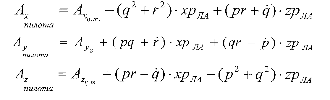
Сигналы движения для управления положением центроида платформы тренажера можно получать из положения базисной точки Р пилота, соответствующей выходному сигналу программы движения, в соответствии со следующими формулами:Motion signals for controlling the centroid position of the simulator platform can be obtained from the position of the base point P of the pilot corresponding to the output signal of the motion program, in accordance with the following formulas:
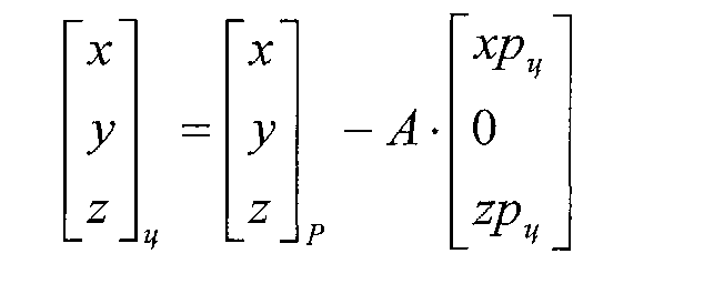
гдеWhere

Для составляющей yц центроида можно заменить вышеуказанные уравнения следующим упрощенным уравнением:For the component y c of the centroid, the above equations can be replaced by the following simplified equation:

где Δ - вертикальное расстояние между базисной точкой пилота и центроидом тренажера, а φ - угол крена.where Δ is the vertical distance between the base point of the pilot and the centroid of the simulator, and φ is the angle of heel.
Первый, второй и третий варианты осуществления первого аспекта и их зависимые признаки могут быть отдельными вариантами осуществления или могут быть объединены друг с другом.The first, second, and third embodiments of the first aspect and their dependent features may be separate embodiments or may be combined with each other.
В вариантах осуществления настоящего изобретения, фиксированной точкой имитируемого летательного аппарата может быть центр тяжести упомянутого имитируемого летательного аппарата. Альтернативными точками, используемыми в качестве упомянутой фиксированной точки, могут быть другие фиксированные точки в летательном аппарате по соседству с центром тяжести.In embodiments of the present invention, the fixed point of the simulated aircraft may be the center of gravity of the simulated aircraft. Alternative points used as said fixed point may be other fixed points in the aircraft adjacent to the center of gravity.
Во втором аспекте, в изобретении предложен компьютерный программный продукт для осуществления способов, заявляемых в любом из предшествующих пунктов формулы изобретения, при осуществлении этого способа на компьютерном устройстве, связанном с пилотажным тренажером, имитирующим летательный аппарат. Этот компьютерный программный продукт обеспечивает функциональные возможности согласно любому из вышеописанных способов в соответствии с настоящим изобретением при его осуществлении на компьютерном устройстве, связанном с пилотажным тренажером. Компьютерная программа может быть частью продукта программного обеспечения компьютера (например, может находиться на программоносителе), который включает в себя один или более кодовых сегментов, обуславливающих выполнение этапов способа процессором, таким как центральный процессор обрабатывающей системы. Программа работает под управлением операционной системы и может включать в себя пользовательский интерфейс, который гарантирует пользователю взаимодействие с программой. Программа пилотажного тренажера работает с входными данными, например с заранее заданной схемой полета, и генерирует данные управления, предназначенные для управления движениями платформы пилотажного тренажера.In a second aspect, the invention provides a computer program product for implementing the methods claimed in any of the preceding claims when implementing this method on a computer device associated with a flight simulator simulating an aircraft. This computer program product provides functionality according to any of the above methods in accordance with the present invention when it is implemented on a computer device associated with a flight simulator. A computer program may be part of a computer software product (for example, may reside on a program carrier), which includes one or more code segments that determine the steps of the method by a processor, such as a central processing unit processor. The program runs under the operating system and may include a user interface that guarantees the user interaction with the program. The flight simulator program works with input data, for example, with a predetermined flight pattern, and generates control data designed to control the movements of the flight simulator platform.
В третьем аспекте, в настоящем изобретении предложено считываемое компьютером устройство для хранения данных или программоноситель, которое или который хранит компьютерный программный продукт согласно настоящему изобретению в машиночитаемой форме и которое или который осуществляет, по меньшей мере, один из способов согласно изобретению, когда он осуществляется на компьютерном устройстве. В настоящее время такое программное обеспечение часто предлагается по сети Internet или внутрикорпоративной сети на базе технологии Internet для загрузки, поэтому настоящее изобретение предусматривает передачу компьютерного программного продукта в соответствии с настоящим изобретением через локальную или глобальную вычислительную сеть. Вычислительное устройство может включать в себя либо микропроцессор, либо FPGA - вентильную матрицу, программируемую во время эксплуатации.In a third aspect, the present invention provides a computer-readable device for storing data or a storage medium that or which stores a computer program product according to the present invention in machine-readable form and which or which implements at least one of the methods according to the invention when it is carried out on computer device. Currently, such software is often offered over the Internet or an intranet based on Internet technology for download, therefore, the present invention provides for the transfer of a computer program product in accordance with the present invention through a local or global computer network. A computing device can include either a microprocessor or an FPGA gate array programmed during operation.
В том смысле, в каком они употребляются в данном описании, термины «программоноситель» и «машиночитаемый носитель информации» относятся к любому носителю информации, который принимает участие в выдаче команд в процессор для исполнения. Такой носитель информации может принимать многие формы, включая, но не в ограничительном смысле, энергонезависимые носители информации, энергозависимые носители информации и среды передачи информации. Энергонезависимые носители информации включают в себя динамическое запоминающее устройство, такое как оперативное запоминающее устройство (ОЗУ). Среды передачи включают в себя коаксиальные кабели, медный провод и волоконную оптику, в том числе провода, которые представляют собой шину внутри компьютера. Среды передачи также могут принимать форму акустических или световых волн, таких как генерируемые во время обмена данными в диапазоне радиоволн и инфракрасных волн.In the sense in which they are used in this description, the terms "program carrier" and "computer-readable storage medium" refer to any storage medium that is involved in issuing instructions to the processor for execution. Such a storage medium can take many forms, including, but not limited to, non-volatile storage media, volatile storage media and transmission media. Non-volatile storage media include dynamic storage device, such as random access memory (RAM). Transmission media include coaxial cables, copper wire, and fiber optics, including wires that are the bus inside the computer. Transmission media can also take the form of acoustic or light waves, such as those generated during data exchange in the range of radio waves and infrared waves.
Распространенные формы считываемых компьютером носителем включают в себя, например, флоппи-диск, гибкий диск, жесткий диск, магнитную ленту или любой другой магнитный носитель информации, CD-ROM, любой другой оптический носитель информации, перфокарты, бумажные ленты, любой другой материальный носитель информации с рисунками отверстий, ОЗУ, программируемое постоянное запоминающее устройство (ППЗУ), стираемое программируемое постоянное запоминающее устройство (СППЗУ), СППЗУ типа флэш-памяти, любую другую запоминающую микросхему или картридж, несущую волну, как описано выше, или любой другой носитель информации, с которого возможно считывание компьютером.Common forms of computer-readable media include, for example, a floppy disk, floppy disk, hard disk, magnetic tape or any other magnetic storage medium, CD-ROM, any other optical storage medium, punched cards, paper tapes, any other material storage medium with hole patterns, RAM, programmable read-only memory (EPROM), erasable programmable read-only memory (EPROM), EPROM type flash memory, any other memory chip or card j, a carrier wave, as described above, or any other storage medium from which it can be read by a computer.
При переносе одной или нескольких последовательностей одной или нескольких команд в процессор для исполнения можно задействовать считываемые компьютером носители, представленные в разных формах. Например, команды могут быть изначально размещены на магнитном диске удаленного компьютера. Удаленный компьютер может загружать команды в свое динамическое запоминающее устройство и посылать эти команды по телефонной линии, пользуясь модемом. Модем, локальный по отношению к компьютерной системе для управления платформой тренажера, может принимать данные по этой телефонной линии и использовать передатчик инфракрасного излучения для преобразования данных в сигнал инфракрасного излучения. Детектор инфракрасного излучения, подключенный к шине, может принимать данные, переносимые в сигнале инфракрасного излучения, и размещать эти данные на шине. Шина переносит данные в основное запоминающее устройство, из которого процессор выбирает команды и выполняет их. Команды, принимаемые основным запоминающим устройством, можно, по выбору, сохранять в некотором запоминающем устройстве либо перед их выполнением процессором, либо после такого выполнения. Команды можно также передавать посредством несущей волны в сети, такой как локальная вычислительная сеть (ЛВС), глобальная вычислительная сеть (ГВС) или объединенная сеть. Среды передачи могут принимать форму акустических или световых волн, таких как генерируемые во время обмена данными в диапазоне радиоволн и инфракрасных волн. Среды передачи включают в себя коаксиальные кабели, медный провод и волоконную оптику, в том числе провода, которые образуют шину внутри компьютера.When you transfer one or more sequences of one or more instructions to the processor, you can use computer-readable media in various forms to execute. For example, commands can be initially placed on the magnetic disk of a remote computer. A remote computer can download commands to its dynamic storage device and send these commands over a telephone line using a modem. A modem local to the computer system for controlling the simulator platform can receive data on this telephone line and use an infrared transmitter to convert the data into an infrared signal. An infrared detector connected to the bus can receive data carried in the infrared signal and place this data on the bus. The bus transfers data to the main storage device from which the processor selects instructions and executes them. The commands received by the main storage device can, optionally, be stored in some storage device either before they are executed by the processor, or after such execution. Commands can also be transmitted via a carrier wave in a network, such as a local area network (LAN), wide area network (WAN), or interconnected network. Transmission media can take the form of acoustic or light waves, such as those generated during data exchange in the range of radio waves and infrared waves. Transmission media include coaxial cables, copper wire, and fiber optics, including wires that form the bus inside the computer.
В еще одном аспекте, в настоящем изобретении предложен контроллер для управления движениями пилотажного тренажера, предусматривающими линейные и угловые ускорения, воспринимаемые пилотом, сидящим в кресле пилота, вследствие чего угловая скорость крена и угловая скорость рыскания, а также удельная сила в поперечном направлении, вычисляемые в соответствии с моделью имитируемого летательного аппарата в фиксированной точке имитируемого летательного аппарата, преобразуются программой движения в поперечное положение и угол крена тренажера,In yet another aspect, the present invention provides a controller for controlling the flight simulator, providing linear and angular accelerations perceived by the pilot sitting in the pilot’s seat, as a result of which the angular roll speed and angular yaw rate, as well as the transverse specific force calculated in in accordance with the model of the simulated aircraft at a fixed point in the simulated aircraft, are converted by the movement program into the transverse position and the roll angle ra
при этом контроллер содержит любые компоненты из таких, как:the controller contains any components from such as:
первый вычислительный блок, выполненный с возможностью вычисления угла крена тренажера, обуславливаемого углом крена имитируемого летательного аппарата, путем коррекции первоначально вычисленного значения угла крена с коэффициентом коррекции, пропорциональным поперечной удельной силе, вносимой гасящим фильтром, используемым во время вычисления выравнивания поперечного положения тренажера в соответствии с направлением силы тяжести Земли,the first computing unit, configured to calculate the roll angle of the simulator, caused by the roll angle of the simulated aircraft, by correcting the initially calculated roll angle with a correction factor proportional to the transverse specific force introduced by the quenching filter used during the calculation of alignment of the transverse position of the simulator in accordance with Earth’s direction of gravity
и/или.and / or.
второй вычислительный блок, выполненный с возможностью разложения удельной силы, действующей в поперечном направлении в базисной точке пилота в имитируемом летательном аппарате, на первую составляющую и вторую составляющую, причем первая составляющая связана с удельной силой в фиксированной точке имитируемого летательного аппарата, а вторая составляющая имеет первый член, связанный с ускорениями, обуславливаемыми рысканием, и второй член, связанный с угловыми ускорениями крена, в соответствии с формулой:a second computing unit configured to decompose the specific force acting in the transverse direction at the base point of the pilot in the simulated aircraft into a first component and a second component, the first component being related to the specific force at a fixed point of the simulated aircraft, and the second component has a first a term associated with yaw accelerations and a second term associated with angular roll accelerations in accordance with the formula:

где хР ЛА - координата «х» базисной точки пилота в системе координат, имеющей начало в упомянутой фиксированной точке имитируемого летательного аппарата, where x R LA - the coordinate "x" of the base point of the pilot in the coordinate system having a origin at the fixed point of the simulated aircraft,
a zP ЛА - координата «z» базисной точки пилота в упомянутой системе координат, 

фильтр верхних частот и фильтр нижних частот для фильтрации первой составляющей Аy;a high-pass filter and a low-pass filter for filtering the first component A y ;
два набора, каждый из которых состоит из первого и второго комплементарных фильтров, причем комплементарные фильтры являются фильтрами, сумма передаточных функций которых равна единице, для параллельной фильтрации каждого из членов второй составляющей; иtwo sets, each of which consists of the first and second complementary filters, and complementary filters are filters, the sum of the transfer functions of which is equal to one, for parallel filtering of each of the members of the second component; and
сумматор для суммирования выходного сигнала фильтра верхних частот и выходных сигналов первых из комплементарных фильтров каждого набора для вычисления желаемого поперечного положения тренажера, а также сумматор для суммирования выходного сигнала фильтра нижних частот и выходных сигналов вторых из комплементарных фильтров каждого набора для вычисления желаемого угла крена тренажера,an adder for summing the output signal of the high-pass filter and the output signals of the first of the complementary filters of each set to calculate the desired transverse position of the simulator, as well as an adder for summing the output signal of the low-pass filter and the output signals of the second of the complementary filters of each set to calculate the desired roll angle of the simulator,
и/илиand / or
блок преобразования, предназначенный для преобразования положения базисной точки пилота в тренажере, получаемого с помощью программы движения, в положение центроида тренажера либо посредством состояния согласно известному способу, либо посредством любого из способов согласно первому или второму аспекту, либо посредством их комбинации.a conversion unit for converting the position of the base point of the pilot in the simulator, obtained using the movement program, into the centroid position of the simulator, either by means of a state according to a known method, or by any of the methods according to the first or second aspect, or by a combination thereof.
В еще одном аспекте, в настоящем изобретении предложен пилотажный тренажер, выполненный с возможностью совершения управляемых движений, предусматривающих линейные и угловые ускорения, воспринимаемые пилотом, сидящим в кресле пилота, вследствие чего угловая скорость крена и угловая скорость рыскания, а также удельная сила в поперечном направлении, вычисляемые в соответствии с моделью имитируемого летательного аппарата в фиксированной точке имитируемого летательного аппарата, преобразуются программой движения в поперечное положение и угол крена тренажера,In yet another aspect, the present invention provides an aerobatic simulator configured to perform controlled movements involving linear and angular accelerations perceived by a pilot sitting in a pilot's seat, resulting in angular roll speed and angular yaw rate, as well as specific force in the transverse direction calculated in accordance with the model of the simulated aircraft at a fixed point in the simulated aircraft are converted by the movement program into the transverse position and the roll angle of the simulator,
при этом пилотажный тренажер содержит любые компоненты из таких, как:while the flight simulator contains any components from such as:
первый вычислительный блок, выполненный с возможностью вычисления угла крена тренажера, обуславливаемого углом крена имитируемого летательного аппарата, путем коррекции первоначально вычисленного значения угла крена с коэффициентом коррекции, пропорциональным поперечной удельной силе, вносимой гасящим фильтром, используемым во время вычисления выравнивания поперечного положения тренажера в соответствии с направлением силы тяжести Земли,the first computing unit, configured to calculate the roll angle of the simulator, caused by the roll angle of the simulated aircraft, by correcting the initially calculated roll angle with a correction factor proportional to the transverse specific force introduced by the quenching filter used during the calculation of alignment of the transverse position of the simulator in accordance with Earth’s direction of gravity
и/илиand / or
второй вычислительный блок, выполненный с возможностью разложения удельной силы, действующей в поперечном направлении в базисной точке пилота в имитируемом летательном аппарате, на первую составляющую и вторую составляющую, причем первая составляющая связана с удельной силой в фиксированной точке имитируемого летательного аппарата, а вторая составляющая имеет первый член, связанный с ускорениями, обуславливаемыми рысканием, и второй член, связанный с угловыми ускорениями крена, в соответствии с формулой:a second computing unit configured to decompose the specific force acting in the transverse direction at the base point of the pilot in the simulated aircraft into a first component and a second component, the first component being related to the specific force at a fixed point of the simulated aircraft, and the second component has a first a term associated with yaw accelerations and a second term associated with angular roll accelerations in accordance with the formula:

где хР ЛА - координата «х» базисной точки пилота в системе координат, имеющей начало в упомянутой фиксированной точке имитируемого летательного аппарата, where x R LA - the coordinate "x" of the base point of the pilot in the coordinate system having a origin at the fixed point of the simulated aircraft,
a zP ЛА - координата «z» базисной точки пилота в упомянутой системе координат, 

фильтр верхних частот и фильтр нижних частот для фильтрации первой составляющей Аy;a high-pass filter and a low-pass filter for filtering the first component A y ;
два набора, каждый из которых состоит из первого и второго комплементарных фильтров, причем комплементарные фильтры являются фильтрами, сумма передаточных функций которых равна единице, для параллельной фильтрации каждого из членов второй составляющей; иtwo sets, each of which consists of the first and second complementary filters, and complementary filters are filters, the sum of the transfer functions of which is equal to one, for parallel filtering of each of the members of the second component; and
сумматор для суммирования выходного сигнала фильтра верхних частот и выходных сигналов первых из комплементарных фильтров каждого набора для вычисления желаемого поперечного положения тренажера, а также сумматор для суммирования выходного сигнала фильтра нижних частот и выходных сигналов вторых из комплементарных фильтров каждого набора для вычисления желаемого угла крена тренажера,an adder for summing the output signal of the high-pass filter and the output signals of the first of the complementary filters of each set to calculate the desired transverse position of the simulator, as well as an adder for summing the output signal of the low-pass filter and the output signals of the second of the complementary filters of each set to calculate the desired roll angle of the simulator,
и/илиand / or
блок преобразования, предназначенный для преобразования положения базисной точки пилота в тренажере, получаемого с помощью программы движения, в положение центроида тренажера либо посредством состояния согласно известному способу, либо посредством любого из способов согласно первому или второму аспекту, либо посредством их комбинации.a conversion unit for converting the position of the base point of the pilot in the simulator, obtained using the movement program, into the centroid position of the simulator, either by means of a state according to a known method, or by any of the methods according to the first or second aspect, or by a combination thereof.
Конкретные и предпочтительные аспекты изобретения приведены в прилагаемых независимых и зависимых пунктах формулы изобретения. Признаки из зависимых пунктов формулы изобретения могут быть объединены с признаками независимых пунктов формулы изобретения и с признаками других зависимых пунктов формулы изобретения подходящим образом, а не только так, как буквально изложено в формуле изобретения.Specific and preferred aspects of the invention are set forth in the attached independent and dependent claims. The features of the dependent claims may be combined with the features of the independent claims and with the features of the other dependent claims in a suitable manner, and not only as literally set forth in the claims.
Предполагается, что эти концепции представляют собой существенно новые, неизвестные ранее усовершенствования, предусматривающие выход за рамки общепринятых практических методик, а это приводит к повышенной точности воспроизведения ощущений движения во время маневров в поперечном направлении на земле и в воздухе.It is assumed that these concepts are essentially new, previously unknown improvements that provide for going beyond the scope of generally accepted practical methods, and this leads to increased accuracy in reproducing the sensations of movement during maneuvers in the transverse direction on the ground and in the air.
Положения настоящего изобретения позволяют проектировать пилотажные тренажеры и способы управления пилотажными тренажерами.The provisions of the present invention allow the design of flight simulators and methods for controlling flight simulators.
Вышеуказанные и другие характеристики, признаки и преимущества настоящего изобретения станут очевидными из нижеследующего подробного описания, приводимого в связи с прилагаемыми чертежами, которые иллюстрируют на примерах принципы изобретения. Это описание приводится лишь в качестве примера, ни в коей мере не ограничивающего объем притязаний изобретения. Позиции, цитируемые ниже, относятся к прилагаемым чертежам.The above and other characteristics, features and advantages of the present invention will become apparent from the following detailed description given in connection with the accompanying drawings, which illustrate by way of example the principles of the invention. This description is given only as an example, in no way limiting the scope of the claims of the invention. The items cited below refer to the accompanying drawings.
Краткое описание чертежейBrief Description of the Drawings
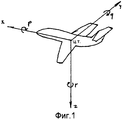
Фиг.1: Система координат летательного аппарата.Figure 1: Aircraft coordinate system.
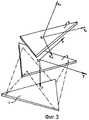
Фиг.2: Фиксированная платформа системы координат тренажера:Figure 2: Fixed platform coordinate system simulator:
1: центроид тренажера;1: centroid simulator;
2: верхняя подвижная платформа;2: upper movable platform;
3: нижняя подвижная платформа.3: lower movable platform.
Фиг.3: Система координат подвижных платформ:Figure 3: Coordinate system of moving platforms:
1: исходное положение центроида;1: initial position of the centroid;
2: движущийся центроид;2: moving centroid;
3: верхняя подвижная платформа в покое;3: upper movable platform at rest;
4: верхняя подвижная платформа в движении;4: upper movable platform in motion;
5: нижняя подвижная платформа.5: lower movable platform.
Фиг.4: Базисная точка пилота - центроид платформы центр тяжести (ц.т.) летательного аппарата:Figure 4: The base point of the pilot is the centroid of the platform center of gravity (ts) of the aircraft:
1: летательный аппарат;1: aircraft;
2: тренажер в гипотетическом месте;2: simulator in a hypothetical place;
Р: базисная точка пилота;P: base point of the pilot;
ц: центроид;q: centroid;
ц.т.: центр тяжести;DH: center of gravity;
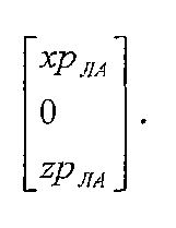
координаты базисной точки пилота относительно ц.т. летательного аппарата:the coordinates of the base point of the pilot relative to t.t. aircraft:
координаты базисной точки пилота относительно ц.т. летательного аппарата:the coordinates of the base point of the pilot relative to t.t. aircraft:
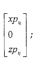
координаты центроида относительно ц.т. летательного аппарата:coordinates of the centroid relative to c.t. aircraft:
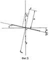
Фиг.5: Удельная сила в направлении «у» в точке Р подвижной платформы:Figure 5: Specific force in the direction of "y" at point P of the moving platform:
1: подвижная платформа.1: movable platform.
Фиг.6: Изменение положений платформы во времени для ступеньки в элероне:6: Changing the position of the platform in time for the steps in the aileron:
6.1: входной сигнал элерона (°);6.1: aileron input signal (°);
6.2: угловая скорость крена (°/сек);6.2: angular roll speed (° / sec);
6.3: угловое ускорение крена (°/сек2).6.3: angular roll acceleration (° / sec 2 ).
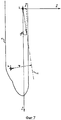
Фиг.7: Мгновенная ось крена, обуславливаемая входным сигналом элеронов:Fig. 7: Instantaneous roll axis, caused by the input of the ailerons:
1: летательный аппарат;1: aircraft;
2: мгновенная ось крена.2: instantaneous roll axis.
Фиг.8: Блок-схема «классических преобразований».Fig: Block diagram of the "classic transformations".
Фиг.9: Классические фильтры, канал крена.Fig.9: Classic filters, roll channel.
Фиг.10: Классические фильтры, канал поперечных удельных сил.Figure 10: Classical filters, channel transverse specific forces.
Фиг.11: Классические фильтры изменений положений пилотажного тренажера во времени:11: Classic filters changes in the position of the flight simulator over time:
11.1: поперечное положение (м) центроида;11.1: lateral position (m) of the centroid;
11.2: поперечное ускорение (м/сек2) центроида;11.2: lateral acceleration (m / s 2 ) of the centroid;
11.3: угол крена (°);11.3: roll angle (°);
11.4: угловое ускорение крена (°/сек2);11.4: angular roll acceleration (° / sec 2 );
11.5: удельная сила Аy Р (м/сек2).11.5: specific gravity A y P (m / s 2 ).
Фиг.12: Блок-схема «корректируемых» преобразований в соответствии с вариантом осуществления настоящего изобретения.12: A block diagram of “adjustable” transformations in accordance with an embodiment of the present invention.
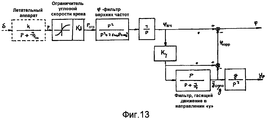
Фиг.13: Канал крена с введением φкорр в соответствии с вариантом осуществления настоящего изобретения.Fig: Roll channel with the introduction of φ corr in accordance with an embodiment of the present invention.
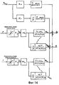
Фиг.14: Канал боковой удельной силы с разложением Аy и комплементарными фильтрами в соответствии с вариантом осуществления настоящего изобретения:Fig: Channel lateral specific gravity with decomposition And y and complementary filters in accordance with an embodiment of the present invention:
1: комплементарные фильтры: Аy пилота, обусловленная угловым ускорением крена;1: complementary filters: A y of the pilot due to angular roll acceleration;
2: комплементарные фильтры: Аy пилота, обусловленная угловым ускорением рыскания.2: complementary filters: A y of the pilot due to angular acceleration of yaw.
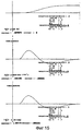
Фиг.15: Изменения положений пилотажного тренажера во времени с использованием «опережающей подачи» φкорр в соответствии с вариантом осуществления настоящего изобретения:Fig: Changes in the position of the flight simulator in time using the "leading feed" φ corr in accordance with an embodiment of the present invention:
15.1: поперечное положение (м) точки Р;15.1: transverse position (m) of point P;
15.2: поперечное ускорение (м/сек2) точки Р;15.2: lateral acceleration (m / s 2 ) of point P;
15.3: угол крена (°);15.3: roll angle (°);
15.4: угловое ускорение крена (°/сек2);15.4: angular roll acceleration (° / sec 2 );
15.5: удельная сила Аy Р (м/сек2).15.5: specific force A y P (m / s 2 ).
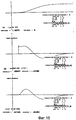
Фиг.16: Изменения положений пилотажного тренажера полностью согласно новой концепции для Кy=1 в соответствии с вариантом осуществления настоящего изобретения:Fig: Changes in the position of the flight simulator completely in accordance with the new concept for K y = 1 in accordance with an embodiment of the present invention:
16.1: поперечное положение (м) точки Р;16.1: lateral position (m) of point P;
16.2: поперечное ускорение (м/сек2) точки Р;16.2: lateral acceleration (m / s 2 ) of point P;
16.3: угол крена (°);16.3: roll angle (°);
16.4: угловое ускорение крена (°/сек2);16.4: angular acceleration of the roll (° / sec 2 );
16.5: удельная сила Аy Р (м/сек2).16.5: specific force A y P (m / s 2 ).
Фиг.17: Изменения положений пилотажного тренажера полностью согласно новой концепции для Ку=0,8 в соответствии с вариантом осуществления настоящего изобретения:Fig: Changes in the position of the flight simulator completely in accordance with the new concept for K y = 0.8 in accordance with an embodiment of the present invention:
17.1: поперечное положение (м) точки Р;17.1: lateral position (m) of point P;
17.2: поперечное ускорение (м/сек2) точки Р;17.2: lateral acceleration (m / s 2 ) of point P;
17.3: угол крена (°);17.3: roll angle (°);
17.4: угловое ускорение крена (°/сек2);17.4: angular acceleration of the roll (° / sec 2 );
17.5: удельная сила Аy Р (м/сек2).17.5: specific force A y P (m / s 2 ).
Фиг.18: Пример функции, ограничивающей угловую скорость крена, в соответствии с вариантом осуществления настоящего изобретения.Fig. 18: An example of a function limiting the angular velocity of a roll according to an embodiment of the present invention.
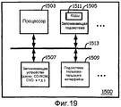
Фиг.19: Изображение компьютерной системы для использования с настоящим изобретением.Fig: Image of a computer system for use with the present invention.
Фиг.20: Изображение пилотажного тренажера.Fig: Image of a flight simulator.
Осуществление изобретенияThe implementation of the invention
Настоящее изобретение будет описано применительно к конкретным вариантам осуществления и со ссылками на прилагаемые чертежи, но изобретение ограничивается не этим, а только прилагаемой формулой изобретения. Описываемые чертежи являются условными и не носят ограничительный характер. В иллюстративных целях размеры некоторых элементов на чертежах могут быть преднамеренно увеличены и представлены не в масштабе. Эти размеры и относительные размеры не соответствуют реальным уменьшенным копиям вариантов практической реализации изобретения.The present invention will be described with reference to specific embodiments and with reference to the accompanying drawings, but the invention is not limited thereto, but only by the appended claims. The described drawings are conditional and are not restrictive. For illustrative purposes, the dimensions of some elements in the drawings may be deliberately enlarged and not to scale. These sizes and relative sizes do not correspond to real reduced copies of the variants of the practical implementation of the invention.
Кроме того, термины «первый», «второй», «третий» и т.п. употребляются в описании и формуле изобретения для установления различий между аналогичными элементами и не являются обязательными для описания последовательного илиIn addition, the terms “first”, “second”, “third”, etc. are used in the description and claims to distinguish between similar elements and are not required to describe a sequential or
хронологического порядка. Следует понять, что употребляемые таким образом термины являются взаимозаменяемыми в подходящих обстоятельствах и что описываемые здесь варианты осуществления изобретения могут работать в последовательностях, отличающихся от описываемых здесь.chronological order. It should be understood that the terms used in this way are used interchangeably in suitable circumstances and that the embodiments described herein may work in sequences different from those described here.
Необходимо отметить, что не следует интерпретировать термин «содержащий» («содержащее»), употребляемый в формуле изобретения, как ограничивающий перечисляемые после него средства; он не исключает другие элементы или этапы. Таким образом, его следует интерпретировать как указывающий наличие излагаемых признаков, цельных узлов, этапов или компонентов, к которым он относится, а не исключающий наличие или добавление одного или нескольких других признаков, цельных узлов, этапов или компонентов либо их групп. Таким образом, объем выражения «устройство, содержащее средства А и В» не следует ограничивать устройствами, состоящими только из компонентов А и В. Это выражение в контексте настоящего изобретения означает, что единственными релевантными компонентами упомянутого устройства являются А и В.It should be noted that the term “comprising” (“comprising”) used in the claims should not be interpreted as limiting the funds listed after it; it does not exclude other elements or steps. Thus, it should be interpreted as indicating the presence of the stated features, integral units, steps or components to which it relates, and not excluding the presence or addition of one or more other features, integral units, stages or components or their groups. Thus, the scope of the expression “device containing means A and B” should not be limited to devices consisting only of components A and B. This expression in the context of the present invention means that the only relevant components of said device are A and B.
Определения и аннотацииDefinitions and annotations
Нижеследующие термины представлены просто для того, чтобы способствовать пониманию изобретения. Эти определения не следует считать имеющими объем меньший, чем тот, который понятен обычному специалисту в данной области техники.The following terms are presented merely to facilitate an understanding of the invention. These definitions should not be considered to have a volume less than that which is understood by an ordinary person skilled in the art.
ЛА летательный аппаратAircraft
А матрица направляющих косинусовAnd the matrix of guide cosines
Аx составляющая удельной силы вдоль оси «х»And x is the component of the specific force along the x-axis
Аy составляющая удельной силы вдоль оси «у»And y is the component of the specific force along the y axis
Az составляющая удельной силы вдоль оси «z»A z component of the specific gravity along the axis "z"
Ау центроида Ау в гипотетическом месте нахождения центроида по отношению к системе координат ЛАAnd the centroid A y in a hypothetical location of the centroid with respect to the coordinate system of the aircraft
Ау ц.т. Ау в ц.т. ЛАAnd at c. And in cg LA
Ау пилота Ау пилота по отношению к системе координат ЛАAnd the pilot And the pilot in relation to the coordinate system of the aircraft
Ау Р Ау в базисной точке Р пилота в тренажереAnd at P A at the base point P of the pilot in the simulator
Ц центроид - геометрический центр тяжести движущейся платформыTs centroid - the geometric center of gravity of a moving platform
ц.т. центр тяжестиc.t. center of gravity
d расстояние между Р и осью углового ускорения кренаd the distance between P and the axis of the angular acceleration of the roll
g ускорение силы тяжести Земли - 9,81 м/сек2 g acceleration of gravity of the Earth - 9.81 m / s 2
k передаточное отношениеk gear ratio
Kd понижающий настроечный передаточный коэффициент в канале кренаK d reduction tuning gear in the roll channel
Кр понижающий настроечный передаточный коэффициент в канале Ау, входной сигнал кренаK p reducing tuning gear in channel A y , the input roll signal
Кr понижающий настроечный передаточный коэффициент в канале Ау, входной сигнал рысканияK r lower tuning gear in channel A y , the input yaw signal
Квч понижающий настроечный передаточный коэффициент классического «у»-фильтра верхних частотBy lowering HF tuning gain classic "y" -filter highpass
Кнч понижающее настроечное передаточное отношение классического «у»-фильтра нижних частотTo low-frequency lower tuning gear ratio of the classic “y” low-pass filter
Ку передаточный коэффициент поперечной координацииK u gear ratio of lateral coordination
Р угловая скорость кренаP roll angular velocity
Р оператор Лапласа (означает: d/dt); базисная точка пилотаP is the Laplace operator (means: d / dt); base point of the pilot
рпред предел угловой скорости кренаp pre limit of angular roll velocity
рогр ограниченная угловая скорость кренаp ogre limited angular roll speed
q угловая скорость тангажаq pitch angular velocity
r угловая скорость рысканияr yaw rate
rпред предел угловой скорости рысканияr prev limit yaw rate
rогр ограниченная угловая скорость рысканияr ogre limited yaw rate
хс ЛА координата «х» центроида в системе отсчета ЛАxs LA coordinate "x" of the centroid in the aircraft reference frame
zc ЛА координата «z» центроида в системе отсчета ЛАzc LA coordinate “z” of the centroid in the aircraft reference frame
хР ЛА координата «х» точки Р в системе отсчета ЛАx P LA coordinate "x" of point P in the reference frame of the aircraft
zP ЛА координата «z» точки Р в системе отсчета ЛАz P LA coordinate “z” of point P in the aircraft reference frame
хР ц координата «х» точки Р в системе подвижной платформыx R c the coordinate "x" of the point P in the system of the moving platform
zP ц координата «z» точки Р в системе подвижной платформыz P c the coordinate "z" of the point P in the system of the moving platform
у координата «у»y coordinate "y"
у-ц координата «у» центроида в системе отсчета фиксированной платформыy - coordinate of the "y" centroid in the reference system of a fixed platform
у-р координата «у» точки Р в системе отсчета фиксированной платформыy- p coordinate "y" of point P in the reference system of a fixed platform
δ отклонение (градусы) штурвала управленияδ deviation (degrees) of the control wheel
ψ угол рысканияψ yaw angle
θ угол тангажаθ pitch angle
φ угол кренаφ roll angle
φвч фильтр верхних частот угла кренаφ HF roll angle high pass filter frequency
φкорр новая концепция коррекции угла кренаφ corr new roll angle correction concept
Δ вертикальное расстояние между базисной точкой Р пилота и центроидом «ц» платформыΔ is the vertical distance between the base point P of the pilot and the centroid “ts” of the platform
τ постоянная времени (сек)τ time constant (sec)
ω круговая частота (рад/сек)ω circular frequency (rad / s)
ξ декремент затуханияξ decrement of attenuation
сn коэффициент момента рысканияwith n yaw moment coefficient
ci коэффициент момента кренаc i roll moment coefficient
cnδ=∂cn/∂δc nδ = ∂c n / ∂δ
сiδ=∂сi/∂δwith iδ = ∂с i / ∂δ


Системы отсчетаReference systems
Все системы отсчета являются правыми, и в них ось «х» обращена вверх, ось «у» - вправо, а ось «z» - вниз.All reference systems are right, and in them the x axis is turned up, the y axis is to the right, and the z axis is down.
На Фиг.1 изображена система отсчета летательного аппарата, имеющая начало в фиксированной точке, например в центре тяжести. На Фиг.2 изображена система отсчета фиксированной платформы, имеющая начало в исходном положении центроида. На Фиг.3 показана система координат подвижной платформы, имеющая начало в центроиде.Figure 1 shows the reference system of the aircraft, having a beginning at a fixed point, for example at the center of gravity. Figure 2 shows the reference system of a fixed platform having a beginning in the initial position of the centroid. Figure 3 shows the coordinate system of a moving platform having a origin in a centroid.
Базисная точка Р пилота (Фиг.4)The base point P of the pilot (Figure 4)
Точка, где, согласно допущению, происходит восприятие движения. Движение воспринимается через посредство полукруглых каналов внутреннего уха. Вместе с тем, имеет место также тактильное восприятие движения (также называемое «центром пульсаций»). Поэтому предполагается, что точка Р находится между 2-мя пилотами на половине высоты между их головой и подушкой кресла. В типичном пилотажном тренажере расстояние Δ между базисной точкой Р пилота и центроидом «ц» тренажера составляет от 1,00 до 1,75 м.The point where, according to the assumption, the perception of movement occurs. The movement is perceived through the semicircular canals of the inner ear. At the same time, there is also a tactile perception of movement (also called the "center of pulsations"). Therefore, it is assumed that point P is between 2 pilots at half height between their head and the seat cushion. In a typical flight simulator, the distance Δ between the base point P of the pilot and the centroid “t” of the simulator is from 1.00 to 1.75 m.
Удельная сила (м/сек2)Specific Strength (m / s 2 )
Удельная сила в заданном направлении равна линейному ускорению, которое можно было бы измерить линейным акселерометром в этом направлении. Она равна векторной разности между кинематическим ускорением и ускорением, обусловленным силой тяжести. Удельная сила (Аy Р) в заданной точке Р на подвижной платформе состоит из 3-х составляющих: ускорения центроида (

Модель летательного аппарата в полетеModel of the aircraft in flight
В соответствии с первоисточником Н.Wittenberg, Technische Hogeschool Delft, "Elementaire beschouwing over de samenhang tussen besturing, stabiliteit en demping bij vliegtuigen", Memorandum M-319, октябрь 1979, с.5-7), используется приближение первого порядка со следующей передаточной функцией:According to the original source of H. Wittenberg, Technische Hogeschool Delft, "Elementaire beschouwing over de samenhang tussen besturing, stabiliteit en demping bij vliegtuigen", Memorandum M-319, October 1979, pp. 5-7), the first-order approximation with the next transfer function:
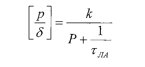
Это хорошее приближение для ситуации координированных разворотов (удельная сила вдоль оси «у» в ц.т. летательного аппарата отсутствует).This is a good approximation for a situation of coordinated turns (there is no specific force along the "y" axis in the centerpiece of the aircraft).
На Фиг.6 показан отклик летательного аппарата для ступеньки элерона самолета В737-300 в конфигурации сближения, τЛА=0,67 сек.Figure 6 shows the response of the aircraft for the steps of the aileron of the aircraft B737-300 in the approach configuration, τ LA = 0.67 sec.
Следует отметить, что все изменения во времени вычислены для периода 10 секунд.It should be noted that all changes over time are calculated for a period of 10 seconds.
Угловая скорость крена (Фиг.6.2) асимптотически приближается к своему конечному значению, тогда как угловое ускорение крена (Фиг.6.3) демонстрирует начальное пиковое значение, затухающее до нуля.The angular roll velocity (Fig. 6.2) asymptotically approaches its final value, while the angular acceleration of the roll (Fig. 6.3) shows the initial peak value decaying to zero.
Следует отметить, что поперечная удельная сила в базисной точке Р пилота проявляет точно такие же характеристики, как угловое ускорение крена, показанное на Фиг.6.3: если хР ЛА и zP ЛА - координаты точки Р (Фиг.4) в системе отсчета ЛА, то в соответствии с первоисточником О.Н.Gerlach, Technische Hogeschool Delft, "Vliegeigenschappen 1", Dictaat D 26, октябрь-ноябрь 1981, стр.227, можно показать, чтоIt should be noted that the transverse specific force at the base point P of the pilot exhibits exactly the same characteristics as the angular acceleration of the heel shown in Fig. 6.3: if x P LA and z P LA - the coordinates of point P (Figure 4) in the reference frame of the aircraft , in accordance with the original source of O.N. Gerlach, Technische Hogeschool Delft, "

Для малых угловых скоростей:For small angular velocities:

Поперечная удельная сила в результате углового ускорения крена имеет вид:The transverse specific force as a result of the angular acceleration of the roll has the form:
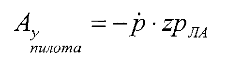
Следует отметить, что если предполагается, что элерон не только вызывает крен, но также и момент рыскания, то 
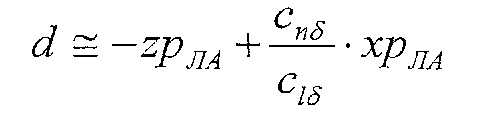
Если сnδ и Ciδ известны (например, в виде функции угла атаки), то это значение можно использовать вместе zP ЛА.If with nδ and C iδ are known (for example, as a function of the angle of attack), then this value can be used together z P ЛА .
Теперь изобретение будет описано посредством подробного описания нескольких вариантов осуществления изобретения. Очевидно, что в соответствии со знаниями специалистов в данной области техники можно конфигурировать другие варианты осуществления изобретения, не выходя при этом за рамки существа или технических параметров изобретения, а само изобретения ограничивается лишь терминами прилагаемой формулы изобретения.The invention will now be described by a detailed description of several embodiments of the invention. Obviously, in accordance with the knowledge of specialists in the given field of technology, other embodiments of the invention can be configured without going beyond the essence or technical parameters of the invention, and the invention itself is limited only by the terms of the attached claims.
Платформа тренажера может иметь хорошо известную конструкцию. Вариант осуществления такой платформы тренажера проиллюстрирован на Фиг.20. Настоящее изобретение также применимо к любой конструкции, имеющей, по меньшей мере, перечисленные ниже степени свободы: поперечное перемещение (качание) и угол крена. Только управление по этим степеням свободы адаптируется в соответствии с вариантами осуществления настоящего изобретения.The simulator platform may have a well-known design. An embodiment of such a simulator platform is illustrated in FIG. The present invention is also applicable to any structure having at least the degrees of freedom listed below: lateral movement (rocking) and roll angle. Only control over these degrees of freedom is adapted in accordance with embodiments of the present invention.
Новая концепция движения в соответствии с вариантами осуществления настоящего изобретения основана на трех фундаментальных изменениях или их комбинации:The new movement concept in accordance with embodiments of the present invention is based on three fundamental changes, or a combination thereof:
1°) Фиг.12: Фиг.12: корректируемые преобразования центроида;1 °) Fig. 12: Fig. 12: adjustable centroid transformations;
2°) Фиг.13: введение φкорр в канале крена;2 °) Fig.13: the introduction of φ corr in the roll channel;
3°) Фиг.14: разложение Ау и введение комплементарных фильтров.3 °) Fig. 14: decomposition of A y and the introduction of complementary filters.
Корректируемые преобразования центроида (Фиг.12)Adjustable Centroid Conversions (FIG. 12)
Преобразование центроида, описанное ранее (в разделе «Предшествующий уровень техники»), содержит важную погрешность. Поскольку движения платформы представляют собой отфильтрованные движения центроида «ц», а базисная точка Р пилота не находится в центроиде «ц», то в базисной точке Р пилота создаются ложные ускорения из-за существующей комбинации угловых ускорений платформы и расстояния, существующего в направлениях «z» и «х» между центроидом «ц» и базисной точкой Р пилота.The centroid transformation described earlier (in the Prior Art Section) contains an important error. Since the platform movements are filtered motions of the centroid “c” and the base point P of the pilot is not in the centroid “c”, false accelerations are created at the base point P of the pilot due to the existing combination of angular accelerations of the platform and the distance existing in the directions “z "And" x "between the centroid" c "and the base point P of the pilot.
Поэтому, в соответствии с вариантом осуществления настоящего изобретения, улучшенные преобразования являются следующими.Therefore, in accordance with an embodiment of the present invention, improved conversions are as follows.
1°) Вычислять удельные силы, действующие на ЛА, нужно не в гипотетическом месте «ц» нахождения центроида (как на Фиг.8), а в базисной точке Р пилота (Фиг.12):1 °) Calculate the specific forces acting on the aircraft, it is necessary not in the hypothetical place "c" of the centroid (as in Fig. 8), but in the base point P of the pilot (Fig. 12):
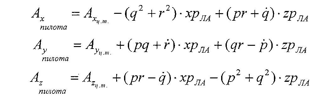
2°) Эти сигналы надлежит использовать вместе с угловыми скоростями в качестве входных сигналов для программы движения тренажера.2 °) These signals should be used together with angular velocities as input signals for the simulator movement program.
3°) Три выходных сигнала положения 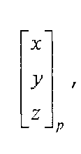
Пусть координаты базисной точки Р пилота по отношению к системе отсчета подвижной платформы имеют вид:Let the coordinates of the base point P of the pilot with respect to the reference frame of the moving platform have the form:
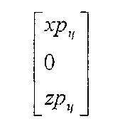
В соответствии с первоисточником Filip Van Biervliet, Technische Hogeschool Delft, "Ontwerp en evaluatie van stuurcommandosysteemregelwetten met de quickened display methode", bijlage 2 Ingenieursverslag, март 1982, между координатами точек Р и «ц» в системе отсчета фиксированной платформы поддерживается нижеследующее соотношение:According to the source Filip Van Biervliet, Technische Hogeschool Delft, "Ontwerp en evaluatie van stuurcommandosysteemregelwetten met de quickened display methode",
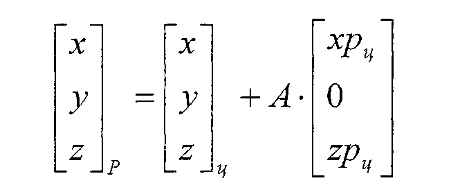
При этом А - матрица направляющих косинусов:Moreover, A is the matrix of guide cosines:

В результате:As a result:
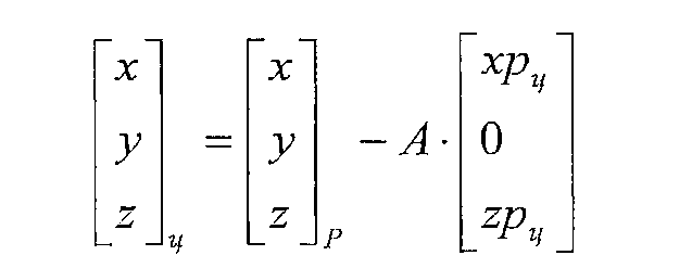
В направлении «у» имеем:In the direction of "y" we have:

Учитывая только влияние zPц и предполагая малые значения ψ, θ и φ, получаем:Given only the influence of z Pts and assuming small values of ψ, θ and φ, we obtain:
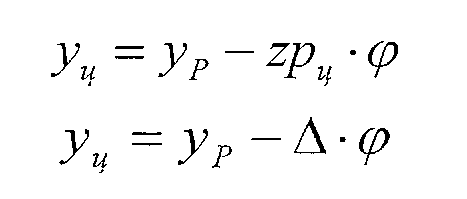
Введение φкорр в канале крена, Фиг.13The introduction of φ corr in the roll channel, Fig.13
Рассмотрим Фиг.13 в сравнении с Фиг.9. Эта компоновка фильтров предназначена для имитации угловых ускорений крена при сниженных или отсутствующих ложных поперечных удельных силах в соответствии с вариантом осуществления настоящего изобретения.Consider Fig.13 in comparison with Fig.9. This filter arrangement is intended to simulate roll angular accelerations with reduced or absent false transverse specific forces in accordance with an embodiment of the present invention.
Новой особенностью этой схемы является опережающая подача значения φкорр коррекции угла крена в канал крена. Значение φкорр коррекции угла крена пропорционально ложной поперечной удельной силе, вносимой фильтром, гасящим движение в направлении «у». Это низкочастотный сигнал. С физической точки зрения это означает, что платформа наклоняется назад пропорционально своему линейному замедлению (во многом точно так же, как в случае, когда официанту, вынужденному неожиданно остановиться, приходится наклонять свой поднос назад, чтобы не уронить стоящие на нем бокалы с напитками).A new feature of this scheme is the forward feed of the φ corr value of the roll angle correction to the roll channel. The value of φ corr correction of the angle of heel is proportional to the false transverse specific force introduced by the filter, damping the movement in the direction of "y". This is a low frequency signal. From a physical point of view, this means that the platform leans back in proportion to its linear deceleration (in much the same way as in the case when a waiter forced to stop unexpectedly has to tilt his tray back so as not to drop the glasses with drinks on it).
Передаточный коэффициент Ку поперечной координации (между 0 и 1) имеет смысл уменьшения поперечного качания тренажера.The gear ratio K for lateral coordination (between 0 and 1) makes sense to reduce the lateral swing of the simulator.
Это следуют из такой схемы вычислений:This follows from such a calculation scheme:

Это значит, что если передаточный коэффициент поперечной координации Ку=1, то направленная вдоль оси «у» составляющая удельной силы Аy=0, что означает полную координацию.This means that if the gear ratio of the transverse coordination To y = 1, then the component of the specific force A y = 0 directed along the axis "y", which means full coordination.
На Фиг.15 показан временной отклик для Ку=1. Он недвусмысленно показывает, что Аy=0. Вместе с тем, можно также заметить, что имеется несколько большее искажение в угловом ускорении крена (сравните Фиг.11.4 и Фиг.15.4).On Fig shows the time response for K y = 1. It clearly shows that A y = 0. However, it can also be noted that there is a slightly greater distortion in the angular acceleration of the roll (compare Fig. 11.4 and Fig. 15.4).
Если Ку=1, то очевидно, что те два тракта сигнала на Фиг.13, которые обозначены звездочкой, подавляют друг друга. Это означает, что можно урезать сложный φ-фильтр до φ-фильтра верхних частот, соединенного последовательно с фильтром, гасящим движение в направлении «у».If K y = 1, then it is obvious that those two signal paths in Fig. 13, which are indicated by an asterisk, suppress each other. This means that you can trim a complex φ-filter to a high-pass φ-filter, connected in series with a filter that dampens the motion in the "y" direction.
Это также является причиной, по которой фильтр, гасящий движение в направлении «у», предпочтительно выбирают как фильтр 1-го порядка, а не 2-го или более высокого порядка. Таким образом, сложный фильтр является фильтром 3-го порядка, а не 4-го порядка. Сложный φ-фильтр 4-го или более высокого порядка привел бы к еще большему искажению углового ускорения крена.This is also the reason why the filter damping the movement in the y direction is preferably selected as a 1st order filter, rather than a 2nd or higher order. Thus, a complex filter is a 3rd order filter, not a 4th order filter. A complex φ-filter of the fourth or higher order would lead to even greater distortion of the angular acceleration of the roll.
Уменьшение Ку до 0,7 или 0,8 уменьшает поперечную координацию; вместе с тем, это также приводит к меньшему искажению углового ускорения крена.Decreasing K y to 0.7 or 0.8 reduces lateral coordination; however, this also leads to less distortion in the angular acceleration of the roll.
С помощью теоремы Лапласа «о конечном значении» можно показать, что отклик ступеньки имеет вид:Using the Laplace theorem on the final value, it can be shown that the response of the step has the form:
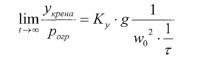
Это означает, что постоянная угловая скорость крена (возникающая из-за постоянного входного сигнала элеронов) приводит к постоянному смещению тренажера. Если бы порядок сложного фильтра, представляющий собой сумму порядков φ-фильтра верхних частот и фильтра, гасящего движение в направлении «у», был 4-м порядком или более высоким порядком, тоThis means that a constant angular roll speed (arising due to a constant input signal of ailerons) leads to a constant displacement of the simulator. If the order of the complex filter, which is the sum of the orders of the high-frequency φ-filter and the filter that dampens the motion in the y direction, is the 4th order or higher order, then
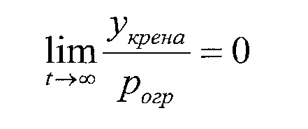
Таким образом, второе преимущество выбора сложного фильтра 3-го порядка, φ-фильтра верхних частот 2-го порядка и фильтра, гасящего движение в направлении «у», 1-го порядка или φ-фильтра верхних частот 1-го порядка и фильтра, гасящего движение в направлении «у», 2-го порядка заключается в том, что теперь после маневра тренажер готов к восприятию следующего маневра, т.е. обеспечивается возврат элеронов в нейтральное или противоположное положение.Thus, the second advantage is the choice of a complex 3rd-order filter, a 2nd-order high-pass φ filter and a 1st-order filter that suppresses movement in the y direction, or a 1st-order high-pass φ filter and a filter, extinguishing the movement in the direction of "y", the 2nd order is that now after the maneuver the simulator is ready to perceive the next maneuver, i.e. ailerons are returned to a neutral or opposite position.
Разложение Аy и введение комплементарных фильтров, Фиг.14The decomposition And y and the introduction of complementary filters, Fig.14
Поперечная удельная сила в кресле пилота в летательном аппарате представляет собой сумму поперечной удельной силы в фиксированной точке летательного аппарата, например в его центре тяжести, и ускорений, обусловленных положением пилота выше и спереди от этой фиксированной точки, т.е. центра тяжести, в соответствии с вышеуказанными формулами.The transverse specific gravity in the pilot's seat in an aircraft is the sum of the transverse specific gravity at a fixed point of the aircraft, for example at its center of gravity, and the accelerations due to the position of the pilot above and in front of this fixed point, i.e. center of gravity, in accordance with the above formulas.
Приемлемое приближение поперечной удельной силы уже задано в предыдущем разделе, где рассматривалось только ускорение, обусловленное только угловым ускорением:An acceptable approximation of the transverse specific force has already been set in the previous section, where only acceleration due to only angular acceleration was considered:

Можно показать, что комплементарные фильтры 2-го порядка нельзя использовать для сложного сигнала или для Ау в ц.т. Вместе с тем, при наличии сигналов р и r (которые представляют собой интегралы ускорений), их можно использовать в соответствии с вариантами осуществления настоящего изобретения в качестве входных сигналов в комплементарные фильтры 2-го порядка. Это показано на Фиг.14. Через классические фильтры по-прежнему посылается только поперечная удельная сила в фиксированной точке, например в центре тяжести.It can be shown that complementary second-order filters cannot be used for a complex signal or for A y in c.t. However, in the presence of signals p and r (which are acceleration integrals), they can be used in accordance with embodiments of the present invention as input signals to complementary second-order filters. This is shown in FIG. Through classical filters, only the transverse specific force at a fixed point, for example, at the center of gravity, is still sent.
Термин «комплементарные» (фильтры) означает, что сумма их передаточных функций равна 1, иными словами, входной сигнал считается представляющим их полное частотное содержимое. Начальный момент задается с поперечным смещением на нижних частотах по углу крена. Например, для удельной силы, обусловленной угловым ускорением крена:The term “complementary” (filters) means that the sum of their transfer functions is 1, in other words, the input signal is considered to represent their full frequency content. The initial moment is set with a lateral displacement at lower frequencies along the roll angle. For example, for the specific force due to the angular acceleration of the roll:
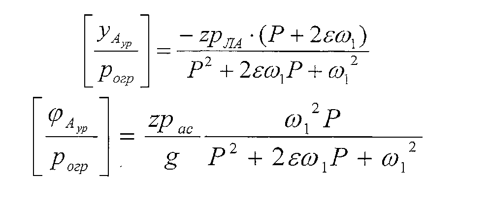
таким образомin this way

Также следует отметить, что для классического летательного аппарата zР ЛА<0.It should also be noted that for a classical aircraft z P LA <0.
С помощью теоремы Лапласа «о начальном значении» можно показать, чтоUsing the Laplace theorem on the initial value, we can show that
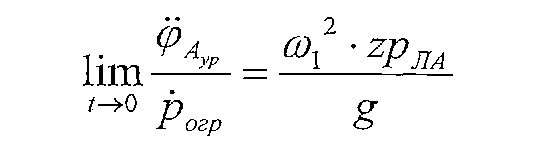
Это означает, что положительная ступенька в угловом ускорении (крена или рыскания) ЛА приводит к имеющему отрицательную ступеньку отклику углового ускорения тренажера. В случае имитации только маневра по крену, угловое ускорение крена в результате моделирования удельной силы уменьшает отклик углового ускорения крена из схемы отработки крена (Фиг.13). Поэтому важно выбрать ω1 как можно меньшего порядка, чтобы как можно больше уменьшить этот эффект.This means that a positive step in the angular acceleration (roll or yaw) of the aircraft leads to a negative step response of angular acceleration of the simulator. In the case of simulating only the roll maneuver, the angular acceleration of the roll as a result of the simulation of the specific force reduces the response of the angular acceleration of the roll from the roll mining circuit (Fig. 13). Therefore, it is important to choose ω 1 as small as possible in order to reduce this effect as much as possible.
Снова пользуясь теоремой Лапласа «о конечном значении», находим:Using Laplace's “finite value” theorem again, we find:
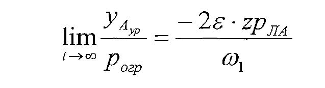
Это означает, что заданная угловая скорость крена или рыскания приведет к некоторому конечному поперечному положению тренажера. Отличительным преимуществом этого способа разложения сигнала и использования фильтров является то, что настройку этих фильтров можно адаптировать к типичным маневрам: фильтр рыскания можно адаптировать для ситуаций руления и отказа двигателя, фильтр крена - для ситуаций координированного разворота в сочетании с концепцией коррекции угла крена (введения φкорр).This means that the given angular velocity of the roll or yaw will lead to some final transverse position of the simulator. A distinctive advantage of this method of signal decomposition and the use of filters is that the settings of these filters can be adapted to typical maneuvers: the yaw filter can be adapted for situations of steering and engine failure, the roll filter for situations of coordinated reversal in combination with the concept of roll angle correction (introducing φ correspondent ).
Следует отметить, что положения и углы, поступающие из «канала крена» (Фиг.13) и «фильтров удельной силы Ау» (Фиг.14) приходится складывать друг с другом, чтобы получить суммарные положение и угол. Поскольку это происходит в положении базисной точки Р пилота, в соответствии с вариантами осуществления настоящего изобретения предпочтительно приводить эти параметры к положению центроида в соответствии с вышеуказанным уравнением (Фиг.12).It should be noted that the positions and angles coming from the “roll channel” (FIG. 13) and “specific force filters A y ” (FIG. 14) have to be folded together to obtain the total position and angle. Since this occurs at the position of the base point P of the pilot, in accordance with embodiments of the present invention, it is preferable to bring these parameters to the position of the centroid in accordance with the above equation (FIG. 12).
Обсуждение результатовThe discussion of the results
Маневр по кренуRoll maneuver
На Фиг.16 и 17 приведены несколько соответствующих общей концепции изменений во времени согласно вариантам осуществления настоящего изобретения, т.е. комбинация корректируемых преобразований центроида, введения коррекции угла крена и разложения Ау и добавления комплементарных фильтров. Максимальное поперечное перемещение выбрано равным типичному значению 1,20 м. Были сделаны следующие наблюдения.FIGS. 16 and 17 show several relevant general concepts of time changes according to embodiments of the present invention, i.e. a combination of adjustable centroid transformations, introducing a roll angle correction and decomposition A y and adding complementary filters. The maximum lateral displacement was chosen equal to a typical value of 1.20 m. The following observations were made.
1°) Если выбирают Ку=1 (Фиг.16), то восприятие Ау поперечной боковой силы в базисной точке Р пилота в тренажере точно пропорционально (передаточное отношение Kd) значению этой силы в летательном аппарате (Фиг.16.5).1 °) If you choose K y = 1 (Fig. 16), then the perception A of the lateral lateral force at the base point P of the pilot in the simulator is exactly proportional to (gear ratio K d ) the value of this force in the aircraft (Fig. 16.5).
2°) Если выбирают несколько меньшее Ку, например Ку=0,8 (Фиг.17), то происходит некоторое искажении сигнала Ау (Фиг.17.5), и при этом требуемое поперечное перемещение уменьшается (на Фиг.17.1 по сравнению с Фиг.16.1), а отклик углового ускорения крена φ немного увеличивается (на Фиг.17.4 по сравнению с Фиг.16.4).2 °) If you choose a slightly smaller K y , for example K y = 0.8 (Fig. 17), then there is some distortion of the signal A y (Fig. 17.5), and the required lateral movement is reduced (in Fig. 17.1 in comparison with Fig. 16.1), and the response of the angular acceleration of the roll φ is slightly increased (in Fig. 17.4 compared to Fig. 16.4).
Чтобы максимальное допустимое для тренажера значение никогда не превышалось, в соответствии с вариантами осуществления настоящего изобретения можно ввести функцию, ограничивающую угловую скорость (Фиг.18):So that the maximum allowable value for the simulator is never exceeded, in accordance with the variants of implementation of the present invention, you can enter a function that limits the angular velocity (Fig):
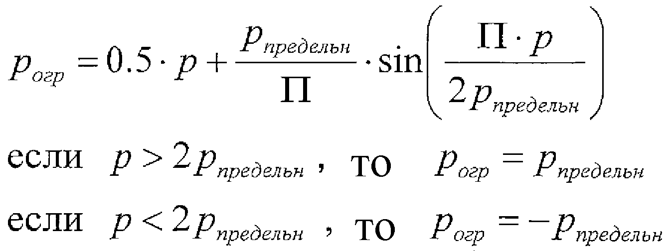
Вторая производная этой функции по времени непрерывна.The second time derivative of this function is continuous.
Наземный рулежный маневрGround taxiing maneuver
Изменения во времени не предусматриваются.No changes in time are foreseen.
В частности, при пониженных скоростях руления Ау в ц.т. имеет «низкочастотный характер», т.е. в боковых силах, действующих на пневматические шины основных (передних) колес, резких изменений нет. Следовательно, при таких скоростях выгоды от применения этой схемы окажутся наибольшими.In particular, at reduced taxiing speeds A y in c.t. has a "low frequency character", i.e. there are no sharp changes in the lateral forces acting on the pneumatic tires of the main (front) wheels. Therefore, at such speeds, the benefits of using this scheme will be greatest.
Вышеописанные варианты осуществления способа согласно настоящему изобретению можно воплотить в обрабатывающей системе 1500, такой как показанная на Фиг.19. На Фиг.19 показана одна конфигурация обрабатывающей системы 1500, которая включает в себя, по меньшей мере, один программируемый процессор 1503, подключенный к запоминающей подсистеме 1505, которая включает в себя запоминающее устройство, воплощенное, по меньшей мере, в одной из таких форм, как ОЗУ, ПЗУ и т.д. Можно предусмотреть и хранящую подсистему 1507, которая имеет, по меньшей мере, один дисковод для жестких дисков, и/или один дисковод для CD-ROM, и/или один дисковод для цифровых универсальных дисков (DVD). В некоторых воплощениях можно предусмотреть в качестве части подсистемы 1509 пользовательского интерфейса отображающую систему, клавиатуру и указательное устройство, дающие пользователю возможность вводить информацию вручную. Можно также предусмотреть порты для ввода и вывода данных. Возможно наличие и дополнительных элементов, таких как сетевые соединения, интерфейсы для различных устройств и т.п., но они не показаны на Фиг.19. Различные элементы обрабатывающей системы 1500 могут быть соединены по-разному, включая соединения посредством подсистемы 1513 шин, которая для простоты показана на Фиг.19 в виде одной-единственной шины, но специалистам в данной области техники должно быть ясно, что можно предусмотреть систему, имеющую, по меньшей мере, одну шину. Запоминающие устройство запоминающей подсистемы 1505 может в течение некоторого момента времени содержать часть набора команд, которые при их выполнении на обрабатывающей системе 1500 воплощают этап(ы) описанных здесь вариантов осуществления способа, или весь такой набор (для любого из двух случаев это показано посредством позиции 1511). Таким образом, хотя обрабатывающая система 1500, такая как показанная на Фиг.19, известна, система, которая включает в себя команды для воплощения аспектов настоящего изобретения, не известна, и поэтому Фиг.19 не обозначена, как отображающая известный уровень техники.The above-described embodiments of the method according to the present invention can be implemented in a
Следует отметить, процессор 1503 или процессоры может или могут быть процессором или процессорами общего назначения, процессором или процессорами специального назначения, а его или их назначением может быть включение в состав некоторого устройства, например микросхемы, которая имеет другие компоненты, выполняющие другие функции. Таким образом, один или несколько аспектов настоящего изобретения можно воплотить в цифровых электронных схемах или в компьютерных аппаратных средствах, программно-аппаратных средствах, программных средствах или их комбинациях. Кроме того, аспекты изобретения можно реализовать с помощью программируемого процессора, выполняющего команды, позволяющие выполнить функции этих аспектов изобретения, например, путем выполнения операций над входными данными и генерирования выходных данных.It should be noted that the
Вышеописанная обрабатывающая система может быть предназначена для использования в пилотажном тренажере, например, таком, как показанный на Фиг.20.The above processing system may be intended for use in an aerobatic simulator, for example, such as that shown in FIG.
Следует понять, что хотя здесь рассмотрены предпочтительные варианты осуществления способов и устройств, соответствующих настоящему изобретению, в рамках объема притязаний и существа этого изобретения возможно проведение изменений или модификаций в его форме и деталях.It should be understood that although preferred embodiments of the methods and devices of the present invention are discussed herein, within the scope of the claims and the merits of this invention, it is possible to make changes or modifications in its form and details.
Claims (11)
вычисляют угол (φ) крена тренажера в соответствии с углом крена имитируемого летательного аппарата путем коррекции первоначально вычисленного значения (φвч) угла (φ) крена с коэффициентом (φкорр) коррекции, пропорциональным поперечной удельной силе, вносимой гасящим фильтром, используемым во время вычисления выравнивания поперечного положения (у) тренажера в соответствии с направлением силы тяжести Земли, и/или
разлагают удельную силу (Ау пилота), действующую в поперечном направлении в базисной точке пилота в имитируемом летательном аппарате, на первую составляющую и вторую составляющую, причем первая составляющая связана с удельной силой (Ау) в фиксированной точке имитируемого летательного аппарата, а вторая составляющая имеет первый член, связанный с ускорениями, обуславливаемыми рысканием (r), и второй член, связанный с угловыми ускорениями крена (р), в соответствии с формулой:

где хрЛА - координата «х» базисной точки пилота в системе координат, имеющей начало в упомянутой фиксированной точке имитируемого летательного аппарата, а zрЛА - координата «z» базисной точки пилота в упомянутой системе координат,


фильтруют первую составляющую (Ау) посредством двух фильтров: фильтр верхних частот и фильтр нижних частот;
параллельно фильтруют каждый из членов второй составляющей с помощью набора из первого и второго комплементарных фильтров, причем комплементарные фильтры являются фильтрами, сумма передаточных функций которых равна единице,
используют сумму выходного сигнала фильтра верхних частот и выходных сигналов первых комплементарных фильтров каждого набора для вычисления желаемого поперечного положения (у) тренажера, а также используют сумму выходного сигнала фильтра нижних частот и выходных сигналов вторых комплементарных фильтров каждого набора для вычисления желаемого угла (φ) крена тренажера.1. A method of controlling the movements of the flight simulator, providing linear and angular accelerations perceived by the pilot sitting in the pilot's seat, as a result of which the angular velocity (p) of the roll and the angular velocity (r) of yaw, as well as the specific force (A y ) in the transverse direction, calculated in accordance with the model of the simulated aircraft at a fixed point in the simulated aircraft, are converted by the program of movement into the transverse position (y) and the angle (φ) of the simulator roll, characterized in that it includes the steps , where:
calculate the roll angle (φ) of the simulator in accordance with the roll angle of the simulated aircraft by correcting the initially calculated value (φ rf ) of the roll angle (φ) with a correction coefficient (φ corr ) proportional to the transverse specific force introduced by the quenching filter used during calculation alignment of the transverse position (s) of the simulator in accordance with the direction of the Earth's gravity, and / or
decompose the specific force (A for the pilot ), acting in the transverse direction at the base point of the pilot in the simulated aircraft, into the first component and the second component, the first component being related to the specific force (A y ) at a fixed point in the simulated aircraft, and the second component has a first term associated with yaw accelerations (r), and a second term associated with angular roll accelerations (p), in accordance with the formula:
where xp LA is the coordinate "x" of the base point of the pilot in the coordinate system having a origin at the fixed point of the simulated aircraft, and zr LA is the coordinate "z" of the base point of the pilot in the coordinate system,
filtering the first component (A y ) by means of two filters: a high-pass filter and a low-pass filter;
in parallel, each of the members of the second component is filtered using a set of first and second complementary filters, the complementary filters being filters, the sum of the transfer functions of which is unity,
use the sum of the output signal of the high-pass filter and the output signals of the first complementary filters of each set to calculate the desired lateral position (s) of the simulator, and also use the sum of the output signal of the low-pass filter and the output signals of the second complementary filters of each set to calculate the desired angle (φ) simulator.

где φвч - угол крена тренажера, пропущенный через фильтр верхних частот;
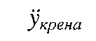
g - постоянная силы тяжести Земли;
Ку - коэффициент усиления поперечной координации;
φкрена - соответствует углу крена тренажера, получаемому в результате углового ускорения крена или угловой скорости крена имитируемого летательного аппарата.2. A method according to claim 1, characterized in that the calculation of the roll angle (φ roll) of the simulator includes using a mathematical transformation, providing anticipatory feed correction angle (φ corr) in the roll angle transformation function according to the formulas:
where φ RF is the tilt angle of the simulator, passed through a high-pass filter;
g is the constant of the Earth's gravity;
To y - gain transverse coordination;
φ roll - corresponds to the roll angle of the simulator obtained as a result of the angular acceleration of the roll or the angular roll speed of a simulated aircraft.
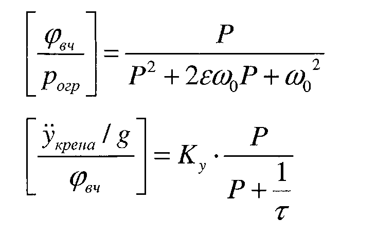
где Рогр - входная угловая скорость крена, ограничиваемая посредством понижающего настроечного коэффициента усиления Kd и опционально посредством функции, ограничивающей угловую скорость крена таким образом, что для ступеньки в сигнале управления элеронами боковое перемещение тренажера имеет конечное значение, и где Р - оператор Лапласа.5. The method of claim 2, wherein the mathematical transformation involves a highpass filter of 2nd order for the roll angle (φ roll) and the filter of the 1st order, blanking movement in the direction of "y", in accordance with the following formulas gear functions:
where P ogre is the input angular roll speed, limited by a lower tuning gain K d and optionally by a function that limits the angular roll speed so that for a step in the aileron control signal the lateral movement of the simulator has a finite value, and where P is the Laplace operator.
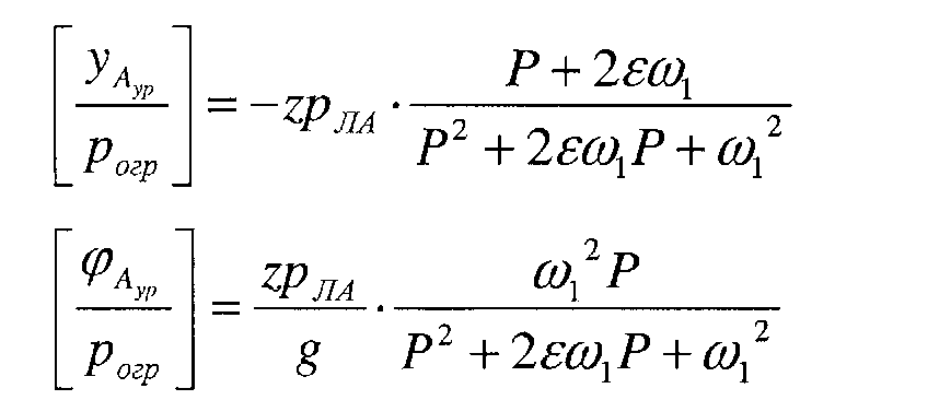
и
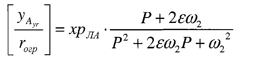
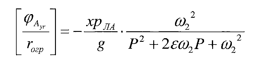
где рогр и rогр - входные угловая скорость крена и угловая скорость рыскания соответственно, ограничиваемые посредством понижающих настроечных коэффициентов усиления Kd и Кr соответственно, и опционально посредством функции, ограничивающей угловую скорость, а Р - оператор Лапласа.7. The method according to claim 1, in which the second component of the specific gravity in the transverse direction is obtained by four additional filters: a first set of two complementary filters for angular roll acceleration and a second set of two complementary filters for angular acceleration of yaw, with each set complementary filters, one is used to control the lateral deviation of the simulator, and the other to control the roll angle of the simulator, in accordance with the following transfer function formulas:
and
where r ogre and r ogre are the input angular roll speed and the angular yaw rate, respectively, limited by decreasing tuning gains K d and K r, respectively, and optionally by the function limiting the angular velocity, and P is the Laplace operator.
контроллер содержит любые компоненты из таких, как:
первый вычислительный блок, выполненный с возможностью вычисления угла (φ) крена тренажера, обуславливаемого углом крена имитируемого летательного аппарата, путем коррекции первоначально вычисленного значения (φвч) угла (φ) крена с коэффициентом (φкорр) коррекции, пропорциональным поперечной удельной силе, вносимой гасящим фильтром, используемым во время вычисления выравнивания поперечного положения (у) тренажера в соответствии с направлением силы тяжести Земли, и/или
второй вычислительный блок, выполненный с возможностью разложения удельной силы (Ау пилота), действующей в поперечном направлении в базисной точке пилота в имитируемом летательном аппарате, на первую составляющую и вторую составляющую, причем первая составляющая связана с удельной силой (Ау) в фиксированной точке имитируемого летательного аппарата, а вторая составляющая имеет первый член, связанный с ускорениями, обуславливаемыми рысканием (r), и второй член, связанный с угловыми ускорениями крена (р), в соответствии с формулой:

где хрЛА - координата «х» базисной точки (Р) пилота в системе координат, имеющей начало в упомянутой фиксированной точке имитируемого летательного аппарата, а zрЛА - координата «z» базисной точки пилота в упомянутой системе координат,


фильтр верхних частот и фильтр нижних частот для фильтрации первой составляющей (Ау);
два набора, каждый из которых состоит из первого и второго комплементарных фильтров, причем комплементарные фильтры являются фильтрами, сумма передаточных функций которых равна единице, для параллельной фильтрации каждого из членов второй составляющей,
сумматор для суммирования выходного сигнала фильтра верхних частот и выходных сигналов первых комплементарных фильтров каждого набора для вычисления желаемого поперечного положения (у) тренажера, а также сумматор для суммирования выходного сигнала фильтра нижних частот и выходных сигналов вторых комплементарных фильтров каждого набора для вычисления желаемого угла (φ) крена тренажера.10. A controller for controlling the movements of the flight simulator, providing linear and angular accelerations, perceived by the pilot sitting in the pilot's seat, as a result of which the angular velocity (p) of the roll and the angular velocity (r) of yaw, as well as the specific force (A y ) in the transverse direction calculated in accordance with the model of the simulated aircraft at a fixed point in the simulated aircraft are converted by the movement program into the transverse position (y) and the angle (φ) of the simulator roll, while
the controller contains any of the following components:
the first computing unit configured to calculate the roll angle (φ) of the simulator, determined by the roll angle of the simulated aircraft, by correcting the originally calculated value (φ rf ) of the roll angle (φ) with a correction coefficient (φ corr ) proportional to the transverse specific force introduced extinguishing filter used during the calculation of the alignment of the transverse position (y) of the simulator in accordance with the direction of the Earth's gravity, and / or
a second computing unit configured to decompose the specific force (A of the pilot ), acting in the transverse direction at the base point of the pilot in the simulated aircraft, into a first component and a second component, the first component being related to the specific force (A y ) at a fixed point simulated aircraft, and the second component has a first term associated with accelerations due to yaw (r), and a second term associated with angular accelerations of the roll (p), in accordance with the formula:
where xp LA is the coordinate "x" of the base point (P) of the pilot in the coordinate system having a origin at the fixed point of the simulated aircraft, and zp LA is the coordinate "z" of the base point of the pilot in the coordinate system,
a high-pass filter and a low-pass filter for filtering the first component (A y );
two sets, each of which consists of the first and second complementary filters, and the complementary filters are filters, the sum of the transfer functions of which is equal to one, for parallel filtering of each of the members of the second component,
an adder for summing the output signal of the high-pass filter and the output signals of the first complementary filters of each set to calculate the desired transverse position (s) of the simulator, as well as an adder for summing the output signal of the low-pass filter and the outputs of the second complementary filters of each set to calculate the desired angle (φ ) roll of the simulator.
второй вычислительный блок, выполненный с возможностью разложения удельной силы (Ау пилота), действующей в поперечном направлении в базисной точке пилота в имитируемом летательном аппарате, на первую составляющую и вторую составляющую, причем первая составляющая связана с удельной силой (Ау) в фиксированной точке имитируемого летательного аппарата, а вторая составляющая имеет первый член, связанный с ускорениями, обуславливаемыми рысканием (r), и второй член, связанный с угловыми ускорениями крена (р), в соответствии с формулой:

где хрЛА - координата «х» базисной точки (Р) пилота в системе координат, имеющей начало в упомянутой фиксированной точке имитируемого летательного аппарата, а zрЛА - координата «z» базисной точки пилота в упомянутой системе координат,


фильтр верхних частот и фильтр нижних частот для фильтрации первой составляющей (Ау);
два набора, каждый из которых состоит из первого и второго комплементарных фильтров, причем комплементарные фильтры являются фильтрами, сумма передаточных функций которых равна единице, для параллельной фильтрации каждого из членов второй составляющей,
сумматор для суммирования выходного сигнала фильтра верхних частот и выходных сигналов первых из комплементарных фильтров каждого набора для вычисления желаемого поперечного положения (у) тренажера, а также сумматор для суммирования выходного сигнала фильтра нижних частот и выходных сигналов вторых из комплементарных фильтров каждого набора для вычисления желаемого угла (φ) крена тренажера. 11. Flight simulator, made with the possibility of making controlled movements involving linear and angular accelerations, perceived by the pilot sitting in the pilot's seat, as a result of which the angular velocity (p) of the roll and angular (r) speed of yaw, as well as the specific force (A y ) in the transverse direction, calculated in accordance with the model of the simulated aircraft at a fixed point in the simulated aircraft, are converted by the movement program into the transverse position (y) and the roll angle (φ) of the simulator, while the pilot An important simulator contains any components such as: a first computing unit configured to calculate the roll angle (φ) of the simulator, determined by the roll angle of the simulated aircraft, by correcting the initially calculated value (φ rf ) of the roll angle (φ) with a coefficient (φ corr ) corrections proportional to the transverse specific force introduced by the quenching filter used during the calculation of the alignment of the transverse position (y) of the simulator in accordance with the direction of the Earth's gravity, and / or
a second computing unit configured to decompose the specific force (A of the pilot ), acting in the transverse direction at the base point of the pilot in the simulated aircraft, into a first component and a second component, the first component being related to the specific force (A y ) at a fixed point simulated aircraft, and the second component has a first term associated with accelerations due to yaw (r), and a second term associated with angular accelerations of the roll (p), in accordance with the formula:
where xp LA is the coordinate "x" of the base point (P) of the pilot in the coordinate system having a origin at the fixed point of the simulated aircraft, and zp LA is the coordinate "z" of the base point of the pilot in the coordinate system,
a high-pass filter and a low-pass filter for filtering the first component (A y );
two sets, each of which consists of the first and second complementary filters, and the complementary filters are filters, the sum of the transfer functions of which is equal to one, for parallel filtering of each of the members of the second component,
an adder for summing the output signal of the high-pass filter and the output signals of the first of the complementary filters of each set to calculate the desired transverse position (s) of the simulator, as well as an adder for summing the output signal of the low-pass filter and the output signals of the second of the complementary filters of each set to calculate the desired angle (φ) roll simulator.
Applications Claiming Priority (2)
| Application Number | Priority Date | Filing Date | Title |
|---|---|---|---|
| EP05447231 | 2005-10-12 | ||
| EP05447231.1 | 2005-10-12 |
Publications (2)
| Publication Number | Publication Date |
|---|---|
| RU2008118206A RU2008118206A (en) | 2009-11-20 |
| RU2425409C2 true RU2425409C2 (en) | 2011-07-27 |
Family
ID=36204350
Family Applications (1)
| Application Number | Title | Priority Date | Filing Date |
|---|---|---|---|
| RU2008118206/08A RU2425409C2 (en) | 2005-10-12 | 2006-10-12 | Method of controlling movement of flight simulator and flight simulator implementing said method |
Country Status (11)
| Country | Link |
|---|---|
| US (1) | US8393902B2 (en) |
| EP (1) | EP1946193B2 (en) |
| JP (1) | JP5715324B2 (en) |
| CN (1) | CN101305328B (en) |
| AT (1) | ATE462163T1 (en) |
| CA (1) | CA2625103C (en) |
| DE (1) | DE602006013179D1 (en) |
| ES (1) | ES2342901T5 (en) |
| PT (1) | PT1946193E (en) |
| RU (1) | RU2425409C2 (en) |
| WO (1) | WO2007042290A1 (en) |
Cited By (1)
| Publication number | Priority date | Publication date | Assignee | Title |
|---|---|---|---|---|
| RU2820152C1 (en) * | 2024-01-30 | 2024-05-30 | Федеральное автономное учреждение "Центральный аэрогидродинамический институт имени профессора Н.Е. Жуковского" (ФАУ "ЦАГИ") | Method of aircraft flight dynamics simulation |
Families Citing this family (29)
| Publication number | Priority date | Publication date | Assignee | Title |
|---|---|---|---|---|
| US8827709B1 (en) * | 2008-05-08 | 2014-09-09 | ACME Worldwide Enterprises, Inc. | Dynamic motion seat |
| NL2005174C2 (en) | 2010-07-29 | 2012-01-31 | E2M Technologies B V | Movement-simulator. |
| US8653780B2 (en) * | 2010-09-28 | 2014-02-18 | The Boeing Company | Integrated upsampler and filtering for multi-rate controller for electro-mechanical flight actuation system |
| TWI448969B (en) * | 2011-02-16 | 2014-08-11 | Chang Jung Christian University | Three - axis dynamic simulation platform system and its control method |
| CN102390544B (en) * | 2011-09-15 | 2013-11-13 | 北京航空航天大学 | Motion-linked cabin layout converting device for airplane simulator |
| US8874286B2 (en) | 2012-02-27 | 2014-10-28 | Textron Innovations, Inc. | Yaw damping system and method for aircraft |
| US8620492B2 (en) * | 2012-02-27 | 2013-12-31 | Textron Innovations Inc. | Yaw damping system and method for aircraft |
| DE102012103870B4 (en) * | 2012-04-19 | 2016-10-13 | Deutsches Zentrum für Luft- und Raumfahrt e.V. | Movement system state |
| US9536446B2 (en) * | 2012-12-03 | 2017-01-03 | Dynamic Motion Group Gmbh | Motion simulation system controller and associated methods |
| US9259657B2 (en) | 2012-12-03 | 2016-02-16 | Dynamic Motion Group Gmbh | Motion simulation system and associated methods |
| US9242181B2 (en) | 2012-12-03 | 2016-01-26 | Dynamic Motion Group Gmbh | Amusement park elevator drop ride system and associated methods |
| EP2854120A1 (en) | 2013-09-26 | 2015-04-01 | Thomson Licensing | Method and device for controlling a haptic device |
| DE102015102459B4 (en) * | 2015-02-20 | 2016-11-03 | Deutsches Zentrum für Luft- und Raumfahrt e.V. | Method and device for driving a simulator |
| US9837939B1 (en) * | 2015-04-01 | 2017-12-05 | Lockheed Martin Corporation | System and method for providing vibration isolation by magnetic levitation |
| US9845146B2 (en) * | 2015-10-23 | 2017-12-19 | The Boeing Company | Zoom climb prevention system for enhanced performance |
| US11288340B2 (en) * | 2016-03-31 | 2022-03-29 | Cae Inc. | Dynamically updating a model associated to a simulated interactive object |
| FR3052861B1 (en) * | 2016-06-20 | 2018-07-13 | Ixblue | METHOD FOR COMPENSATION OF CORIOLIS, CENTRIFUGAL AND GRAVITY COUPLES IN A MOTION SIMULATOR, MOTION SIMULATOR SYSTEM |
| CN106403937B (en) * | 2016-07-07 | 2023-05-26 | 上海机电工程研究所 | Navigation information filtering method for improving alignment accuracy of movable base |
| CN108495789A (en) * | 2017-05-23 | 2018-09-04 | 深圳市大疆创新科技有限公司 | Installation error detection method, equipment and the unmanned plane of accelerometer |
| CN107150816B (en) * | 2017-06-06 | 2019-04-26 | 哈尔滨工业大学 | A metamorphic aircraft simulation device |
| CN108388279B (en) * | 2018-02-12 | 2021-09-17 | 浙江中控技术股份有限公司 | Control method and device for high-speed rotating mechanical equipment |
| KR102239618B1 (en) | 2019-09-17 | 2021-04-12 | 김경환 | Control system for virtual reality driver simulator |
| IT202000005671A1 (en) * | 2020-03-17 | 2021-09-17 | Faiveley Transport Italia Spa | Procedure for estimating a longitudinal speed of at least one railway vehicle |
| CN111816023B (en) * | 2020-07-27 | 2022-05-03 | 中国工程物理研究院总体工程研究所 | Kinematics method of four-axis manned centrifugal machine |
| CN112307572B (en) * | 2020-07-27 | 2022-10-21 | 中国工程物理研究院总体工程研究所 | Overload and attitude simulation method for dynamic distribution of human centrifuge perception error |
| KR102499292B1 (en) * | 2020-12-01 | 2023-02-13 | 주식회사 젠스템 | A method for controlling motion flatform with queing algorithm based on operation range margin |
| RU2768310C1 (en) * | 2021-07-07 | 2022-03-23 | Акционерное общество "Российская самолетостроительная корпорация "МиГ" (АО "РСК "МиГ") | Course channel aircraft control system |
| CN113674582A (en) * | 2021-08-08 | 2021-11-19 | 中国航空工业集团公司沈阳飞机设计研究所 | Six-degree-of-freedom motion platform acceleration simulation method |
| CN116552802B (en) * | 2023-06-16 | 2025-09-16 | 中国飞机强度研究所 | Method for monitoring ground lifting pose of whole aircraft in aircraft structural strength test |
Citations (5)
| Publication number | Priority date | Publication date | Assignee | Title |
|---|---|---|---|---|
| US3732630A (en) * | 1970-10-21 | 1973-05-15 | Us Navy | Visual simulator |
| RU2037209C1 (en) * | 1992-02-14 | 1995-06-09 | Летно-исследовательский институт им.М.М.Громова | Training apparatus |
| US5433608A (en) * | 1991-03-20 | 1995-07-18 | Thomson Training & Simulation Limited | Vehicle simulator and method for controlling a vehicle simulator |
| WO1998058509A1 (en) * | 1997-06-16 | 1998-12-23 | Swisscom Ag | Chip card and method for communication between an external device and a chip card |
| RU2178721C2 (en) * | 2000-03-01 | 2002-01-27 | Новолодский Иван Дмитриевич | Attraction-exerciser |
Family Cites Families (16)
| Publication number | Priority date | Publication date | Assignee | Title |
|---|---|---|---|---|
| US3678256A (en) * | 1970-10-05 | 1972-07-18 | Mc Donnell Douglas Corp | Performance and failure assessment monitor |
| US3989208A (en) * | 1972-11-16 | 1976-11-02 | The Boeing Company | Thrust and flight path control decoupling system |
| US4956780A (en) * | 1988-12-08 | 1990-09-11 | The Boeing Company | Flight path angle command flight control system for landing flare |
| US5353242A (en) * | 1988-12-28 | 1994-10-04 | Veda Incorporated | Motion base control process and operator perceptual simulator |
| US5179525A (en) * | 1990-05-01 | 1993-01-12 | University Of Florida | Method and apparatus for controlling geometrically simple parallel mechanisms with distinctive connections |
| US5195700A (en) * | 1991-08-28 | 1993-03-23 | United Technologies Corporation | Low speed model following velocity command system for rotary wing aircraft |
| JPH08248872A (en) | 1995-03-08 | 1996-09-27 | Toyota Motor Corp | Driving simulation test equipment |
| US5711670A (en) * | 1995-11-13 | 1998-01-27 | Barr; Craig Kevin | Motion-base ride simulator with improved passenger loading and unloading method and apparatus |
| US5762068A (en) * | 1995-11-27 | 1998-06-09 | Quinton Instrument Company | ECG filter and slew rate limiter for filtering an ECG signal |
| JP3716134B2 (en) * | 1999-07-13 | 2005-11-16 | 株式会社日立製作所 | Oscillation device operation command data generation method and oscillation device |
| JP2003186387A (en) * | 2001-12-20 | 2003-07-04 | Masao Nagai | Method for controlling oscillation device for driving simulator |
| US7236914B1 (en) * | 2002-02-22 | 2007-06-26 | Microsoft Corporation | Integrated aircraft flight dynamics prediction and simulation |
| JP4104362B2 (en) * | 2002-03-27 | 2008-06-18 | 泰敬 田川 | Control method of shaking device for sensory acceleration simulation device |
| US7033176B2 (en) * | 2002-07-17 | 2006-04-25 | Powergrid Fitness, Inc. | Motion platform system and method of rotating a motion platform about plural axes |
| US6772080B2 (en) * | 2002-12-24 | 2004-08-03 | The Boeing Company | System and method for kinematic consistency processing |
| US7496865B2 (en) * | 2005-05-20 | 2009-02-24 | Chung Yuan Christian University | OTA-based high-order filters |
-
2006
- 2006-10-12 AT AT06806200T patent/ATE462163T1/en not_active IP Right Cessation
- 2006-10-12 PT PT06806200T patent/PT1946193E/en unknown
- 2006-10-12 JP JP2008534934A patent/JP5715324B2/en active Active
- 2006-10-12 ES ES06806200T patent/ES2342901T5/en active Active
- 2006-10-12 EP EP06806200A patent/EP1946193B2/en active Active
- 2006-10-12 CN CN2006800378042A patent/CN101305328B/en active Active
- 2006-10-12 DE DE602006013179T patent/DE602006013179D1/en active Active
- 2006-10-12 RU RU2008118206/08A patent/RU2425409C2/en active
- 2006-10-12 WO PCT/EP2006/009841 patent/WO2007042290A1/en not_active Ceased
- 2006-10-12 CA CA2625103A patent/CA2625103C/en active Active
- 2006-10-12 US US12/083,496 patent/US8393902B2/en active Active
Patent Citations (5)
| Publication number | Priority date | Publication date | Assignee | Title |
|---|---|---|---|---|
| US3732630A (en) * | 1970-10-21 | 1973-05-15 | Us Navy | Visual simulator |
| US5433608A (en) * | 1991-03-20 | 1995-07-18 | Thomson Training & Simulation Limited | Vehicle simulator and method for controlling a vehicle simulator |
| RU2037209C1 (en) * | 1992-02-14 | 1995-06-09 | Летно-исследовательский институт им.М.М.Громова | Training apparatus |
| WO1998058509A1 (en) * | 1997-06-16 | 1998-12-23 | Swisscom Ag | Chip card and method for communication between an external device and a chip card |
| RU2178721C2 (en) * | 2000-03-01 | 2002-01-27 | Новолодский Иван Дмитриевич | Attraction-exerciser |
Cited By (1)
| Publication number | Priority date | Publication date | Assignee | Title |
|---|---|---|---|---|
| RU2820152C1 (en) * | 2024-01-30 | 2024-05-30 | Федеральное автономное учреждение "Центральный аэрогидродинамический институт имени профессора Н.Е. Жуковского" (ФАУ "ЦАГИ") | Method of aircraft flight dynamics simulation |
Also Published As
| Publication number | Publication date |
|---|---|
| ATE462163T1 (en) | 2010-04-15 |
| EP1946193B1 (en) | 2010-03-24 |
| JP5715324B2 (en) | 2015-05-07 |
| CN101305328B (en) | 2012-10-17 |
| US20090047636A1 (en) | 2009-02-19 |
| DE602006013179D1 (en) | 2010-05-06 |
| RU2008118206A (en) | 2009-11-20 |
| HK1123612A1 (en) | 2009-06-19 |
| EP1946193B2 (en) | 2013-01-30 |
| ES2342901T5 (en) | 2013-05-28 |
| WO2007042290A1 (en) | 2007-04-19 |
| US8393902B2 (en) | 2013-03-12 |
| CA2625103C (en) | 2014-07-22 |
| ES2342901T3 (en) | 2010-07-16 |
| CN101305328A (en) | 2008-11-12 |
| PT1946193E (en) | 2010-06-23 |
| JP2009511968A (en) | 2009-03-19 |
| US20110070564A2 (en) | 2011-03-24 |
| CA2625103A1 (en) | 2007-04-19 |
| EP1946193A1 (en) | 2008-07-23 |
Similar Documents
| Publication | Publication Date | Title |
|---|---|---|
| JP5715324B2 (en) | Flight simulator movement control method and flight simulator implementing such a method | |
| Padfield et al. | Flight simulation in academia HELIFLIGHT in its first year of operation at the University of Liverpool | |
| EP3074103B1 (en) | Motion simulation system controller and associated methods | |
| Garrett et al. | Driving simulator motion cueing algorithms–a survey of the state of the art | |
| Hosman et al. | Integrated design of flight simulatormotion cueing systems | |
| US20250335648A1 (en) | State dependent motion cueing | |
| Weiß | Control of a dynamic driving simulator: Time-variant motion cueing algorithms and prepositioning | |
| Chang et al. | Optimal motion cueing for 5-DOF motion simulations via a 3-DOF motion simulator | |
| Zeyada et al. | Computer-aided assessment of flight simulator fidelity | |
| Parrish et al. | Comparison of a linear and a nonlinear washout for motion simulators utilizing objective and subjective data from ctol transport landing approaches | |
| Ackerman et al. | Pilot-in-the-loop flight simulator for NASA’s Transport Class Model | |
| Hosman et al. | Integrated design of the motion cueing system for a Wright Flyer Simulator | |
| Beukers et al. | Investigation into pilot perception and control during Decrab maneuvers in simulated flight | |
| Popovici et al. | Time-varying manual control identification in a stall recovery task under different simulator motion conditions | |
| Zaal et al. | Identification of multimodal pilot control behavior in real flight | |
| HK1123612B (en) | Method to control the movements of a flight simulator and flight simulator implementing such method | |
| Bukal et al. | An adaptive model predictive control based motion drive algorithm | |
| CN120805520B (en) | Flight parameter reproduction and simulated flight simulation state instant switching control method, system and medium | |
| Lee et al. | How to design intuitive flight controls for novice onboard operators? | |
| Zhou et al. | Washout algorithm for 3-DOF driving simulator based on feature enhancement and attitude smoothing | |
| Linklater et al. | Exploring the large amplitude multi-mode aerospace research simulator's motion drive algorithms | |
| Tang et al. | An Improved Washout Algorithm for UPRT | |
| Sadraei et al. | Understanding cue utility in controlled evasive driving manoeuvres: optimizing vestibular cues for simulator & human abilities | |
| Sadraei | Driving Simulator Motion Cueing Assessment: A Platform Design Perspective | |
| Hosman | The use of pilot models to support flight simulation: the sky is the envelope |
Legal Events
| Date | Code | Title | Description |
|---|---|---|---|
| PC41 | Official registration of the transfer of exclusive right |
Effective date: 20210203 |
|
| PC41 | Official registration of the transfer of exclusive right |
Effective date: 20210329 |