RU2425778C2 - Method to glue elements for aircraft without application of autoclave - Google Patents
Method to glue elements for aircraft without application of autoclave Download PDFInfo
- Publication number
- RU2425778C2 RU2425778C2 RU2008132424/11A RU2008132424A RU2425778C2 RU 2425778 C2 RU2425778 C2 RU 2425778C2 RU 2008132424/11 A RU2008132424/11 A RU 2008132424/11A RU 2008132424 A RU2008132424 A RU 2008132424A RU 2425778 C2 RU2425778 C2 RU 2425778C2
- Authority
- RU
- Russia
- Prior art keywords
- stringers
- vacuum
- elements
- adhesive film
- film
- Prior art date
Links
- 238000000034 method Methods 0.000 title claims abstract description 47
- 239000003292 glue Substances 0.000 title description 3
- 239000002313 adhesive film Substances 0.000 claims abstract description 34
- 239000004744 fabric Substances 0.000 claims abstract description 6
- 239000003822 epoxy resin Substances 0.000 claims abstract description 5
- 229920000647 polyepoxide Polymers 0.000 claims abstract description 5
- 239000011248 coating agent Substances 0.000 claims description 13
- 229910000838 Al alloy Inorganic materials 0.000 claims description 9
- 238000000576 coating method Methods 0.000 claims description 9
- 239000002131 composite material Substances 0.000 claims description 8
- 238000007747 plating Methods 0.000 claims 1
- 238000004519 manufacturing process Methods 0.000 abstract description 17
- 238000004026 adhesive bonding Methods 0.000 abstract description 11
- 239000000126 substance Substances 0.000 abstract description 4
- 239000012080 ambient air Substances 0.000 abstract description 3
- 238000010276 construction Methods 0.000 abstract description 3
- 230000000694 effects Effects 0.000 abstract description 2
- 229920001296 polysiloxane Polymers 0.000 description 15
- 230000001070 adhesive effect Effects 0.000 description 10
- 239000000463 material Substances 0.000 description 10
- 239000000853 adhesive Substances 0.000 description 9
- 239000002390 adhesive tape Substances 0.000 description 9
- 239000003570 air Substances 0.000 description 8
- 239000004033 plastic Substances 0.000 description 5
- 229920003023 plastic Polymers 0.000 description 5
- 238000004140 cleaning Methods 0.000 description 4
- 230000006378 damage Effects 0.000 description 3
- -1 for example Substances 0.000 description 3
- 229910052751 metal Inorganic materials 0.000 description 3
- 239000004677 Nylon Substances 0.000 description 2
- 229910000831 Steel Inorganic materials 0.000 description 2
- 229910052782 aluminium Inorganic materials 0.000 description 2
- XAGFODPZIPBFFR-UHFFFAOYSA-N aluminium Chemical compound [Al] XAGFODPZIPBFFR-UHFFFAOYSA-N 0.000 description 2
- 229910052799 carbon Inorganic materials 0.000 description 2
- 238000011109 contamination Methods 0.000 description 2
- 239000002184 metal Substances 0.000 description 2
- 229920001778 nylon Polymers 0.000 description 2
- 230000003014 reinforcing effect Effects 0.000 description 2
- 239000004447 silicone coating Substances 0.000 description 2
- 239000010959 steel Substances 0.000 description 2
- 239000000758 substrate Substances 0.000 description 2
- 229920000049 Carbon (fiber) Polymers 0.000 description 1
- 239000002253 acid Substances 0.000 description 1
- 239000000654 additive Substances 0.000 description 1
- 239000004917 carbon fiber Substances 0.000 description 1
- 238000005253 cladding Methods 0.000 description 1
- 239000012459 cleaning agent Substances 0.000 description 1
- 238000005056 compaction Methods 0.000 description 1
- 238000010924 continuous production Methods 0.000 description 1
- 230000007613 environmental effect Effects 0.000 description 1
- 238000005530 etching Methods 0.000 description 1
- 238000001125 extrusion Methods 0.000 description 1
- 230000004313 glare Effects 0.000 description 1
- LNEPOXFFQSENCJ-UHFFFAOYSA-N haloperidol Chemical compound C1CC(O)(C=2C=CC(Cl)=CC=2)CCN1CCCC(=O)C1=CC=C(F)C=C1 LNEPOXFFQSENCJ-UHFFFAOYSA-N 0.000 description 1
- 238000005470 impregnation Methods 0.000 description 1
- 239000012535 impurity Substances 0.000 description 1
- VNWKTOKETHGBQD-UHFFFAOYSA-N methane Chemical compound C VNWKTOKETHGBQD-UHFFFAOYSA-N 0.000 description 1
- 230000003647 oxidation Effects 0.000 description 1
- 238000007254 oxidation reaction Methods 0.000 description 1
- 238000005498 polishing Methods 0.000 description 1
- 229920000728 polyester Polymers 0.000 description 1
- 230000002028 premature Effects 0.000 description 1
- 238000002360 preparation method Methods 0.000 description 1
- 238000003825 pressing Methods 0.000 description 1
- 230000037452 priming Effects 0.000 description 1
- 239000002904 solvent Substances 0.000 description 1
- 230000003068 static effect Effects 0.000 description 1
Images
Classifications
-
- B—PERFORMING OPERATIONS; TRANSPORTING
- B29—WORKING OF PLASTICS; WORKING OF SUBSTANCES IN A PLASTIC STATE IN GENERAL
- B29C—SHAPING OR JOINING OF PLASTICS; SHAPING OF MATERIAL IN A PLASTIC STATE, NOT OTHERWISE PROVIDED FOR; AFTER-TREATMENT OF THE SHAPED PRODUCTS, e.g. REPAIRING
- B29C70/00—Shaping composites, i.e. plastics material comprising reinforcements, fillers or preformed parts, e.g. inserts
- B29C70/04—Shaping composites, i.e. plastics material comprising reinforcements, fillers or preformed parts, e.g. inserts comprising reinforcements only, e.g. self-reinforcing plastics
- B29C70/28—Shaping operations therefor
- B29C70/40—Shaping or impregnating by compression not applied
- B29C70/42—Shaping or impregnating by compression not applied for producing articles of definite length, i.e. discrete articles
- B29C70/44—Shaping or impregnating by compression not applied for producing articles of definite length, i.e. discrete articles using isostatic pressure, e.g. pressure difference-moulding, vacuum bag-moulding, autoclave-moulding or expanding rubber-moulding
-
- B—PERFORMING OPERATIONS; TRANSPORTING
- B29—WORKING OF PLASTICS; WORKING OF SUBSTANCES IN A PLASTIC STATE IN GENERAL
- B29C—SHAPING OR JOINING OF PLASTICS; SHAPING OF MATERIAL IN A PLASTIC STATE, NOT OTHERWISE PROVIDED FOR; AFTER-TREATMENT OF THE SHAPED PRODUCTS, e.g. REPAIRING
- B29C65/00—Joining or sealing of preformed parts, e.g. welding of plastics materials; Apparatus therefor
- B29C65/48—Joining or sealing of preformed parts, e.g. welding of plastics materials; Apparatus therefor using adhesives, i.e. using supplementary joining material; solvent bonding
- B29C65/4805—Joining or sealing of preformed parts, e.g. welding of plastics materials; Apparatus therefor using adhesives, i.e. using supplementary joining material; solvent bonding characterised by the type of adhesives
- B29C65/483—Reactive adhesives, e.g. chemically curing adhesives
- B29C65/4835—Heat curing adhesives
-
- B—PERFORMING OPERATIONS; TRANSPORTING
- B29—WORKING OF PLASTICS; WORKING OF SUBSTANCES IN A PLASTIC STATE IN GENERAL
- B29C—SHAPING OR JOINING OF PLASTICS; SHAPING OF MATERIAL IN A PLASTIC STATE, NOT OTHERWISE PROVIDED FOR; AFTER-TREATMENT OF THE SHAPED PRODUCTS, e.g. REPAIRING
- B29C65/00—Joining or sealing of preformed parts, e.g. welding of plastics materials; Apparatus therefor
- B29C65/48—Joining or sealing of preformed parts, e.g. welding of plastics materials; Apparatus therefor using adhesives, i.e. using supplementary joining material; solvent bonding
- B29C65/50—Joining or sealing of preformed parts, e.g. welding of plastics materials; Apparatus therefor using adhesives, i.e. using supplementary joining material; solvent bonding using adhesive tape, e.g. thermoplastic tape; using threads or the like
- B29C65/5057—Joining or sealing of preformed parts, e.g. welding of plastics materials; Apparatus therefor using adhesives, i.e. using supplementary joining material; solvent bonding using adhesive tape, e.g. thermoplastic tape; using threads or the like positioned between the surfaces to be joined
-
- B—PERFORMING OPERATIONS; TRANSPORTING
- B29—WORKING OF PLASTICS; WORKING OF SUBSTANCES IN A PLASTIC STATE IN GENERAL
- B29C—SHAPING OR JOINING OF PLASTICS; SHAPING OF MATERIAL IN A PLASTIC STATE, NOT OTHERWISE PROVIDED FOR; AFTER-TREATMENT OF THE SHAPED PRODUCTS, e.g. REPAIRING
- B29C66/00—General aspects of processes or apparatus for joining preformed parts
- B29C66/01—General aspects dealing with the joint area or with the area to be joined
- B29C66/05—Particular design of joint configurations
- B29C66/10—Particular design of joint configurations particular design of the joint cross-sections
- B29C66/11—Joint cross-sections comprising a single joint-segment, i.e. one of the parts to be joined comprising a single joint-segment in the joint cross-section
- B29C66/112—Single lapped joints
-
- B—PERFORMING OPERATIONS; TRANSPORTING
- B29—WORKING OF PLASTICS; WORKING OF SUBSTANCES IN A PLASTIC STATE IN GENERAL
- B29C—SHAPING OR JOINING OF PLASTICS; SHAPING OF MATERIAL IN A PLASTIC STATE, NOT OTHERWISE PROVIDED FOR; AFTER-TREATMENT OF THE SHAPED PRODUCTS, e.g. REPAIRING
- B29C66/00—General aspects of processes or apparatus for joining preformed parts
- B29C66/01—General aspects dealing with the joint area or with the area to be joined
- B29C66/05—Particular design of joint configurations
- B29C66/10—Particular design of joint configurations particular design of the joint cross-sections
- B29C66/13—Single flanged joints; Fin-type joints; Single hem joints; Edge joints; Interpenetrating fingered joints; Other specific particular designs of joint cross-sections not provided for in groups B29C66/11 - B29C66/12
- B29C66/131—Single flanged joints, i.e. one of the parts to be joined being rigid and flanged in the joint area
-
- B—PERFORMING OPERATIONS; TRANSPORTING
- B29—WORKING OF PLASTICS; WORKING OF SUBSTANCES IN A PLASTIC STATE IN GENERAL
- B29C—SHAPING OR JOINING OF PLASTICS; SHAPING OF MATERIAL IN A PLASTIC STATE, NOT OTHERWISE PROVIDED FOR; AFTER-TREATMENT OF THE SHAPED PRODUCTS, e.g. REPAIRING
- B29C66/00—General aspects of processes or apparatus for joining preformed parts
- B29C66/40—General aspects of joining substantially flat articles, e.g. plates, sheets or web-like materials; Making flat seams in tubular or hollow articles; Joining single elements to substantially flat surfaces
- B29C66/47—Joining single elements to sheets, plates or other substantially flat surfaces
- B29C66/474—Joining single elements to sheets, plates or other substantially flat surfaces said single elements being substantially non-flat
-
- B—PERFORMING OPERATIONS; TRANSPORTING
- B29—WORKING OF PLASTICS; WORKING OF SUBSTANCES IN A PLASTIC STATE IN GENERAL
- B29C—SHAPING OR JOINING OF PLASTICS; SHAPING OF MATERIAL IN A PLASTIC STATE, NOT OTHERWISE PROVIDED FOR; AFTER-TREATMENT OF THE SHAPED PRODUCTS, e.g. REPAIRING
- B29C66/00—General aspects of processes or apparatus for joining preformed parts
- B29C66/70—General aspects of processes or apparatus for joining preformed parts characterised by the composition, physical properties or the structure of the material of the parts to be joined; Joining with non-plastics material
- B29C66/72—General aspects of processes or apparatus for joining preformed parts characterised by the composition, physical properties or the structure of the material of the parts to be joined; Joining with non-plastics material characterised by the structure of the material of the parts to be joined
- B29C66/721—Fibre-reinforced materials
-
- B—PERFORMING OPERATIONS; TRANSPORTING
- B29—WORKING OF PLASTICS; WORKING OF SUBSTANCES IN A PLASTIC STATE IN GENERAL
- B29C—SHAPING OR JOINING OF PLASTICS; SHAPING OF MATERIAL IN A PLASTIC STATE, NOT OTHERWISE PROVIDED FOR; AFTER-TREATMENT OF THE SHAPED PRODUCTS, e.g. REPAIRING
- B29C66/00—General aspects of processes or apparatus for joining preformed parts
- B29C66/80—General aspects of machine operations or constructions and parts thereof
- B29C66/81—General aspects of the pressing elements, i.e. the elements applying pressure on the parts to be joined in the area to be joined, e.g. the welding jaws or clamps
- B29C66/814—General aspects of the pressing elements, i.e. the elements applying pressure on the parts to be joined in the area to be joined, e.g. the welding jaws or clamps characterised by the design of the pressing elements, e.g. of the welding jaws or clamps
- B29C66/8145—General aspects of the pressing elements, i.e. the elements applying pressure on the parts to be joined in the area to be joined, e.g. the welding jaws or clamps characterised by the design of the pressing elements, e.g. of the welding jaws or clamps characterised by the constructional aspects of the pressing elements, e.g. of the welding jaws or clamps
- B29C66/81455—General aspects of the pressing elements, i.e. the elements applying pressure on the parts to be joined in the area to be joined, e.g. the welding jaws or clamps characterised by the design of the pressing elements, e.g. of the welding jaws or clamps characterised by the constructional aspects of the pressing elements, e.g. of the welding jaws or clamps being a fluid inflatable bag or bladder, a diaphragm or a vacuum bag for applying isostatic pressure
-
- B—PERFORMING OPERATIONS; TRANSPORTING
- B29—WORKING OF PLASTICS; WORKING OF SUBSTANCES IN A PLASTIC STATE IN GENERAL
- B29C—SHAPING OR JOINING OF PLASTICS; SHAPING OF MATERIAL IN A PLASTIC STATE, NOT OTHERWISE PROVIDED FOR; AFTER-TREATMENT OF THE SHAPED PRODUCTS, e.g. REPAIRING
- B29C66/00—General aspects of processes or apparatus for joining preformed parts
- B29C66/80—General aspects of machine operations or constructions and parts thereof
- B29C66/82—Pressure application arrangements, e.g. transmission or actuating mechanisms for joining tools or clamps
- B29C66/824—Actuating mechanisms
- B29C66/8242—Pneumatic or hydraulic drives
- B29C66/82423—Pneumatic or hydraulic drives using vacuum
-
- B—PERFORMING OPERATIONS; TRANSPORTING
- B29—WORKING OF PLASTICS; WORKING OF SUBSTANCES IN A PLASTIC STATE IN GENERAL
- B29C—SHAPING OR JOINING OF PLASTICS; SHAPING OF MATERIAL IN A PLASTIC STATE, NOT OTHERWISE PROVIDED FOR; AFTER-TREATMENT OF THE SHAPED PRODUCTS, e.g. REPAIRING
- B29C70/00—Shaping composites, i.e. plastics material comprising reinforcements, fillers or preformed parts, e.g. inserts
- B29C70/04—Shaping composites, i.e. plastics material comprising reinforcements, fillers or preformed parts, e.g. inserts comprising reinforcements only, e.g. self-reinforcing plastics
- B29C70/28—Shaping operations therefor
- B29C70/54—Component parts, details or accessories; Auxiliary operations, e.g. feeding or storage of prepregs or SMC after impregnation or during ageing
- B29C70/543—Fixing the position or configuration of fibrous reinforcements before or during moulding
-
- B—PERFORMING OPERATIONS; TRANSPORTING
- B29—WORKING OF PLASTICS; WORKING OF SUBSTANCES IN A PLASTIC STATE IN GENERAL
- B29C—SHAPING OR JOINING OF PLASTICS; SHAPING OF MATERIAL IN A PLASTIC STATE, NOT OTHERWISE PROVIDED FOR; AFTER-TREATMENT OF THE SHAPED PRODUCTS, e.g. REPAIRING
- B29C65/00—Joining or sealing of preformed parts, e.g. welding of plastics materials; Apparatus therefor
- B29C65/02—Joining or sealing of preformed parts, e.g. welding of plastics materials; Apparatus therefor by heating, with or without pressure
- B29C65/10—Joining or sealing of preformed parts, e.g. welding of plastics materials; Apparatus therefor by heating, with or without pressure using hot gases (e.g. combustion gases) or flames coming in contact with at least one of the parts to be joined
-
- B—PERFORMING OPERATIONS; TRANSPORTING
- B29—WORKING OF PLASTICS; WORKING OF SUBSTANCES IN A PLASTIC STATE IN GENERAL
- B29C—SHAPING OR JOINING OF PLASTICS; SHAPING OF MATERIAL IN A PLASTIC STATE, NOT OTHERWISE PROVIDED FOR; AFTER-TREATMENT OF THE SHAPED PRODUCTS, e.g. REPAIRING
- B29C65/00—Joining or sealing of preformed parts, e.g. welding of plastics materials; Apparatus therefor
- B29C65/48—Joining or sealing of preformed parts, e.g. welding of plastics materials; Apparatus therefor using adhesives, i.e. using supplementary joining material; solvent bonding
- B29C65/50—Joining or sealing of preformed parts, e.g. welding of plastics materials; Apparatus therefor using adhesives, i.e. using supplementary joining material; solvent bonding using adhesive tape, e.g. thermoplastic tape; using threads or the like
- B29C65/5007—Joining or sealing of preformed parts, e.g. welding of plastics materials; Apparatus therefor using adhesives, i.e. using supplementary joining material; solvent bonding using adhesive tape, e.g. thermoplastic tape; using threads or the like characterised by the structure of said adhesive tape, threads or the like
- B29C65/5021—Joining or sealing of preformed parts, e.g. welding of plastics materials; Apparatus therefor using adhesives, i.e. using supplementary joining material; solvent bonding using adhesive tape, e.g. thermoplastic tape; using threads or the like characterised by the structure of said adhesive tape, threads or the like being multi-layered
-
- B—PERFORMING OPERATIONS; TRANSPORTING
- B29—WORKING OF PLASTICS; WORKING OF SUBSTANCES IN A PLASTIC STATE IN GENERAL
- B29C—SHAPING OR JOINING OF PLASTICS; SHAPING OF MATERIAL IN A PLASTIC STATE, NOT OTHERWISE PROVIDED FOR; AFTER-TREATMENT OF THE SHAPED PRODUCTS, e.g. REPAIRING
- B29C65/00—Joining or sealing of preformed parts, e.g. welding of plastics materials; Apparatus therefor
- B29C65/48—Joining or sealing of preformed parts, e.g. welding of plastics materials; Apparatus therefor using adhesives, i.e. using supplementary joining material; solvent bonding
- B29C65/50—Joining or sealing of preformed parts, e.g. welding of plastics materials; Apparatus therefor using adhesives, i.e. using supplementary joining material; solvent bonding using adhesive tape, e.g. thermoplastic tape; using threads or the like
- B29C65/5007—Joining or sealing of preformed parts, e.g. welding of plastics materials; Apparatus therefor using adhesives, i.e. using supplementary joining material; solvent bonding using adhesive tape, e.g. thermoplastic tape; using threads or the like characterised by the structure of said adhesive tape, threads or the like
- B29C65/5028—Joining or sealing of preformed parts, e.g. welding of plastics materials; Apparatus therefor using adhesives, i.e. using supplementary joining material; solvent bonding using adhesive tape, e.g. thermoplastic tape; using threads or the like characterised by the structure of said adhesive tape, threads or the like being textile in woven or non-woven form
-
- B—PERFORMING OPERATIONS; TRANSPORTING
- B29—WORKING OF PLASTICS; WORKING OF SUBSTANCES IN A PLASTIC STATE IN GENERAL
- B29C—SHAPING OR JOINING OF PLASTICS; SHAPING OF MATERIAL IN A PLASTIC STATE, NOT OTHERWISE PROVIDED FOR; AFTER-TREATMENT OF THE SHAPED PRODUCTS, e.g. REPAIRING
- B29C66/00—General aspects of processes or apparatus for joining preformed parts
- B29C66/70—General aspects of processes or apparatus for joining preformed parts characterised by the composition, physical properties or the structure of the material of the parts to be joined; Joining with non-plastics material
- B29C66/72—General aspects of processes or apparatus for joining preformed parts characterised by the composition, physical properties or the structure of the material of the parts to be joined; Joining with non-plastics material characterised by the structure of the material of the parts to be joined
- B29C66/721—Fibre-reinforced materials
- B29C66/7212—Fibre-reinforced materials characterised by the composition of the fibres
-
- B—PERFORMING OPERATIONS; TRANSPORTING
- B29—WORKING OF PLASTICS; WORKING OF SUBSTANCES IN A PLASTIC STATE IN GENERAL
- B29C—SHAPING OR JOINING OF PLASTICS; SHAPING OF MATERIAL IN A PLASTIC STATE, NOT OTHERWISE PROVIDED FOR; AFTER-TREATMENT OF THE SHAPED PRODUCTS, e.g. REPAIRING
- B29C66/00—General aspects of processes or apparatus for joining preformed parts
- B29C66/70—General aspects of processes or apparatus for joining preformed parts characterised by the composition, physical properties or the structure of the material of the parts to be joined; Joining with non-plastics material
- B29C66/72—General aspects of processes or apparatus for joining preformed parts characterised by the composition, physical properties or the structure of the material of the parts to be joined; Joining with non-plastics material characterised by the structure of the material of the parts to be joined
- B29C66/725—General aspects of processes or apparatus for joining preformed parts characterised by the composition, physical properties or the structure of the material of the parts to be joined; Joining with non-plastics material characterised by the structure of the material of the parts to be joined being hollow-walled or honeycombs
- B29C66/7254—General aspects of processes or apparatus for joining preformed parts characterised by the composition, physical properties or the structure of the material of the parts to be joined; Joining with non-plastics material characterised by the structure of the material of the parts to be joined being hollow-walled or honeycombs honeycomb structures
-
- Y—GENERAL TAGGING OF NEW TECHNOLOGICAL DEVELOPMENTS; GENERAL TAGGING OF CROSS-SECTIONAL TECHNOLOGIES SPANNING OVER SEVERAL SECTIONS OF THE IPC; TECHNICAL SUBJECTS COVERED BY FORMER USPC CROSS-REFERENCE ART COLLECTIONS [XRACs] AND DIGESTS
- Y02—TECHNOLOGIES OR APPLICATIONS FOR MITIGATION OR ADAPTATION AGAINST CLIMATE CHANGE
- Y02T—CLIMATE CHANGE MITIGATION TECHNOLOGIES RELATED TO TRANSPORTATION
- Y02T50/00—Aeronautics or air transport
- Y02T50/40—Weight reduction
Landscapes
- Engineering & Computer Science (AREA)
- Mechanical Engineering (AREA)
- Chemical & Material Sciences (AREA)
- Composite Materials (AREA)
- Fluid Mechanics (AREA)
- Physics & Mathematics (AREA)
- Textile Engineering (AREA)
- Chemical Kinetics & Catalysis (AREA)
- General Chemical & Material Sciences (AREA)
- Lining Or Joining Of Plastics Or The Like (AREA)
- Adhesives Or Adhesive Processes (AREA)
- Casting Or Compression Moulding Of Plastics Or The Like (AREA)
- Moulding By Coating Moulds (AREA)
- Manufacturing Of Electrical Connectors (AREA)
Abstract
Description
Настоящее изобретение относится к способу склеивания множества элементов без использования автоклава для изготовления, в частности, крупногабаритных конструктивных элементов для летательного аппарата.The present invention relates to a method for gluing a plurality of elements without using an autoclave for the manufacture of, in particular, large-sized structural elements for an aircraft.
В настоящее время в авиационной промышленности крупногабаритные конструктивные элементы часто изготавливаются путем склеивания металлических элементов, что может, по меньшей мере, снизить количество необходимых клепаных соединений. Например, в настоящее время оболочки фюзеляжа полностью изготавливаются путем склеивания стрингеров и/или арматуры (накладок) с вырезами для окон с пластинами из алюминиевого сплава. Таким образом, крупногабаритные оболочки крыла могут изготавливаться экономично в отношении времени и стоимости путем склеивания стрингеров и/или поперечных ребер. Не только монолитные конструкции, но также и слоистые конструкции «листовой металл - сотовый заполнитель - листовой металл» могут изготавливаться таким способом.Currently, in the aviation industry, large-sized structural elements are often made by gluing metal elements, which can at least reduce the number of riveted joints needed. For example, at present, the fuselage shells are completely made by gluing stringers and / or fittings (overlays) with cutouts for windows with aluminum alloy plates. Thus, large wing shells can be made economically in terms of time and cost by gluing stringers and / or transverse ribs. Not only monolithic structures, but also layered structures “sheet metal - honeycomb core - sheet metal” can be made in this way.
Для склеивания отдельных элементов используются клейкие пленки из материала основы (мат или ткань), пропитанного пластиковым материалом на основе эпоксидной смолы и т.п.For bonding of individual elements, adhesive films are used from the base material (mat or fabric), impregnated with a plastic material based on epoxy resin, etc.
Для изготовления крупногабаритного конструктивного элемента элементы сначала размещаются и выравниваются друг относительно друга на соответствующей опорной конструкции в соответствии с известными способами. Клейкие пленки предварительно наносятся между элементами, предназначенными для склеивания друг с другом.For the manufacture of a large-sized structural element, the elements are first placed and aligned relative to each other on the corresponding supporting structure in accordance with known methods. Adhesive films are pre-applied between the elements intended for bonding with each other.
При использовании известных способов склеивания необходимо покрывать, в частности, острокромочные зоны или части всей сборки, например, клеящей лентой или чем-то подобным, перед покрытием всей сборки вакуумной пленкой и помещением в автоклав для отверждения клейких пленок. Это предотвращает прокалывание вакуумной пленки при приложении давления ко всему конструктивному элементу для окончательного отверждения в автоклаве. Кроме того, при применении известных способов склеивания в некоторых случаях необходимо использовать силиконовые прижимные элементы для увеличения локального поверхностного давления. Во избежание отрицательного воздействия силиконовых загрязнений на прочность клеевых соединений при использовании силиконовых прижимных элементов необходимо особенно тщательно покрывать сами эти элементы соответствующей снимаемой пленкой. Любые необходимые фиксирующие штыри, служащие для первоначального прикрепления элементов друг к другу, также должны тщательно покрываться соответствующими средствами во избежание прокалывания пленки. Только подготовленная таким образом конструкция может покрываться пленкой и затем окончательно отверждаться в автоклаве для получения готового конструктивного элемента. Отверждение в автоклаве требуется потому, что для изготовления клеевых соединений, которые могут выдерживать необходимую механическую нагрузку, необходимо создание высокого контактного давления между элементами.When using known bonding methods, it is necessary to cover, in particular, sharp-edged areas or parts of the entire assembly, for example, with adhesive tape or the like, before coating the entire assembly with a vacuum film and placing it in an autoclave to cure adhesive films. This prevents puncture of the vacuum film when pressure is applied to the entire structural member for final curing in the autoclave. In addition, when using known bonding methods, in some cases it is necessary to use silicone clamping elements to increase local surface pressure. In order to avoid the negative impact of silicone impurities on the strength of adhesive joints when using silicone clamping elements, it is necessary to especially carefully coat these elements themselves with a suitable removable film. Any necessary locking pins used to initially attach the elements to each other should also be carefully coated with appropriate means to prevent puncturing of the film. Only a structure thus prepared can be coated with a film and then finally cured in an autoclave to obtain a finished structural element. Curing in an autoclave is required because for the manufacture of adhesive joints that can withstand the necessary mechanical stress, it is necessary to create a high contact pressure between the elements.
В соответствии с известными способами изготовления подготовка элементов, размещенных и выравненных друг относительно друга для последующего отверждения всей конструкции в автоклаве, является чрезвычайно трудоемкой и, следовательно, дорогостоящей. Кроме того, из-за сил, действующих в автоклаве, для помещения конструкции в автоклав для отверждения требуются прочные и, следовательно, тяжелые опорные конструкции, которые должны изготавливаться, например, из стали.In accordance with known manufacturing methods, the preparation of elements placed and aligned with each other for subsequent curing of the entire structure in an autoclave is extremely time-consuming and therefore expensive. In addition, due to the forces acting in the autoclave, strong and, therefore, heavy supporting structures, which must be made, for example, of steel, are required to place the structure in the autoclave for curing.
Таким образом, задачей настоящего изобретения является предложение упрощенного способа изготовления клеевых соединений на крупногабаритном конструктивном элементе.Thus, an object of the present invention is to provide a simplified method for manufacturing adhesive joints on a large structural member.
Эта задача решается посредством способа, включающего в себя следующие этапы:This problem is solved by a method that includes the following steps:
- нанесение по меньшей мере одной клейкой пленки в области мест соединений элементов;- applying at least one adhesive film in the area of the joints of the elements;
- размещение и выравнивание элементов друг относительно друга на опорной конструкции;- placement and alignment of elements relative to each other on the supporting structure;
- покрытие выравненных элементов вакуумной пленкой для формирования вакуумного мешка;- coating the aligned elements with a vacuum film to form a vacuum bag;
- создание частичного вакуума в вакуумном мешке для приложения достаточного контактного давления к элементам при помощи давления оружающего воздуха Рдавления воздуха; и- the creation of a partial vacuum in a vacuum bag to apply sufficient contact pressure to the elements using the pressure of the arming air P air pressure ; and
- отверждение по меньшей мере одной клейкой пленки для окончательного склеивания элементов, причем отверждение по меньшей мере одной клейкой пленки осуществляется при температуре выше комнатной.- curing at least one adhesive film for final bonding of the elements, and curing at least one adhesive film is carried out at a temperature above room temperature.
Поскольку отверждение способом в соответствии с настоящим изобретением осуществляется только внутри вакуумного мешка, образованного вакуумной пленкой, а не при избыточном давлении до 1000 кПа в автоклаве, перед нанесением вакуумной пленки не требуется во избежание ее разрушения и происходящих в результате этого утечек покрытие острокромочных зон отдельными соответствующими покрывающими средствами, например клеящими лентами и т.п. Отсутствие необходимости использования покрывающих средств обеспечивает значительную экономию времени и затрат.Since curing by the method in accordance with the present invention is carried out only inside a vacuum bag formed by a vacuum film, and not at an overpressure of up to 1000 kPa in an autoclave, it is not necessary before applying the vacuum film to prevent its destruction and the resulting leaks, coating sharp edges with separate corresponding coating agents, for example adhesive tapes, etc. The absence of the need for the use of coating agents provides significant time and cost savings.
Кроме того, отверждение в вакуумном мешке позволяет использовать более легкие опорные конструкции, и указанные конструкции могут изготавливаться, например, полностью из алюминиевых материалов.In addition, curing in a vacuum bag allows the use of lighter supporting structures, and these structures can be made, for example, entirely of aluminum materials.
Необходимая в ином случае защита фиксирующих штырей, обычно имеющихся для фиксации элементов в пространстве, также может быть исключена без замены.Otherwise, the protection of the locking pins, usually available for fixing the elements in space, can also be excluded without replacement.
Кроме того, защита накладок большой площади также может быть исключена.In addition, the protection of large area linings can also be ruled out.
Благодаря воздействию давления, которое является низким при отверждении в вакуумном мешке, уменьшается тенденция элементов к смещению друг относительно друга. Кроме того, происходят только относительно малые перемещения при уплотнении элементов. Таким образом, при определенных условиях можно уменьшить количество фиксирующих штырей, необходимых для закрепления элементов, при неизменных в остальном производственных допусках.Due to the effect of pressure, which is low when cured in a vacuum bag, the tendency of the elements to move relative to each other is reduced. In addition, only relatively small movements occur during compaction of the elements. Thus, under certain conditions, it is possible to reduce the number of locking pins needed to secure the elements, while the manufacturing tolerances that are unchanged in the rest.
Кроме того, нет необходимости в размещении силиконовых прижимных элементов в зоне основания стрингера для локального увеличения контактного давления, при котором сами прижимные элементы должны покрываться снимаемой пленкой во избежание загрязнения поверхностей склеивания налетом силикона.In addition, there is no need to place silicone clamping elements in the area of the stringer base to locally increase the contact pressure, at which the clamping elements themselves must be covered with a removable film to avoid contamination of the bonding surfaces with silicone coating.
Вентилирующие ткани (например, «Aiweave» и т.д.), изготовленные из нейлона или полиэфира, которые ранее размещали на элементах по меньшей мере в некоторых зонах, для улучшения результата склеивания, также больше не требуются или требуются в значительно меньшей степени.Ventilating fabrics (eg, “Aiweave”, etc.) made of nylon or polyester, which were previously placed on the elements in at least some areas, are also no longer required or to a much lesser extent to improve the bonding result.
Соответственно после завершения процесса склеивания исключается также удаление указанных покрывающих средств.Accordingly, after completion of the bonding process, the removal of said coating agents is also excluded.
Более низкие давления, действующие в процессе отверждения в вакуумном мешке, в то же время уменьшают появление клея в нежелательных зонах вакуумной пленки, в результате чего, в свою очередь, уменьшается необходимость в заключительной обработке в виде очистки и т.п. Снижение потребности в заключительной обработке также позволяет использовать меньше чистящих средств, таких как, например, химические растворители, агрессивные холодные очистители и т.п., которые приходилось использовать ранее, что существенно, в частности, в отношении защиты окружающей среды.The lower pressures acting in the curing process in the vacuum bag, at the same time, reduce the appearance of glue in the undesirable areas of the vacuum film, which in turn reduces the need for final processing in the form of cleaning, etc. Reducing the need for finishing also allows you to use less cleaning agents, such as, for example, chemical solvents, aggressive cold cleaners, etc., which had to be used previously, which is significant, in particular, in relation to environmental protection.
Отверждение в вакуумном мешке в камере для термофиксации по сравнению с отверждением в автоклаве также является менее энергоемким, что позволяет принимать меры по защите окружающей среды и минимизировать энергетические затраты.Curing in a vacuum bag in the curing chamber compared to curing in an autoclave is also less energy-intensive, which allows you to take measures to protect the environment and minimize energy costs.
Кроме того, способ в соответствии с настоящим изобретением может использоваться для полного ремонта повреждений в процессе эксплуатации летательного аппарата. В этом контексте отверждение в вакуумном мешке позволяет применять, например, переносные опорные конструкции и, при некоторых обстоятельствах, даже опорные конструкции, которые могут использоваться вне помещения, обеспечивая возможность ремонта в «полевых» условиях. В этом случае необходимая температура отверждения в опорной конструкции может обеспечиваться при помощи, например, портативного вентилятора горячего воздуха.In addition, the method in accordance with the present invention can be used to completely repair damage during operation of the aircraft. In this context, curing in a vacuum bag makes it possible to use, for example, portable support structures and, in some circumstances, even support structures that can be used outdoors, enabling repair in “field” conditions. In this case, the required curing temperature in the supporting structure can be achieved using, for example, a portable hot air fan.
Модифицированные параметры отверждения, используемые при применении способа в соответствии с настоящим изобретением, позволяют также применять способ по принципу непрерывного производства, так что крупногабаритные конструктивные элементы могут изготавливаться непрерывно (печная линия).The modified curing parameters used in the application of the method in accordance with the present invention also allow the method to be applied according to the principle of continuous production, so that large-sized structural elements can be manufactured continuously (furnace line).
Наконец, способ позволяет снизить производственные допуски, поскольку при отверждении в вакуумном мешке действуют контактные давления, которые могут быть в 10 раз ниже, чем давления, действующие при отверждении в автоклаве, так что нежелательное перемещение склеиваемых элементов друг относительно друга в основном исключается.Finally, the method allows to reduce manufacturing tolerances, since during curing in a vacuum bag, contact pressures act, which can be 10 times lower than the pressures acting during curing in an autoclave, so that unwanted movement of the bonded elements relative to each other is largely eliminated.
Следует понимать, что способ в соответствии с настоящим изобретением не ограничивается склеиванием элементов, изготовленных из алюминиевых сплавов, для изготовления крупногабаритных конструктивных элементов в авиационной промышленности. Способ в соответствии с настоящим изобретением может также использоваться для склеивания любых желаемых композиционных материалов с алюминиевыми элементами и/или для склеивания элементов из композиционных материалов непосредственно друг с другом.It should be understood that the method in accordance with the present invention is not limited to gluing elements made of aluminum alloys for the manufacture of large-sized structural elements in the aviation industry. The method in accordance with the present invention can also be used for bonding any desired composite materials with aluminum elements and / or for bonding elements from composite materials directly with each other.
Один из предпочтительных вариантов способа обеспечивает возможность отверждения по меньшей мере одной клейкой пленки при частичном вакууме от 70 кПа до 100 кПа и при температуре 115-125°С.One of the preferred process options allows the curing of at least one adhesive film at a partial vacuum of 70 kPa to 100 kPa and at a temperature of 115-125 ° C.
Поскольку склеивание элементов при помощи клейких пленок осуществляется при относительно низком частичном вакууме и при умеренных температурах, достигается значительно упрощенная последовательность операций для осуществления способа. Частичный вакуум от 70 кПа до 100 кПа обеспечивает достаточное контактное давление склеиваемых элементов, даже если отверждение осуществляется только в вакуумном мешке, а не в автоклаве при избыточном давлении до 1000 кПа.Since the bonding of elements using adhesive films is carried out at a relatively low partial vacuum and at moderate temperatures, a significantly simplified sequence of operations for implementing the method is achieved. Partial vacuum from 70 kPa to 100 kPa provides sufficient contact pressure of the elements to be glued, even if curing is carried out only in a vacuum bag, and not in an autoclave at an overpressure of up to 1000 kPa.
Согласно одному из предпочтительных вариантов способа элементы размещают и выравнивают друг относительно друга на опорной конструкции, причем геометрия поверхности указанной конструкции, по существу, соответствует геометрии поверхности склеиваемого конструктивного элемента, состоящего из отдельных элементов.According to one of the preferred variants of the method, the elements are placed and aligned relative to each other on the supporting structure, and the surface geometry of the specified structure essentially corresponds to the surface geometry of the glued structural element consisting of individual elements.
Использование основы для размещения, выравнивания и последующего склеивания элементов друг с другом обеспечивает соответствие узким производственным допускам.Using the basis for the placement, alignment and subsequent bonding of elements with each other ensures compliance with narrow manufacturing tolerances.
Согласно одному из предпочтительных вариантов способа вакуумная пленка размещается непосредственно на элементах, предназначенных для склеивания.According to one of the preferred variants of the method, the vacuum film is placed directly on the elements intended for bonding.
Таким образом, известная трудоемкая и дорогостоящая конструкция с покрывающими лентами, снимаемыми пленками, прижимными элементами и прижимными лентами для увеличения контактного давления для обеспечения целостности вакуумной пленки, которая в заключение наносится для формирования вакуумного мешка для склеивания элементов, становится ненужной.Thus, the known labor-consuming and expensive design with coating tapes, removable films, pressure members and pressure tapes to increase contact pressure to ensure the integrity of the vacuum film, which is finally applied to form a vacuum bag for gluing the elements, becomes unnecessary.
Согласно одному из предпочтительных вариантов настоящего изобретения элементы изготавливаются из алюминиевого сплава и/или композиционного материала.According to a preferred embodiment of the present invention, the elements are made of aluminum alloy and / or composite material.
Таким образом, способ может также применяться с крупногабаритными конструктивными элементами, изготовленными по меньшей мере частично из композиционных материалов.Thus, the method can also be applied with large structural elements made at least partially from composite materials.
Согласно одному из предпочтительных вариантов настоящего изобретения по меньшей мере одна клейкая пленка изготавливается из каркасной ткани, пропитанной эпоксидной смолой.According to a preferred embodiment of the present invention, the at least one adhesive film is made from a frame fabric impregnated with epoxy resin.
Таким образом, обеспечивается высокая степень точности линейных размеров клеевых соединений, изготавливаемых между элементами. Кроме того, клейкие пленки легко использовать, т.е. наносить в зоне мест соединения.Thus, a high degree of accuracy of the linear dimensions of the adhesive joints made between the elements is ensured. In addition, adhesive films are easy to use, i.e. apply in the area of the joints.
Краткое описание чертежейBrief Description of the Drawings
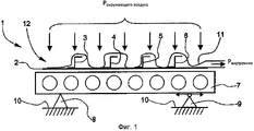
На фиг.1 схематически представлен разрез крупногабаритного конструктивного элемента.Figure 1 schematically shows a section of a large structural element.
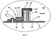
На фиг.2 представлена сложная конструкция в соответствии с известным уровнем техники на примере склеивания стрингера с панелью обшивки в автоклаве.Figure 2 presents a complex structure in accordance with the prior art on the example of gluing a stringer with a panel panel in an autoclave.
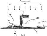
На фиг.3 представлен разрез упрощенной конструкции для осуществления такого же склеивания способом в соответствии с настоящим изобретением.Figure 3 presents a section of a simplified structure for the implementation of the same bonding method in accordance with the present invention.
Одинаковые конструктивные элементы обозначены одинаковыми номерами позиций.Identical structural elements are identified by the same reference numbers.
На фиг.1 представлен разрез конструкции, содержащей несколько элементов, предназначенных для склеивания друг с другом способом в соответствии с настоящим изобретением для изготовления крупногабаритного конструктивного элемента 1.Figure 1 shows a section of a structure containing several elements intended for bonding to each other by the method in accordance with the present invention for the manufacture of large structural element 1.
Крупногабаритный конструктивный элемент 1 может являться, например, посадочным щитком, обшивкой крыла, узлом рулевого управления, узлом руля высоты, частью оболочки фюзеляжа, содержащей, например, несколько отверстий для окон, и т.п. Ниже со ссылками на фиг.1 будет описана последовательность осуществления способа в соответствии с настоящим изобретением.Oversized structural element 1 may be, for example, a landing flap, wing cover, steering assembly, elevator assembly, part of the fuselage shell, containing, for example, several openings for windows, etc. Below with reference to figure 1 will be described the sequence of the method in accordance with the present invention.
Для осуществления способа элементы 2, 3, 4, 5 и 6 помещаются, располагаются и выравниваются друг относительно друга на опорной конструкции 7. Элемент 2 в соответствии с вариантом осуществления настоящего изобретения, представленным на фиг.1, является панелью обшивки, изготовленной из алюминиевого сплава, предназначенной для склеивания с размещенными элементами 3-6 для их армирования. Элементы 3-6, также называемые стрингерами, или армирующими профилями, имеют в основном Z-образную форму поперечного сечения, причем указанные стрингеры служат, помимо прочего, для улучшения механических характеристик панели обшивки. Как и панель обшивки, стрингеры изготовлены из алюминиевого сплава. Вместо используемого алюминиевого сплава элементы 2-6 могут быть изготовлены также из композиционных материалов, например из пластиков, армированных углеродным волокном или других подобных материалов. В качестве альтернативы элементы 2-6 могут также изготавливаться из металлопластикового композиционного материала с покрытием, такого как, например, «Glare».To implement the method, the
Перед осуществлением фактического склеивания необходимые клейкие пленки для изготовления фактического соединения наносятся на необходимые зоны мест соединения между элементами 2-6.Before actual bonding, the necessary adhesive films for making the actual joint are applied to the necessary zones of the joints between the elements 2-6.
Клейкие пленки в виде рулона изготавливаются из материала основы, например нейлоновой ткани, который предварительно пропитывают отверждаемым пластиковым материалом. Для предварительной пропитки материала основы в качестве отверждаемого пластикового материала можно использовать, например, неполностью отвержденные эпоксидные смолы, хранящиеся при низких температурах во избежание преждевременного отверждения. Для осуществления способа в соответствии с настоящим изобретением могут использоваться, например, следующие клейкие пленки: клейкая пленка EA9696.03NW от компании Henkel, Bay Point, США и клейкая пленка FM94M.03 от компании Cytec Engineered Materials, Wrexham, Великобритания. Для большей ясности чертежа клейкие пленки между элементами 2-6 не показаны на фиг.1.The adhesive films in the form of a roll are made of a base material, for example, nylon fabric, which is pre-impregnated with a curable plastic material. For pre-impregnation of the base material as curable plastic material, for example, partially cured epoxy resins stored at low temperatures can be used to prevent premature curing. For implementing the method in accordance with the present invention, for example, the following adhesive films can be used: EA9696.03NW adhesive film from Henkel, Bay Point, USA and FM94M.03 adhesive film from Cytec Engineered Materials, Wrexham, UK. For clarity of the drawing, adhesive films between elements 2-6 are not shown in figure 1.
Перед нанесением склеивающих материалов области мест соединения между элементами 2-6 при необходимости подвергаются соответствующей предварительной обработке, например химической очистке, щелочному и кислотному травлению, анодному оксидированию и нанесению грунтовки и т.п. для усиления адгезионного эффекта и таким образом способности выдерживать механическую нагрузку, достигаемую при клеевом соединении.Before applying the adhesive materials, the areas of the joints between the elements 2-6, if necessary, are subjected to appropriate preliminary processing, for example, chemical cleaning, alkaline and acid etching, anodic oxidation and priming, etc. to enhance the adhesive effect and thus the ability to withstand the mechanical load achieved with adhesive bonding.
Опорная конструкция 7 удерживается на двух опорах 8, 9, и опоры 8, 9 могут неподвижно или с возможностью перемещения соединяться с опорной конструкцией 7. В соответствии с вариантом осуществления настоящего изобретения, представленным на фиг.1, возможность горизонтального перемещения опоры 9 обеспечивает, помимо прочего, компенсацию механических напряжений, которые могут возникать при колебаниях температуры между элементами 2-6 или опорной конструкцией 7. В свою очередь, опоры 8, 9 неподвижно соединены с подложкой 10. Геометрия поверхности опорной конструкции 7 предпочтительно как можно более точно соответствует геометрии поверхности конструктивного элемента 1 для обеспечения высокой точности линейных размеров изготавливаемого крупногабаритного конструктивного элемента 1.The supporting structure 7 is supported on two
Поскольку отверждение клейких пленок, используемых для соединения элементов 2-6, способом в соответствии с настоящим изобретением, осуществляется при температуре 115-125°С и давлении 70-100 кПа, вся конструкция может в отличие от известных способов склеивания, осуществляемых в автоклаве при значительно более высоких давлениях и/или температурах отверждения, покрываться непрерывной вакуумной пленкой 11 без покрывающих средств (клеящих лент, Airweave и т.д.), и без средств увеличения локального контактного давления (силиконовых лент или силиконовых блоков и т.д.) в области склеивания элементов 2-6. Низкие параметры отверждения позволяют отверждать конструкцию, сформированную из элементов 2-6, без использования покрывающих средств и средств обеспечения контактного давления в вакуумном мешке, обеспечивая значительно более простую последовательность изготовления.Since the curing of the adhesive films used to connect the elements 2-6, by the method in accordance with the present invention, is carried out at a temperature of 115-125 ° C and a pressure of 70-100 kPa, the whole structure can, in contrast to the known gluing methods, carried out in an autoclave at significantly higher pressures and / or curing temperatures, coated with a continuous vacuum film 11 without coating agents (adhesive tapes, Airweave, etc.), and without means of increasing local contact pressure (silicone tapes or silicone locks, etc.) in the field of bonding elements 2-6. Low curing parameters allow curing of a structure formed of elements 2-6 without the use of coating means and means of providing contact pressure in a vacuum bag, providing a significantly simpler manufacturing sequence.
Вакуумная пленка 11 вместе с верхней стороной основания 7 образует газонепроницаемый вакуумный мешок 12, который после создания соответствующего частичного вакуума Рвнутреннее и при помощи давления окружающего воздуха Рокружающего воздуха, обеспечивающего достаточное контактное давление между склеиваемыми элементами 2-6, служит для изготовления клеевого соединения, которое может подвергаться высоким механическим нагрузкам. После нанесения вакуумной пленки 11 из созданного таким образом вакуумного мешка 12 частично откачивается воздух, т.е. в нем создается внутреннее давление Рвнутреннее от 70 кПа до 100 кПа, так что давление наружного воздуха Рокружающего воздуха создает контактное давление, необходимое для получения оптимального клеевого соединения между элементами 2-6.The vacuum film 11 together with the upper side of the base 7 forms a gas-
Весь процесс отверждения клейкой пленки 16, в результате которого образуется клеевое соединение, продолжается от 60 до 90 минут при поддержании температуры от 115°С до 125°С.The entire curing process of the
Использование клейкой пленки 16, имеющей более низкие параметры отверждения, обеспечивает указанное отверждение конструкции или всей сборки в вакуумном мешке 12 при относительно низких давлениях от 70 до 100 кПа в указанном интервале температур.The use of an
Отверждение элементов 2-6 способом в соответствии с настоящим изобретением может также осуществляться в автоклаве. Для этого вся конструкция, сформированная из элементов 2-6, вакуумной пленки 11 и опорной конструкции 7, и вся сборка помещаются в автоклав, причем автоклав служит только для обеспечения температуры от 115°С до 125°С, необходимой для удовлетворительного осуществления процесса отверждения, и автоклав уже не подвергается энергоемкому избыточному давлению до 1000 кПа. Вместо этого автоклав для осуществления способа в соответствии с настоящим изобретением не находится под давлением, т.е. работает при давлении окружающего воздуха. Таким образом, любые имеющиеся автоклавы можно продолжать использовать для осуществления способа без использования автоклава в соответствии с настоящим изобретением.The curing of elements 2-6 by the method in accordance with the present invention can also be carried out in an autoclave. For this, the entire structure formed from elements 2-6, the vacuum film 11 and the supporting structure 7, and the entire assembly are placed in an autoclave, and the autoclave serves only to ensure the temperature from 115 ° C to 125 ° C, necessary for satisfactory implementation of the curing process, and the autoclave is no longer subjected to energy-intensive overpressure up to 1000 kPa. Instead, the autoclave for carrying out the method according to the present invention is not pressurized, i.e. works at ambient pressure. Thus, any available autoclaves can continue to be used to carry out the process without using an autoclave in accordance with the present invention.
Однако согласно способу в соответствии с настоящим изобретением отверждение особенно предпочтительно проводить в прямоточной печи непрерывного действия, что обеспечивает непрерывное и, следовательно, более экономичное изготовление крупногабаритных конструктивных элементов для летательного аппарата.However, according to the method in accordance with the present invention, curing is particularly preferably carried out in a continuous-flow furnace, which provides continuous and, therefore, more economical manufacture of large-sized structural elements for an aircraft.
По завершении процесса отверждения вакуумная пленка 11, которая не может использоваться повторно, может быть снята со склеенных элементов 2-6, и крупногабаритный конструктивный элемент 1 можно подвергать заключительной обработке. Однако затраты на заключительную обработку конструктивного элемента 1 значительно снижены, благодаря применению способа без использования автоклава в соответствии с настоящим изобретением, поскольку, как уже говорилось, отсутствует необходимость в дополнительных покрывающих средствах, таких как, например, покрывающие ленты и т.п., в частности в острокромочных зонах и на фиксирующих штырях, или средствах увеличения локального контактного давления, и, следовательно, необходимость их удаления.Upon completion of the curing process, the vacuum film 11, which cannot be reused, can be removed from the glued elements 2-6, and the large-sized structural element 1 can be subjected to final processing. However, the cost of the final processing of the structural element 1 is significantly reduced due to the use of the method without the use of an autoclave in accordance with the present invention, since, as already mentioned, there is no need for additional coating means, such as, for example, covering tapes and the like, in particular in sharp-edged zones and on fixing pins, or means of increasing local contact pressure, and, therefore, the need to remove them.
Кроме того, при применении способа в соответствии с настоящим изобретением значительно снижается необходимость в дополнительной очистке склеенных элементов 2-6, поскольку благодаря вакуумному отверждению между склеиваемыми элементами 2-6, требуется уменьшенное контактное давление, что в основном исключает нежелательное появление клея (выдавливание) между склеиваемыми элементами 2-6. Трудоемкая заключительная обработка элементов 2-6, ранее обычно необходимая после отверждения клейкой пленки 16, например, очистка агрессивными холодными очистителями, химическими огрубляющими средствами, шлифовальными составами и/или полирующими присадками и т.д., может быть также в основном исключена без замены.In addition, when applying the method in accordance with the present invention, the need for additional cleaning of the glued elements 2-6 is significantly reduced, since due to vacuum curing between the glued elements 2-6, a reduced contact pressure is required, which basically eliminates the undesirable appearance of glue (extrusion) between glued elements 2-6. The time-consuming final processing of elements 2-6, previously usually necessary after curing the
Поскольку склеиваемые элементы 2-6 отверждаются без использования автоклава, т.е. в основном только в вакуумном мешке 12 при относительно низких контактных давлениях, опорную конструкцию 7 более просто выполнить в статическом режиме. Нет необходимости использовать опорную конструкцию 7, изготовленную, например, из стали, которая является относительно прочной, дорогостоящей и сложной в изготовлении.Since the bonding elements 2-6 cure without the use of an autoclave, i.e. mainly only in the
На фиг.2 представлена известная сложная конструкция, используемая для склеивания стрингера 13 с панелью обшивки 14 в автоклаве.Figure 2 presents the well-known complex structure used for bonding the
Клейкая пленка 16, формирующая фактическое механическое соединение между обшивкой 14 и стрингером 13, размещается между обшивкой 14 и стрингером 13 в области мест 15 соединения. Фиксирующий штырь 17 используется для первоначальной фиксации положения стрингера 13 относительно обшивки 14 до завершения процесса отверждения. По завершении процесса отверждения фиксирующий штырь 17 может быть удален. Во избежание прокалывания вакуумной пленки 18 из-за высоких избыточных давлений, действующих на изделие в автоклаве 19, фиксирующий штырь 17 покрывается клеящей пленкой 20. Первый силиконовый блок 22 устанавливается в качестве прижимного элемента в зоне нижней части 21 стрингера 13 для увеличения локального контактного давления в этой зоне. Второй силиконовый блок 23 располагается в качестве прижимного элемента между верхней частью 24 стрингера 13 и панелью обшивки 14 для предотвращения отклонения стрингера 13 при приложении давления. Во избежание загрязнения зоны места 15 соединения обшивки 14 налетом силикона от силиконовых блоков 22, 23 первый силиконовый блок 22 окружается снимаемой пленкой 25. Соответственно второй силиконовый блок 23 при необходимости также должен быть обернут такой снимаемой пленкой. Верхняя часть 24 стрингера 13 и центральная стенка 26 стрингера 13 покрываются клеящей лентой 27 для изготовления конструкции или всей сборки, помещаемой в автоклав. Покрытие острокромочных зон стрингера 13 и фиксирующего штифта 17 клеящими лентами 20, 27 предотвращает повреждение вакуумной пленки 18 от прокалывания или прорыва из-за высокого избыточного давления до 1000 кПа, преобладающего в автоклаве 19. Затем вся конструкция или вся сборка помещается в автоклав 19 и клейкая пленка 16 отверждается при температуре 125-130°С и при давлении до 1000 кПа в течение нескольких часов для окончательного соединения стрингера 13 с обшивкой 14.An
На фиг.3 представлена упрощенная конструкция, содержащая все необходимое для осуществления способа в соответствии с настоящим изобретением.Figure 3 presents a simplified design containing everything necessary for the implementation of the method in accordance with the present invention.
Стрингер 13 размещается на обшивке 14, как показано на фиг.2. Клейкая пленка 16 размещается между стрингером 13 и обшивкой 14 в области мест 15 соединения. Фиксирующий штифт 17 для первоначальной фиксации положения стрингера 13 на обшивке 14 уже не должен покрываться ранее необходимой клеящейся лентой 20. То же относится к первому и второму силиконовым блокам 22, 23, включая покрытие силиконовых блоков 22, 23 снимаемой пленкой 25. Кроме того, исключается клеящая лента 27 для покрытия верхних, острокромочных зон стрингера 13.
При использовании способа в соответствии с настоящим изобретением необходимо снабдить обшивку 14 и стрингер 13 в зоне места 15 соединения только вакуумной пленкой 18, так что издержки, связанные с изготовлением или подгонкой конструкции, состоящей из стрингера 13, панели обшивки 14, клейкой пленки 16 и вакуумной пленки 18, значительно снижаются.When using the method in accordance with the present invention, it is necessary to provide the
В соответствии с изготовлением конструкции по фиг.3 из вакуумного мешка 28, образованного вакуумной пленкой 18, частично откачивается воздух, так что в вакуумном мешке 28 устанавливается внутреннее давление Рвнутреннее приблизительно 70-100 кПа для создания необходимого механического контактного давления между стрингером 24 и обшивкой 14 под действием давления окружающего воздуха Рокружающего воздуха.In accordance with the construction of FIG. 3, air is partially pumped out of the
Конструкция, сформированная таким образом, помещается затем для окончательного отверждения в автоклав для обеспечения необходимой температуры отверждения 115-125°С при давлении 70-100 кПа в течение периода отверждения 60-90 минут. Автоклав служит здесь только для поддержания необходимой температуры отверждения в диапазоне между 115°С и 125°С, и в соответствии с настоящим изобретением уже не требуется создания избыточного давления до 1000 кПа.The structure thus formed is then placed for final curing in an autoclave to provide the necessary curing temperature of 115-125 ° C at a pressure of 70-100 kPa for a curing period of 60-90 minutes. The autoclave here serves only to maintain the necessary curing temperature in the range between 115 ° C and 125 ° C, and in accordance with the present invention no longer requires the creation of excess pressure up to 1000 kPa.
В качестве альтернативы, для обеспечения непрерывного и, следовательно, более экономичного процесса изготовления изображенную конструкцию можно подвергать отверждению, если способ в соответствии с настоящим изобретением преимущественно применяют в прямоточной печи без приложения давления.Alternatively, in order to ensure a continuous and therefore more economical manufacturing process, the depicted construction can be cured if the method according to the present invention is advantageously used in a direct-flow furnace without applying pressure.
Перечень позиций:The list of positions:
1 - конструктивный элемент1 - structural element
2 - элемент (обшивка)2 - element (sheathing)
3 - элемент (стрингер)3 - element (stringer)
4 - элемент (стрингер)4 - element (stringer)
5 - элемент (стрингер)5 - element (stringer)
6 - элемент (стрингер)6 - element (stringer)
7 - опорная конструкция7 - supporting structure
8 - опора8 - support
9 - опора9 - support
10 - подложка10 - substrate
11 - вакуумная пленка11 - vacuum film
12 - вакуумный мешок12 - vacuum bag
13 - стрингер13 - stringer
14 - панель обшивки14 - panel skin
15 - места соединения15 - connection points
16 - клейкая пленка16 - adhesive film
17 - фиксирующий штырь17 - fixing pin
18 - вакуумная пленка18 - vacuum film
19 - автоклав19 - autoclave
20 - клеящая лента20 - adhesive tape
21 - нижняя часть стрингера21 - lower part of the stringer
22 - первый силиконовый блок22 - the first silicone block
23 - второй силиконовый блок23 - second silicone block
24 - верхняя часть стрингера24 - the upper part of the stringer
25 - снимаемая пленка25 - removable film
26 - центральная стенка стрингера26 - the central wall of the stringer
27 - клеящая лента27 - adhesive tape
28 - вакуумный мешок28 - vacuum bag
Claims (4)
Applications Claiming Priority (2)
| Application Number | Priority Date | Filing Date | Title |
|---|---|---|---|
| DE102006007429A DE102006007429B4 (en) | 2006-02-17 | 2006-02-17 | Method for autoclave-free bonding of components for aircraft |
| DE102006007429.7 | 2006-02-17 |
Publications (2)
| Publication Number | Publication Date |
|---|---|
| RU2008132424A RU2008132424A (en) | 2010-03-27 |
| RU2425778C2 true RU2425778C2 (en) | 2011-08-10 |
Family
ID=38016864
Family Applications (1)
| Application Number | Title | Priority Date | Filing Date |
|---|---|---|---|
| RU2008132424/11A RU2425778C2 (en) | 2006-02-17 | 2007-02-16 | Method to glue elements for aircraft without application of autoclave |
Country Status (10)
| Country | Link |
|---|---|
| US (1) | US20100012268A1 (en) |
| EP (1) | EP1984241B1 (en) |
| JP (1) | JP2009526697A (en) |
| CN (1) | CN101384478A (en) |
| AT (1) | ATE469024T1 (en) |
| BR (1) | BRPI0707947A2 (en) |
| CA (1) | CA2640314A1 (en) |
| DE (2) | DE102006007429B4 (en) |
| RU (1) | RU2425778C2 (en) |
| WO (1) | WO2007093636A1 (en) |
Families Citing this family (27)
| Publication number | Priority date | Publication date | Assignee | Title |
|---|---|---|---|---|
| DE102006013069B3 (en) * | 2006-03-22 | 2007-12-06 | Airbus Deutschland Gmbh | bolt connection |
| DE102008029058A1 (en) * | 2008-06-18 | 2009-12-24 | GKN Aerospace Services Limited, East Cowes | Method and mold for making fiber reinforced composite components with microwaves |
| CN101791761A (en) * | 2010-04-07 | 2010-08-04 | 中国航空工业集团公司北京航空制造工程研究所 | Method for compensating for matching surface gap of skeleton and skin of aircraft structure |
| CN101913250A (en) * | 2010-08-17 | 2010-12-15 | 沈阳飞机工业(集团)有限公司 | Rudder wall plate molding process |
| US9028643B2 (en) * | 2010-08-30 | 2015-05-12 | Corning Incorporated | Methods of bonding and articles formed thereby |
| JP5698526B2 (en) | 2010-12-27 | 2015-04-08 | 川崎重工業株式会社 | Mold |
| WO2012090468A1 (en) | 2010-12-27 | 2012-07-05 | 川崎重工業株式会社 | Molding die, molding jig, and molding method |
| RU2618055C2 (en) * | 2012-11-26 | 2017-05-02 | Сайтек Индастриз Инк. | Composite materials bonding |
| US9555578B2 (en) | 2012-11-30 | 2017-01-31 | The Boeing Company | Transfer system and method for applying a film material to an elongate member |
| US9676160B2 (en) | 2012-11-30 | 2017-06-13 | The Boeing Company | Holding system for elongate members |
| US9067374B2 (en) | 2012-11-30 | 2015-06-30 | The Boeing Company | Method and apparatus for applying film material to elongate members |
| CN103213285B (en) * | 2013-04-24 | 2015-08-05 | 哈尔滨飞机工业集团有限责任公司 | A kind of forming method of variable cross-section enclosed cavity composite material element |
| US11052619B1 (en) | 2013-04-29 | 2021-07-06 | Plastics Unlimited, Inc. | Fabrication apparatuses and methods |
| US11969931B1 (en) * | 2013-04-29 | 2024-04-30 | Plastics Unlimited, Inc. | Fabrication apparatuses and methods |
| US10807320B1 (en) | 2013-04-29 | 2020-10-20 | Terry Kieffer | Fabrication apparatuses and methods |
| US9403350B2 (en) * | 2013-12-16 | 2016-08-02 | The Nordam Group, Inc. | Flash control metal bonding |
| US9518907B2 (en) * | 2014-01-16 | 2016-12-13 | The Boeing Company | Methods and apparatus to determine integrity of composite structures |
| CN105538745A (en) * | 2015-12-14 | 2016-05-04 | 中国商用飞机有限责任公司 | Forming method of aluminum alloy fiber laminate structural part and laminate structural part thereof |
| DE102016106830B3 (en) * | 2016-04-13 | 2017-09-14 | Airbus Operations Gmbh | A support for covering a curable fiber composite material layer, system assembly having such a support, and methods using such a support |
| NL2017062B1 (en) * | 2016-06-28 | 2018-01-05 | Fokker Aerostructures Bv | Method for manufacturing a panel with thickening |
| EP3287271B1 (en) * | 2016-08-26 | 2020-11-18 | Airbus Defence and Space GmbH | Film for forming an air flow surface on a body, outer casing part for a vehicle and method for forming an air flow surface on a body |
| GB201704890D0 (en) * | 2017-03-28 | 2017-05-10 | Composite Tech And Applications Ltd | A tool for manufacturing a composite component |
| US10766212B2 (en) * | 2017-12-13 | 2020-09-08 | The Boeing Company | Method and apparatus for forming radius filler kits |
| DE102018125979A1 (en) * | 2018-10-19 | 2020-04-23 | Airbus Operations Gmbh | Method and system for connecting two components |
| CN109436374B (en) * | 2018-11-30 | 2022-04-01 | 中国航空工业集团公司沈阳飞机设计研究所 | Installation method of cockpit cover in airplane fatigue test |
| US12134258B2 (en) | 2019-06-19 | 2024-11-05 | Safran Aircraft Engines | Adhesive assembly method and an adhesive assembly obtained by the method |
| CN115234555A (en) * | 2022-06-23 | 2022-10-25 | 上海宇航系统工程研究所 | A preparation method for bonding cork on the surface of a large-diameter riveted cabin body |
Citations (4)
| Publication number | Priority date | Publication date | Assignee | Title |
|---|---|---|---|---|
| US5242523A (en) * | 1992-05-14 | 1993-09-07 | The Boeing Company | Caul and method for bonding and curing intricate composite structures |
| SU1744893A1 (en) * | 1989-03-21 | 1996-04-10 | Таганрогское авиационное производственное объединение | Method of assembly of flying vehicle wing |
| RU2137679C1 (en) * | 1997-09-01 | 1999-09-20 | Государственно-акционерное общество "Ташкентское авиационное производственное объединение им.В.П.Чкалова" | Method of assembly of wing of flying vehicle |
| WO2001096094A2 (en) * | 2000-06-15 | 2001-12-20 | Alliant Techsystems Inc. | Conformable locating aperture system and method for alignment of members |
Family Cites Families (15)
| Publication number | Priority date | Publication date | Assignee | Title |
|---|---|---|---|---|
| US3678130A (en) * | 1970-09-10 | 1972-07-18 | Dexter Corp | Adhesive compositions containing epoxy resin, carboxy containing copolymer and 1,5-dihydrozynaphthalene |
| US4560428A (en) * | 1984-08-20 | 1985-12-24 | Rockwell International Corporation | System and method for producing cured composites |
| US4966802A (en) * | 1985-05-10 | 1990-10-30 | The Boeing Company | Composites made of fiber reinforced resin elements joined by adhesive |
| US4983672A (en) * | 1987-12-23 | 1991-01-08 | Minnesota Mining And Manufacturing Company | Epoxide resin compositions and method |
| US5618606A (en) * | 1989-09-18 | 1997-04-08 | Rockwell International Corporation | Process for bonding staged composites with a cobonded staged adhesive and article |
| JPH0814082B2 (en) * | 1990-08-27 | 1996-02-14 | 財団法人鉄道総合技術研究所 | Method of forming nose rail for crossing and method of forming crossing |
| US6849150B1 (en) * | 2001-01-16 | 2005-02-01 | Lockheed Martin Corporation | System and method of forming structural assemblies with 3-D woven joint pre-forms |
| EP1401658A4 (en) * | 2001-04-06 | 2008-01-23 | Gen Dynamics Armament & Tech | Method of manufacturing a hollow section, grid stiffened panel |
| JP4856327B2 (en) * | 2001-07-03 | 2012-01-18 | 富士重工業株式会社 | Method for manufacturing composite panel |
| US20030019567A1 (en) * | 2001-07-26 | 2003-01-30 | Burpo Steven J. | Vacuum assisted resin transfer method for co-bonding composite laminate structures |
| EP1336469A1 (en) * | 2002-02-19 | 2003-08-20 | Alenia Aeronautica S.P.A. | Methods of manufacturing a stiffening element for an aircraft skin panel and a skin panel provided with the stiffening element |
| NO316296B1 (en) * | 2002-04-05 | 2004-01-05 | Hiform As | Lightweight ballistic protection and method of manufacturing such |
| DE10320791B4 (en) * | 2002-11-06 | 2016-09-15 | Airbus Operations Gmbh | Process for producing textile preforms from textile semi-finished products |
| JP2005022171A (en) * | 2003-06-30 | 2005-01-27 | Mitsubishi Heavy Ind Ltd | Core for composite material sandwich panel, composite material sandwich panel and its manufacturing method |
| US20050126699A1 (en) * | 2003-12-15 | 2005-06-16 | Anna Yen | Process for the manufacture of composite structures |
-
2006
- 2006-02-17 DE DE102006007429A patent/DE102006007429B4/en not_active Expired - Fee Related
-
2007
- 2007-02-16 EP EP07726400A patent/EP1984241B1/en not_active Not-in-force
- 2007-02-16 BR BRPI0707947-8A patent/BRPI0707947A2/en not_active IP Right Cessation
- 2007-02-16 JP JP2008554783A patent/JP2009526697A/en active Pending
- 2007-02-16 CA CA002640314A patent/CA2640314A1/en not_active Abandoned
- 2007-02-16 US US12/223,577 patent/US20100012268A1/en not_active Abandoned
- 2007-02-16 DE DE602007006764T patent/DE602007006764D1/en active Active
- 2007-02-16 RU RU2008132424/11A patent/RU2425778C2/en not_active IP Right Cessation
- 2007-02-16 AT AT07726400T patent/ATE469024T1/en not_active IP Right Cessation
- 2007-02-16 CN CNA2007800058208A patent/CN101384478A/en active Pending
- 2007-02-16 WO PCT/EP2007/051511 patent/WO2007093636A1/en not_active Ceased
Patent Citations (4)
| Publication number | Priority date | Publication date | Assignee | Title |
|---|---|---|---|---|
| SU1744893A1 (en) * | 1989-03-21 | 1996-04-10 | Таганрогское авиационное производственное объединение | Method of assembly of flying vehicle wing |
| US5242523A (en) * | 1992-05-14 | 1993-09-07 | The Boeing Company | Caul and method for bonding and curing intricate composite structures |
| RU2137679C1 (en) * | 1997-09-01 | 1999-09-20 | Государственно-акционерное общество "Ташкентское авиационное производственное объединение им.В.П.Чкалова" | Method of assembly of wing of flying vehicle |
| WO2001096094A2 (en) * | 2000-06-15 | 2001-12-20 | Alliant Techsystems Inc. | Conformable locating aperture system and method for alignment of members |
Also Published As
| Publication number | Publication date |
|---|---|
| RU2008132424A (en) | 2010-03-27 |
| JP2009526697A (en) | 2009-07-23 |
| CN101384478A (en) | 2009-03-11 |
| DE102006007429A1 (en) | 2007-08-30 |
| ATE469024T1 (en) | 2010-06-15 |
| US20100012268A1 (en) | 2010-01-21 |
| EP1984241B1 (en) | 2010-05-26 |
| WO2007093636A1 (en) | 2007-08-23 |
| BRPI0707947A2 (en) | 2011-05-17 |
| DE602007006764D1 (en) | 2010-07-08 |
| CA2640314A1 (en) | 2007-08-23 |
| DE102006007429B4 (en) | 2011-08-18 |
| EP1984241A1 (en) | 2008-10-29 |
Similar Documents
| Publication | Publication Date | Title |
|---|---|---|
| EP1984241B1 (en) | Method for autoclave-free adhesive bonding of components for aircraft | |
| EP1268120B1 (en) | Method of joining composite components | |
| US11235494B2 (en) | Method of manufacturing composite material structure | |
| US11230034B2 (en) | Method and apparatus for producing an aircraft structural component | |
| US8636865B2 (en) | Method of making a composite fibre component with thermoplastic stiffening elements | |
| JP2003072691A (en) | Method of manufacturing composite wing and composite wing | |
| US9649820B1 (en) | Assembly using skeleton structure | |
| US9051062B1 (en) | Assembly using skeleton structure | |
| US20080083494A1 (en) | Method for joining precured or cured stringers to at least one structural component of an aircraft or spacecraft | |
| US10974471B2 (en) | Mold for manufacturing composite material structure | |
| CA2883051C (en) | An apparatus and method for stiffeners | |
| US20140186574A1 (en) | Method for producing and connecting fibre-reinforced components and aircraft or spacecraft | |
| CN101203374B (en) | process used to produce roughly shell-shaped components | |
| US8574391B2 (en) | Method for joining a profiled first structural component to a second structural component | |
| US20240400226A1 (en) | Method For Joining A Window Frame To A Fuselage Skin Of An Aircraft Made Of A Fiber Composite Material | |
| AU2001237133B2 (en) | Production, forming, bonding, joining and repair systems for composite and metal components |
Legal Events
| Date | Code | Title | Description |
|---|---|---|---|
| PD4A | Correction of name of patent owner | ||
| MM4A | The patent is invalid due to non-payment of fees |
Effective date: 20180217 |